
16-Bit
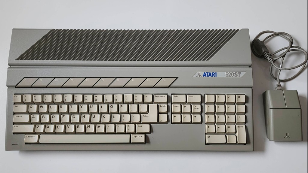
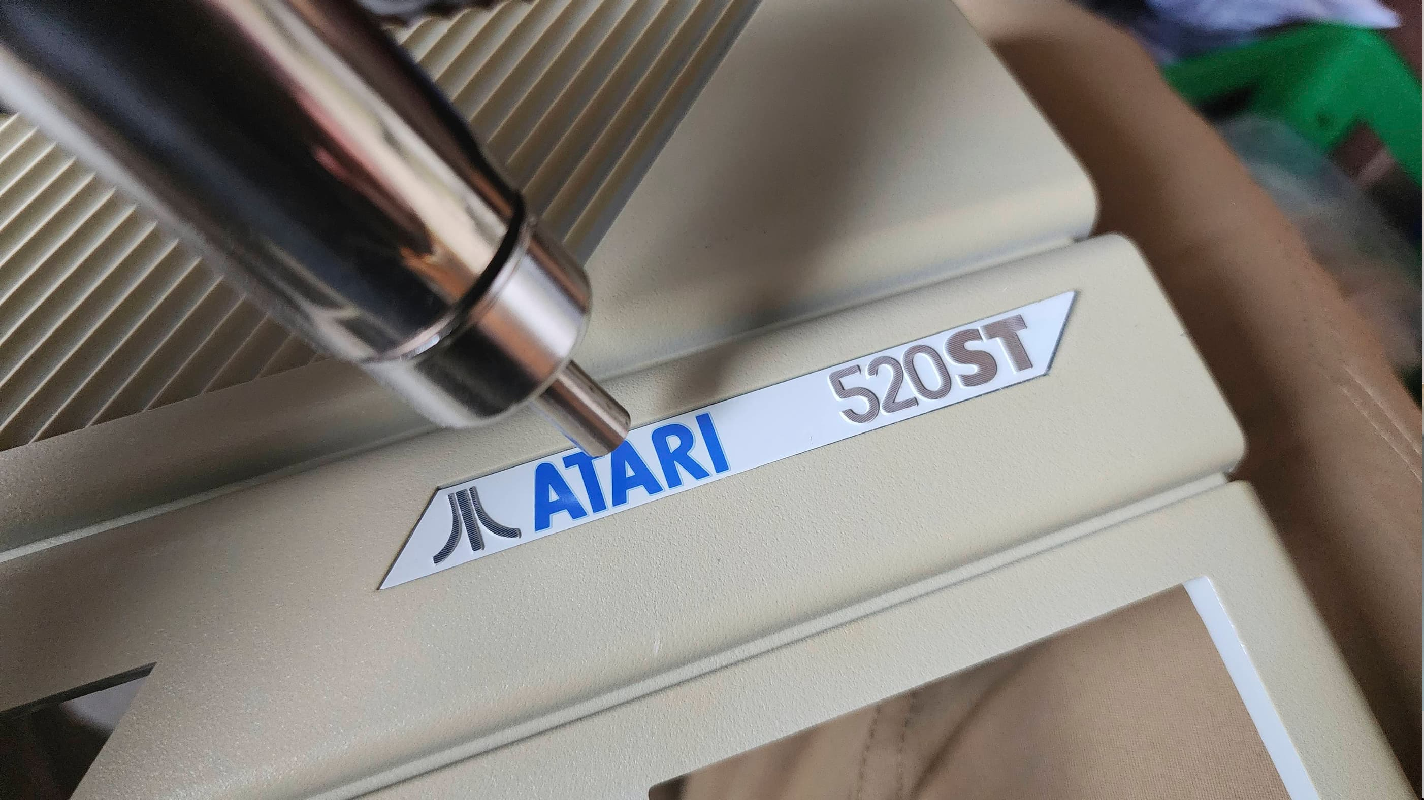
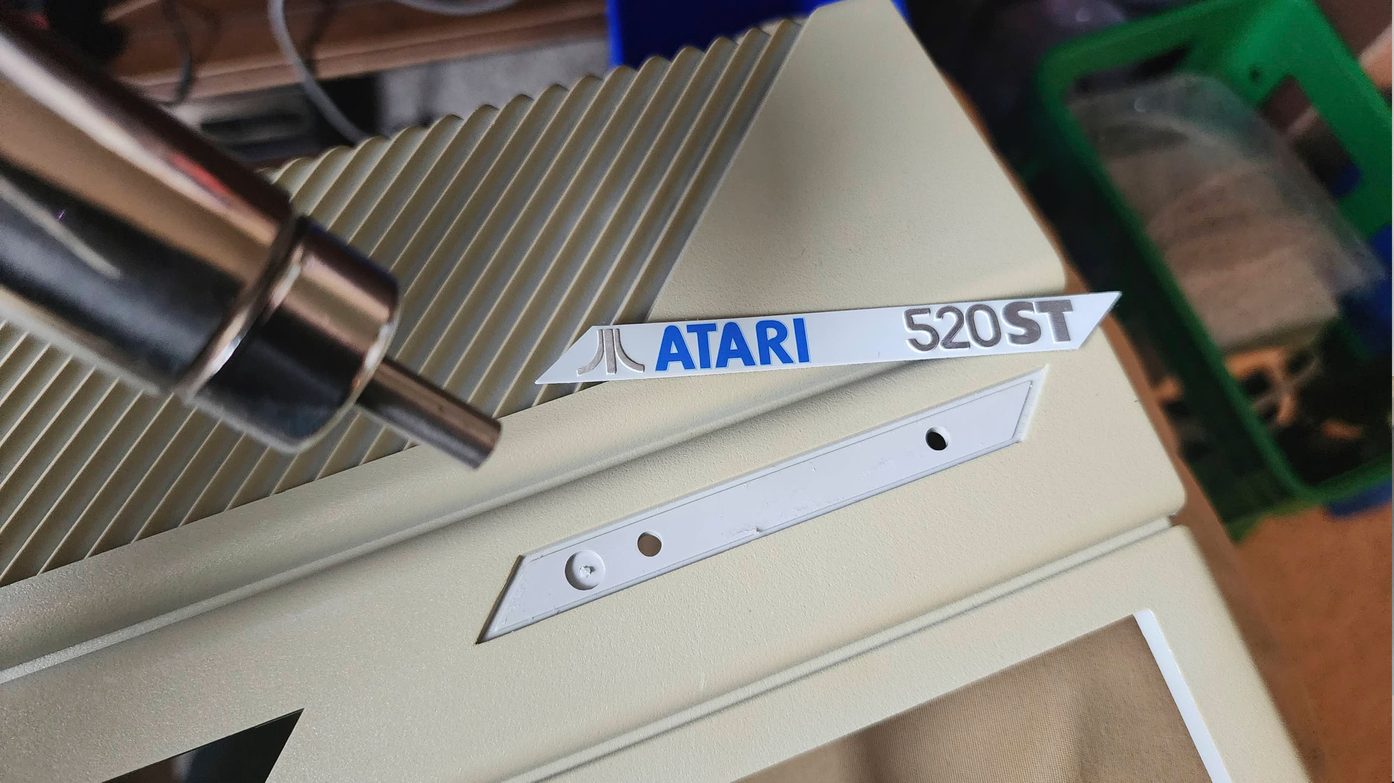
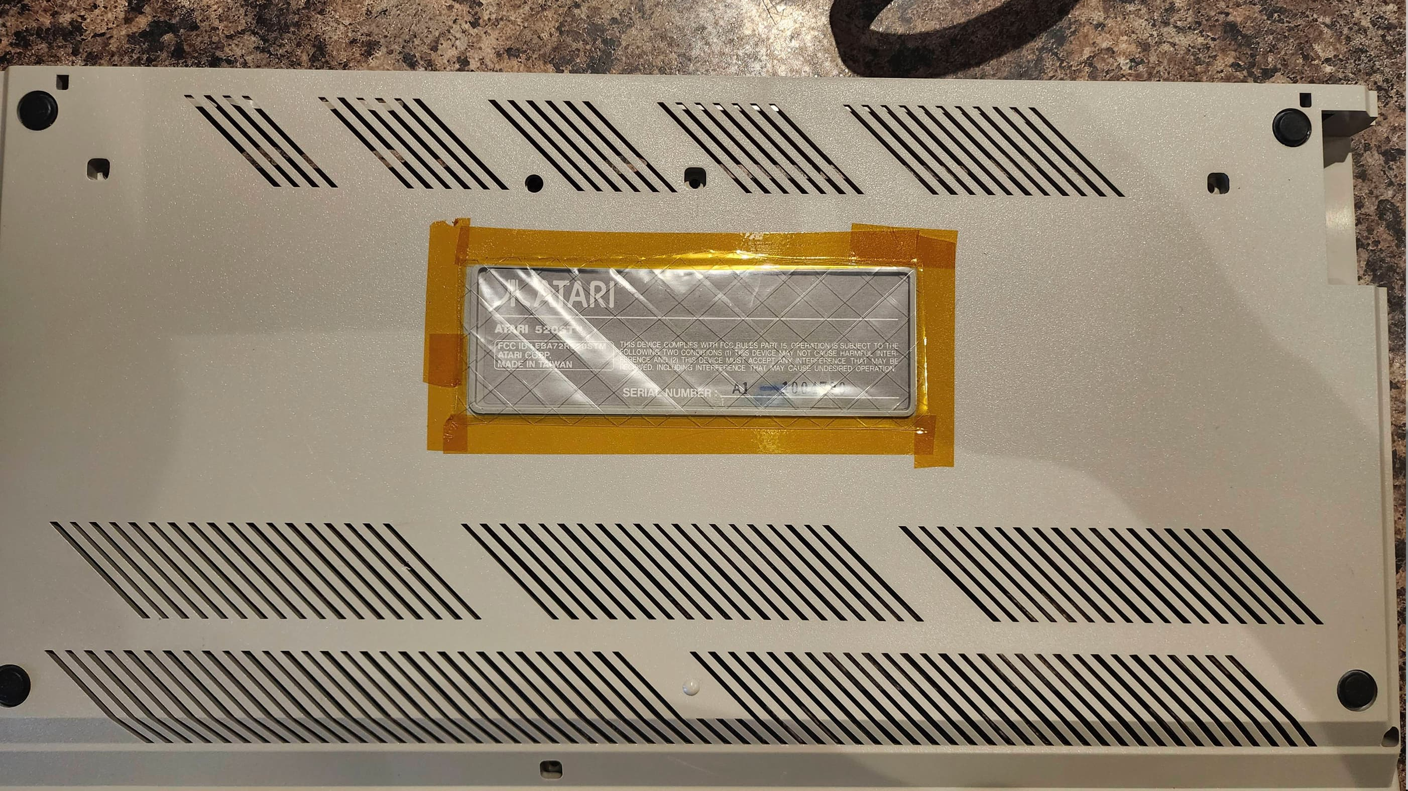
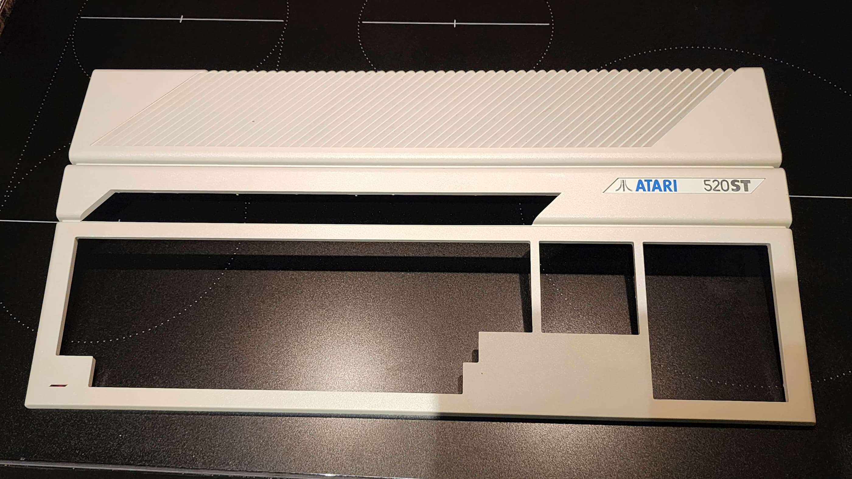
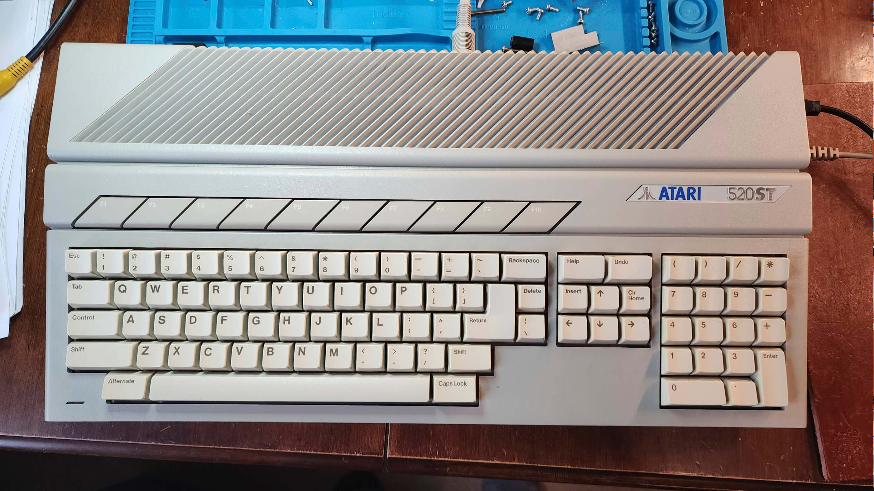
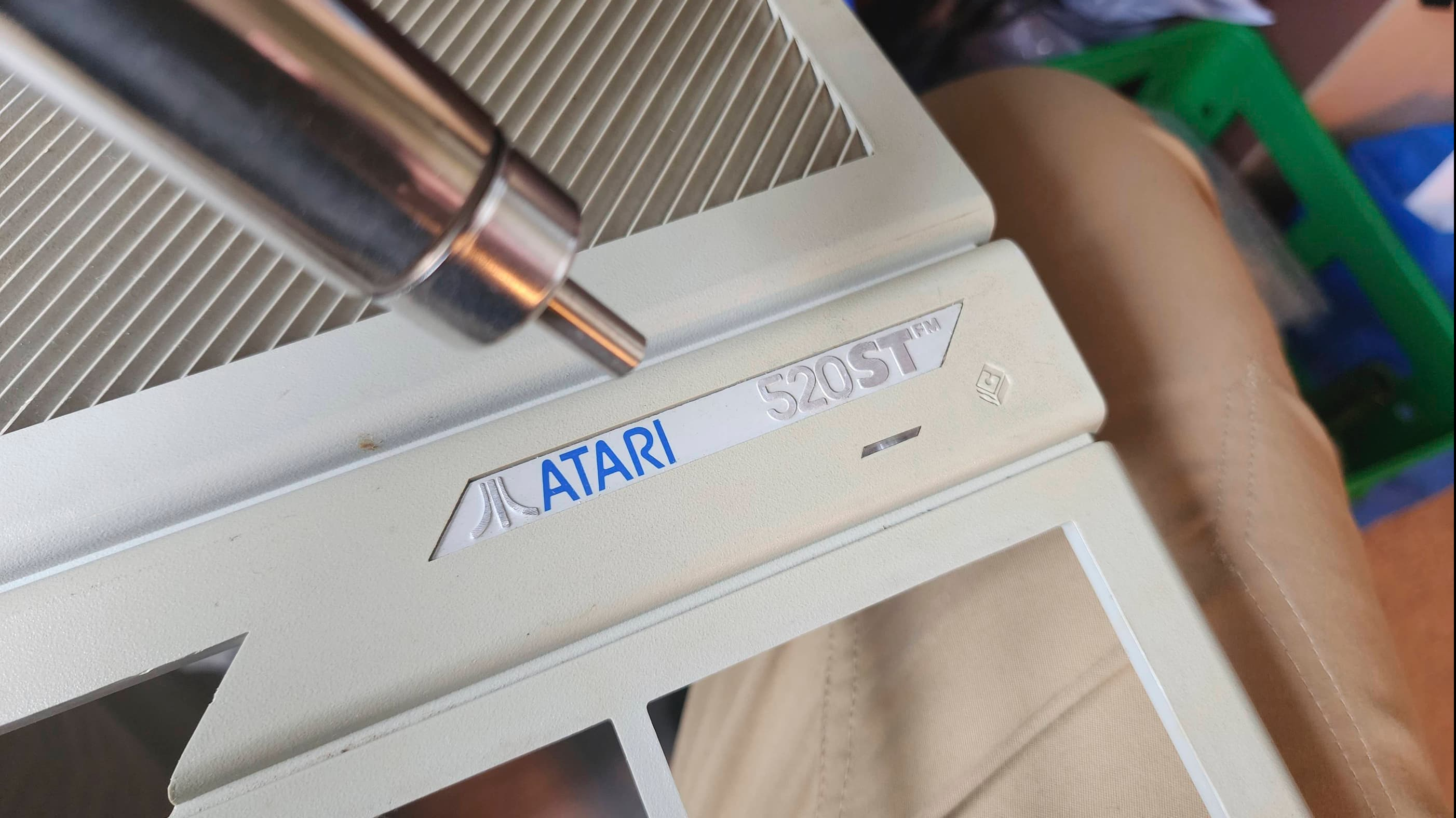
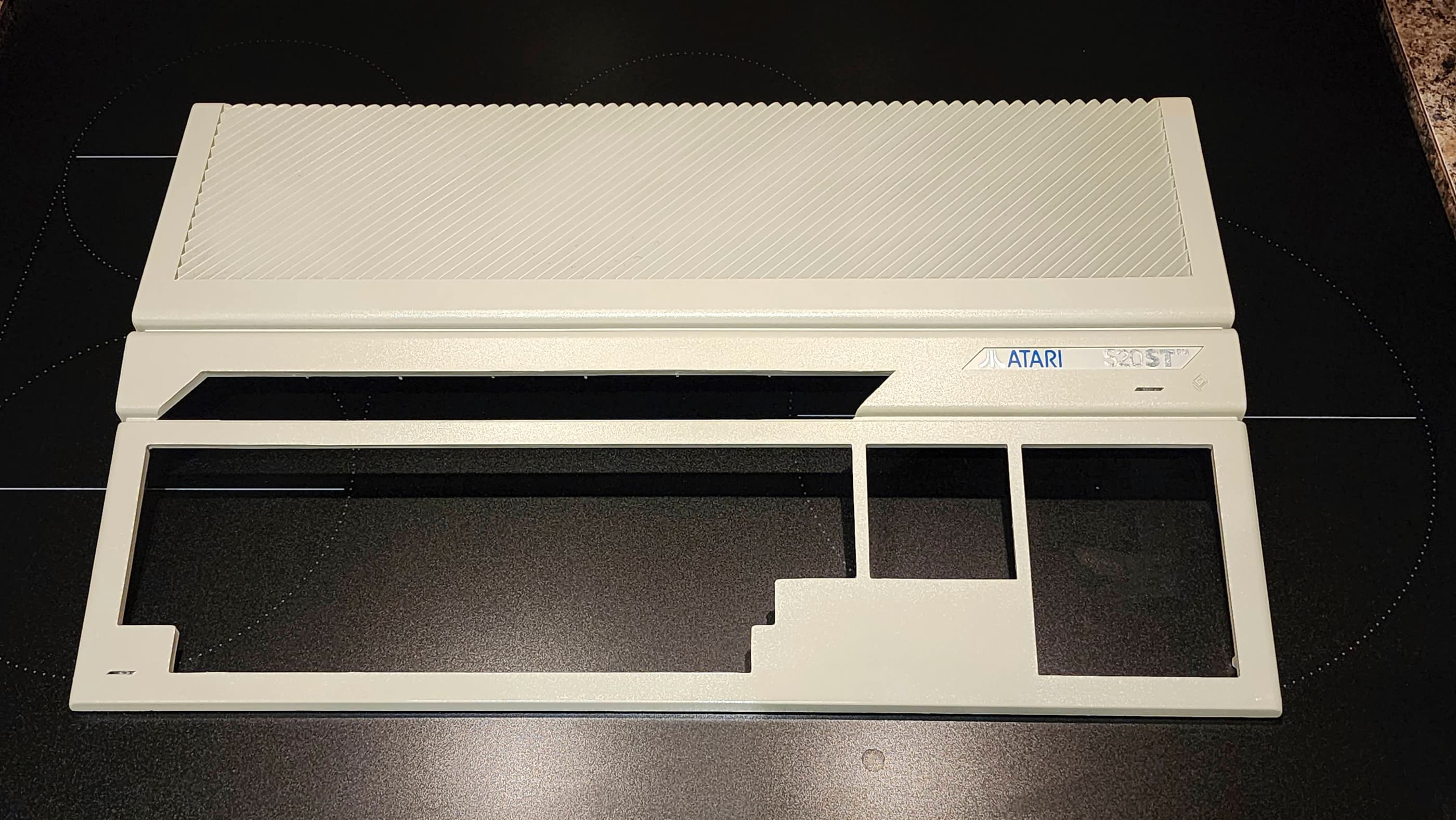
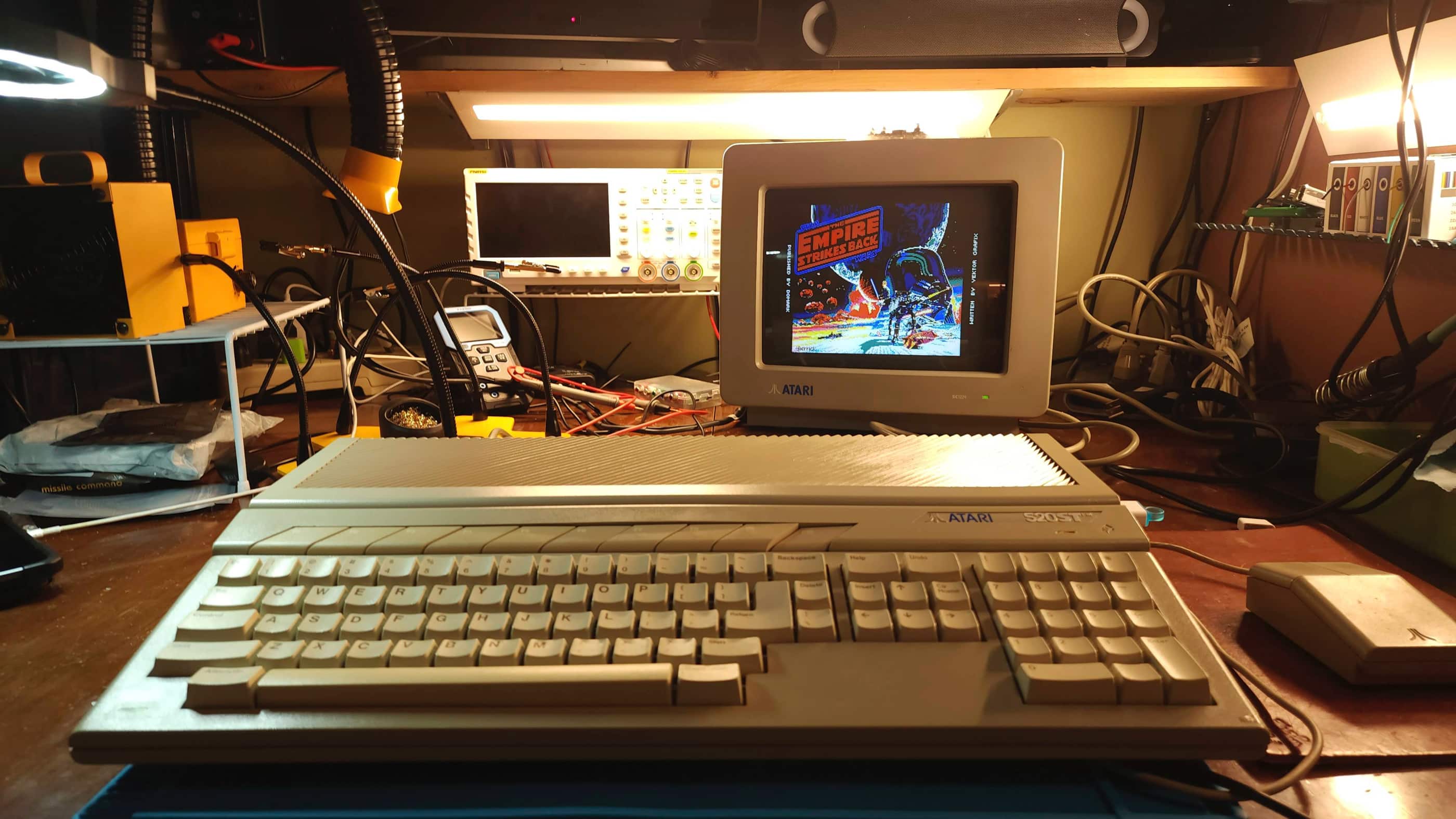
Atari 520STM
Years (1985-1993)
Interesting Fact: The Atari ST was the offspring of Jack Tramiel’s abrupt departure from Commodore in 1983 and his subsequent purchase of Atari in 1984. Along with Jack and his sons, a number of Commodore engineers and programmers jumped ship and joined Tramiel at Atari. One of these engineers was, Shiraz Shivij, who had helped develop the Commodore 64. It was while at Atari, that Shivij and Tramiel had begun to develop a new 16-bit machine for Commodore. (source) Concurrently, Jay Miner had approached Atari about a licensing deal that would allow Atari to sell the upcoming Amiga computer that was still in development. (source) When Tramiel took over Atari, Commodore stepped in and paid off Miner’s debt to Atari and as Peter Leigh notes, “this all led to the rather back-to-front situation of Commodore owning Atari’s old investment – The Amiga, and Atari starting development of what would have been Commodore’s 16 bit machine, under Jack Tramiel’s team.” (source)
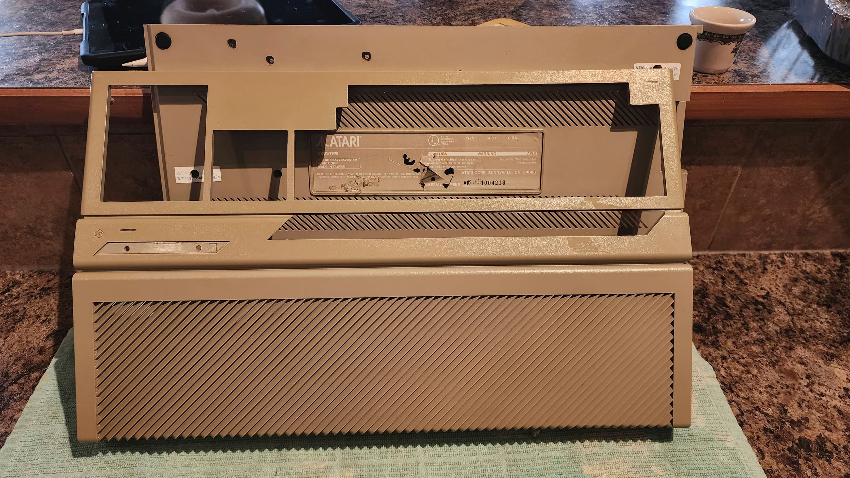
Released two months prior to the Amiga 1000, the 520 ST derived its name from 512 KBs of memory and its sixteen-bit external data bus and its thirty-two-bit internal data bus, hence, ST for sixteen / thirty-two. (source) Using the same Motorola 68000 processor as the Amiga, the ST was the first mass produced computer to use a coloured graphics user interface (GUI) with its GEM desktop and TOS OS. (source) It also became the ‘go to’ computer for use in the recording industry due to its inclusion of two MIDI ports; though its Yamaha sound chip was not even close to the caliber of the Amiga’s. (source) The 520 STM was the second model of the ST that was released with the ‘M’ indicating the inclusion of an RF modulator for television output. It also included six ROM chips that allowed TOS 1.0 to not have to boot from floppy as with the original 520 ST. (source) However, like the original, the STM did not include an internal floppy drive.
To see an interesting video on the history of the Atari ST, I’d recommend Peter Leigh’s (aka Nostalgia Nerd), ‘The Atari ST Story’.
Condition When Acquired: Non-Functional
Current Condition: Fully Functional


Project Details: Being an Amiga guy growing up, I’d heard about the ST, but always assumed the pre-eminence of the Amiga. However, after fixing up two Amiga 500s and an Amiga 1200, I was really curious to see how the ST compared. So curious in fact, that I somehow ended up with a 520 STM, a 520 STFM, and a 1040STFM along with an Atari SC1435 monitor and an Atari SC1224 monitor.
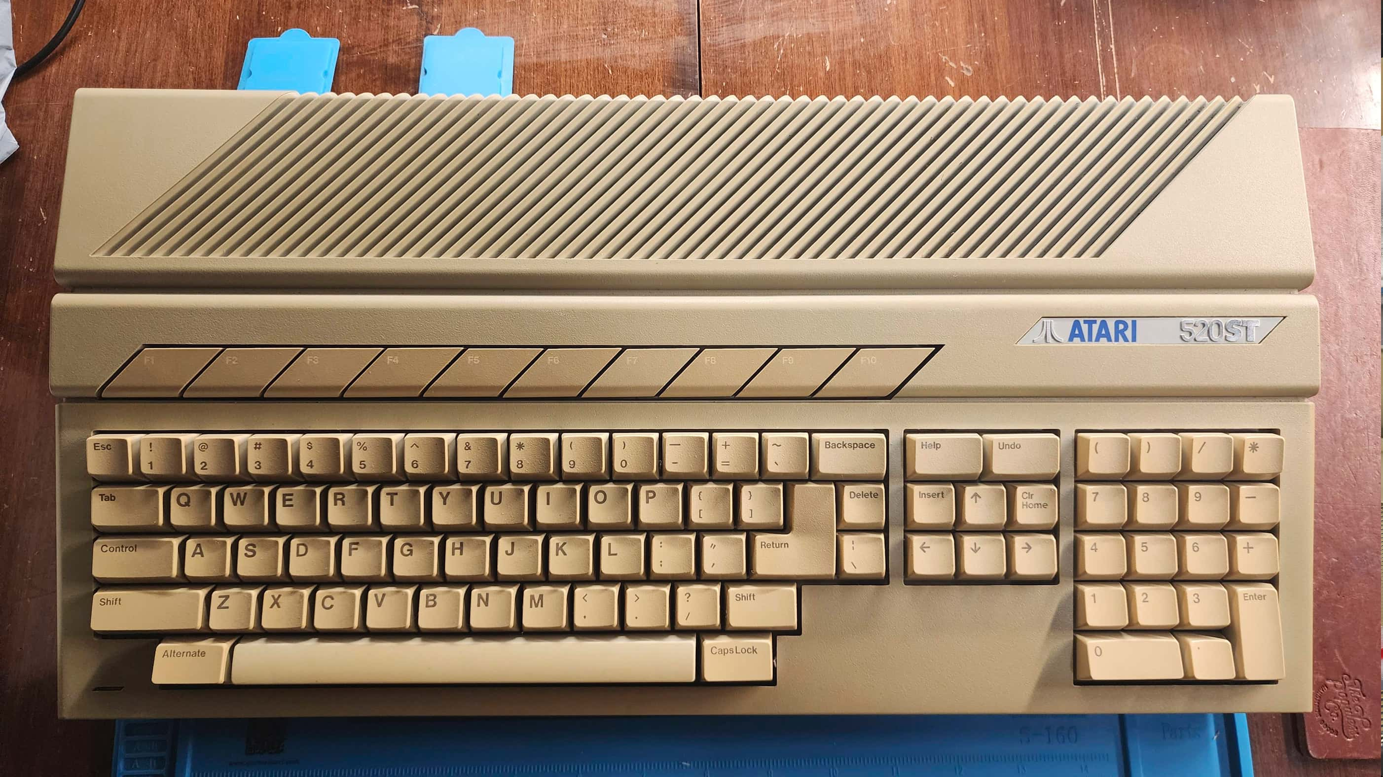
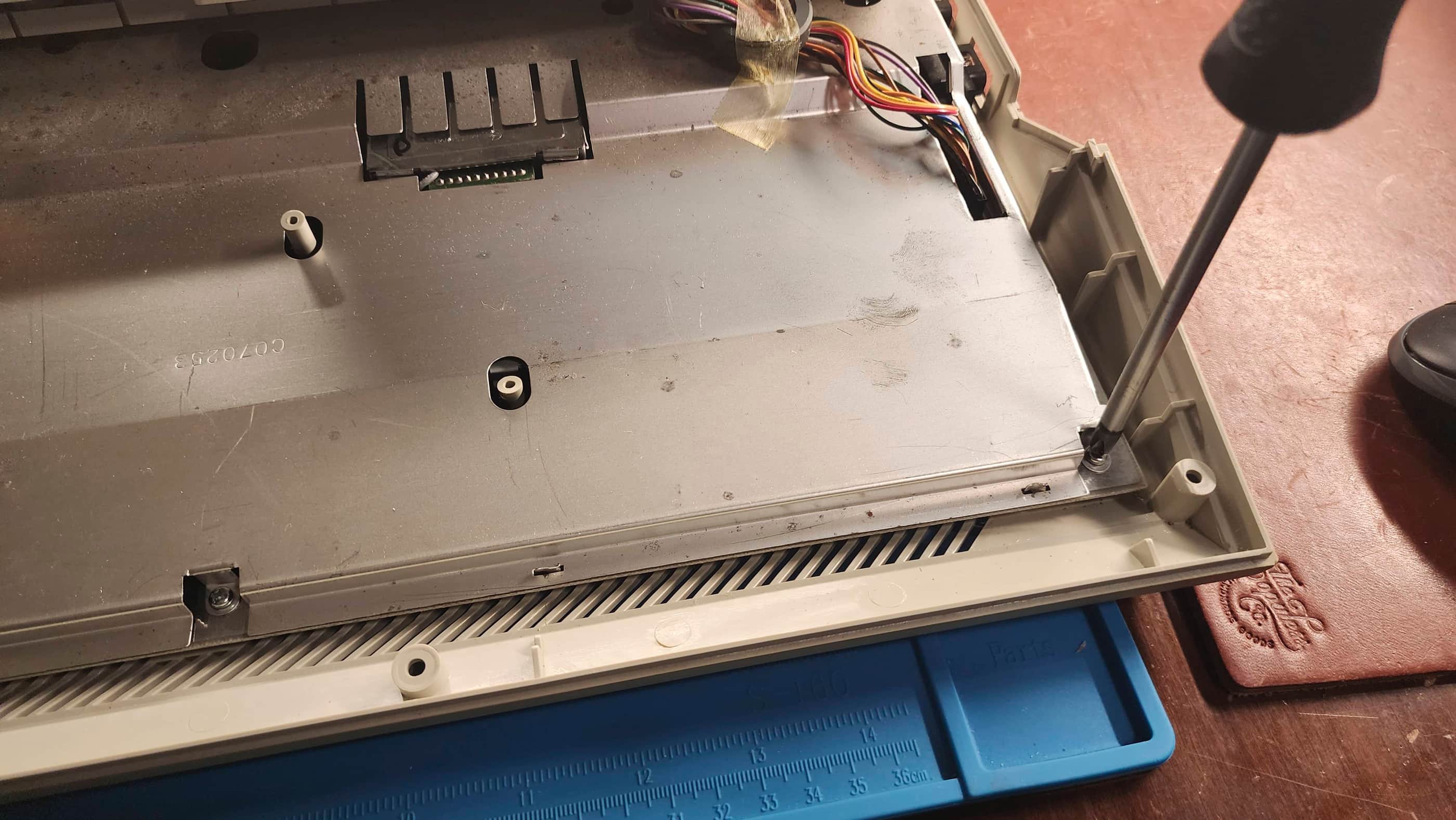
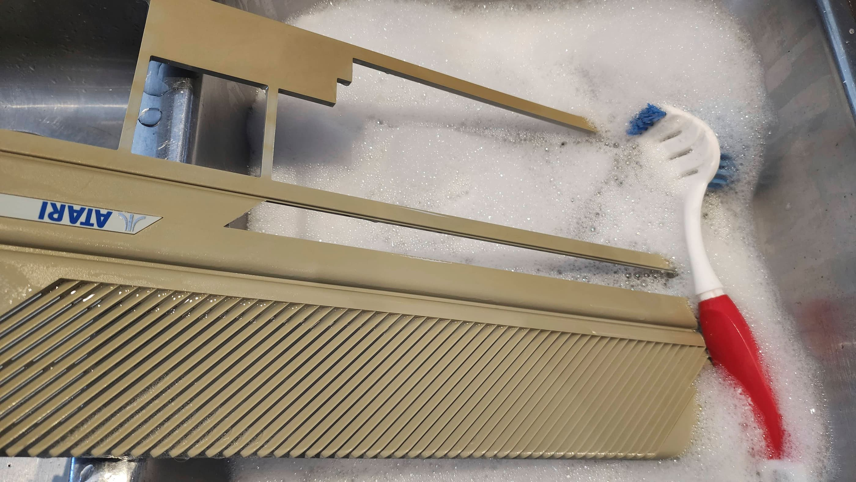
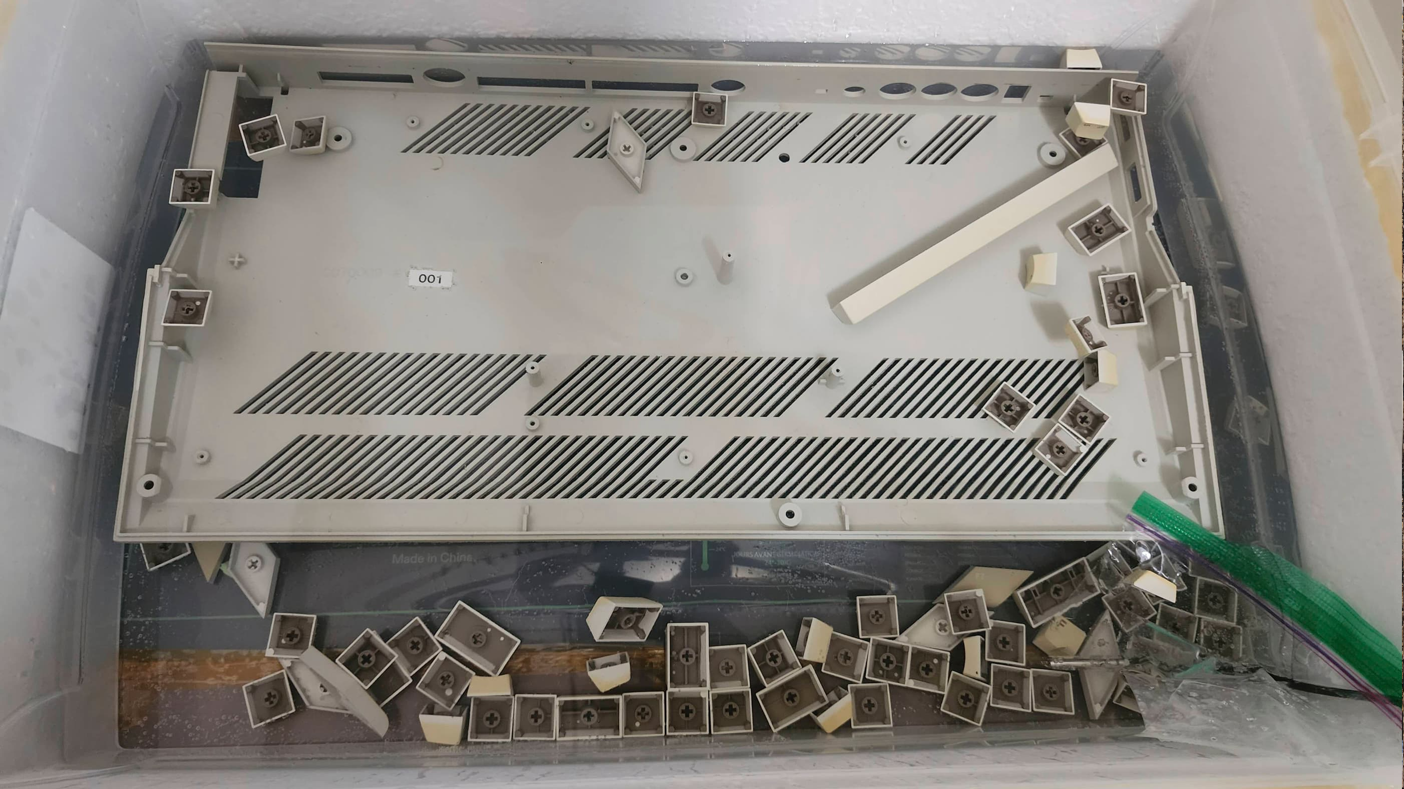
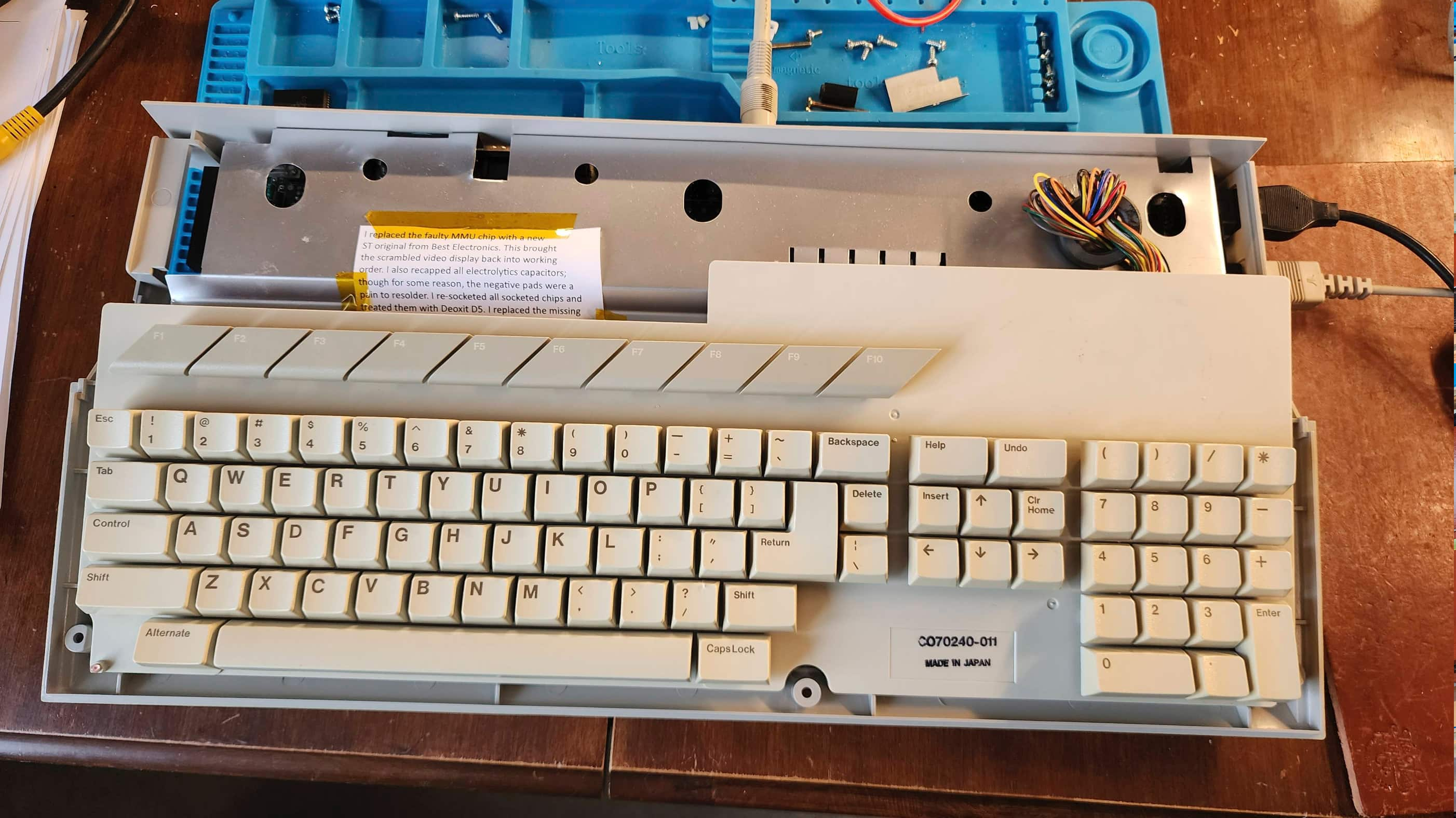
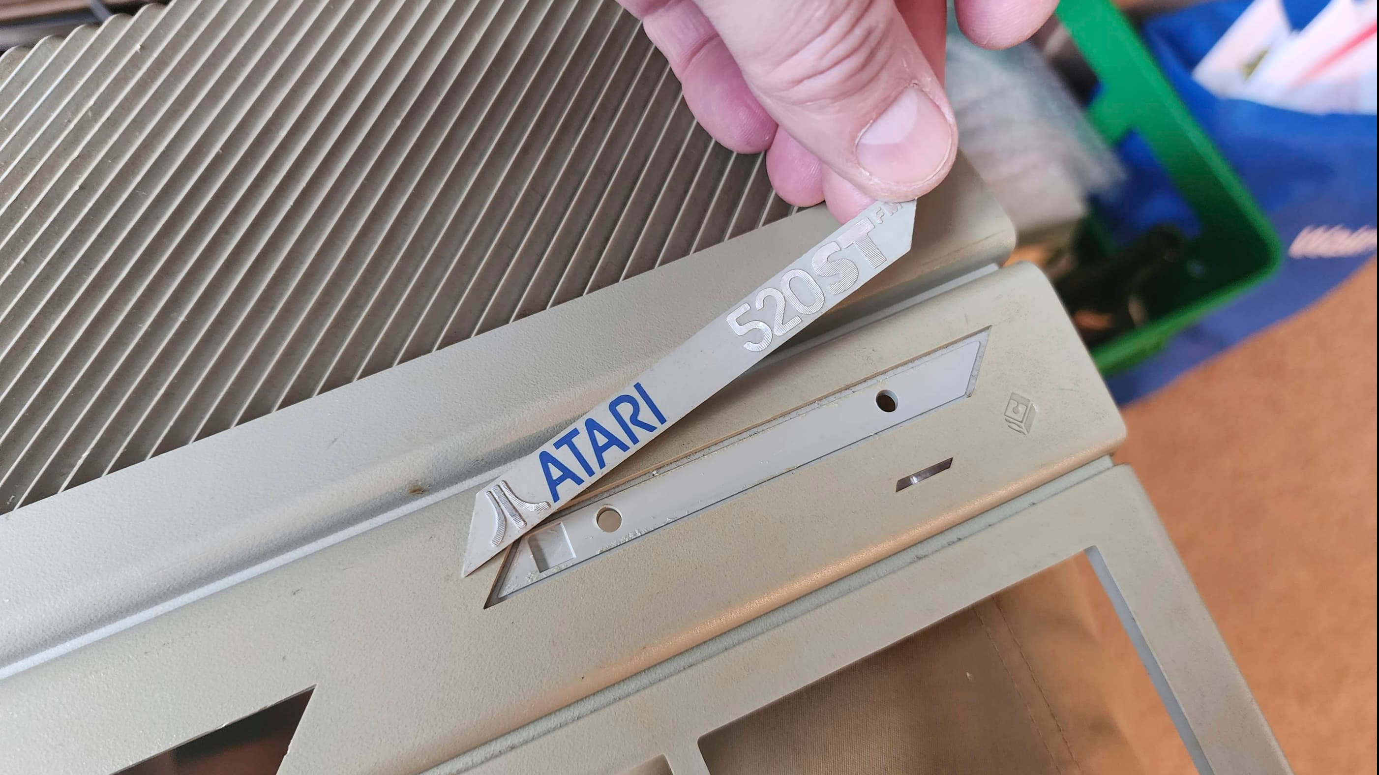
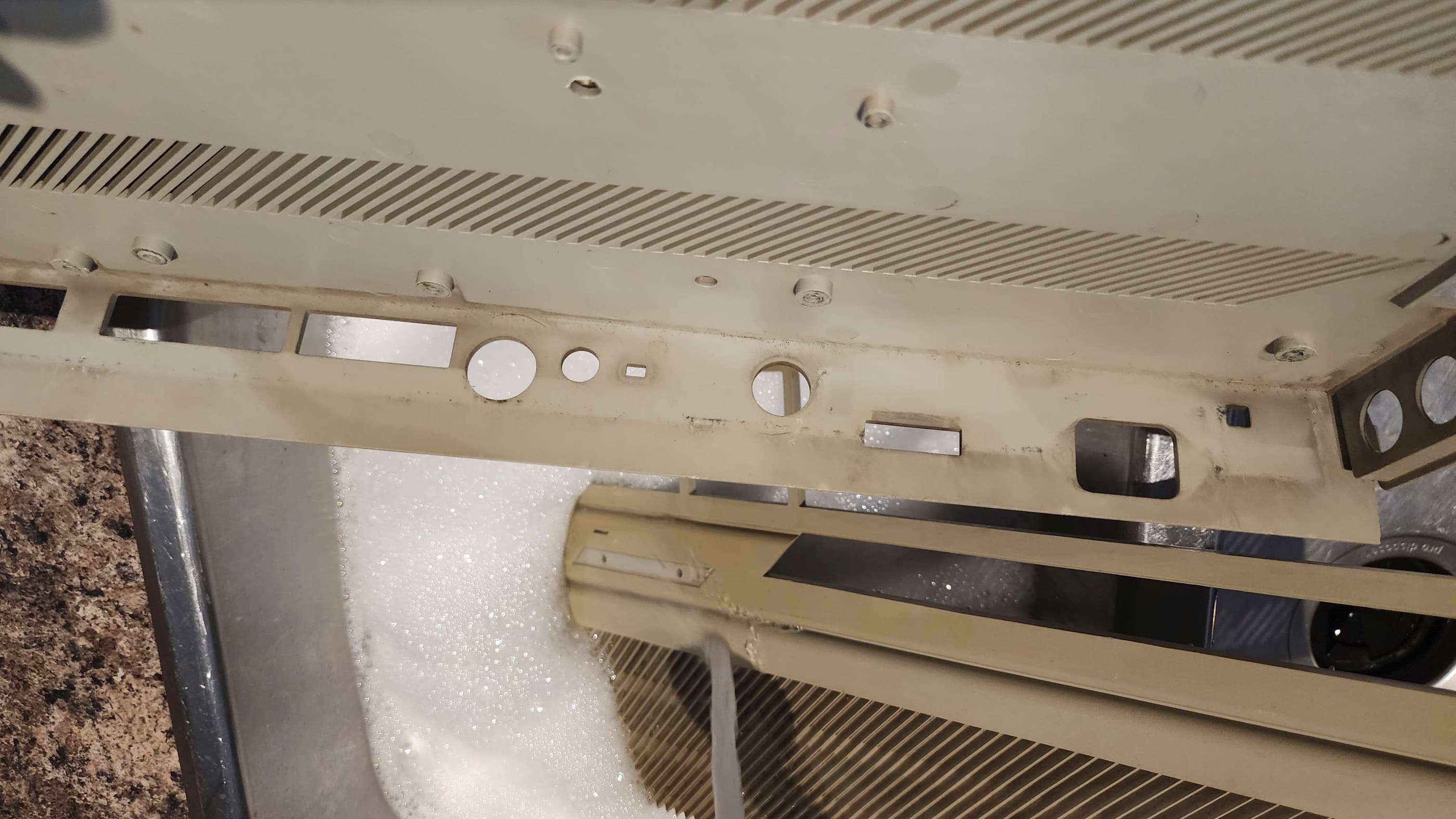
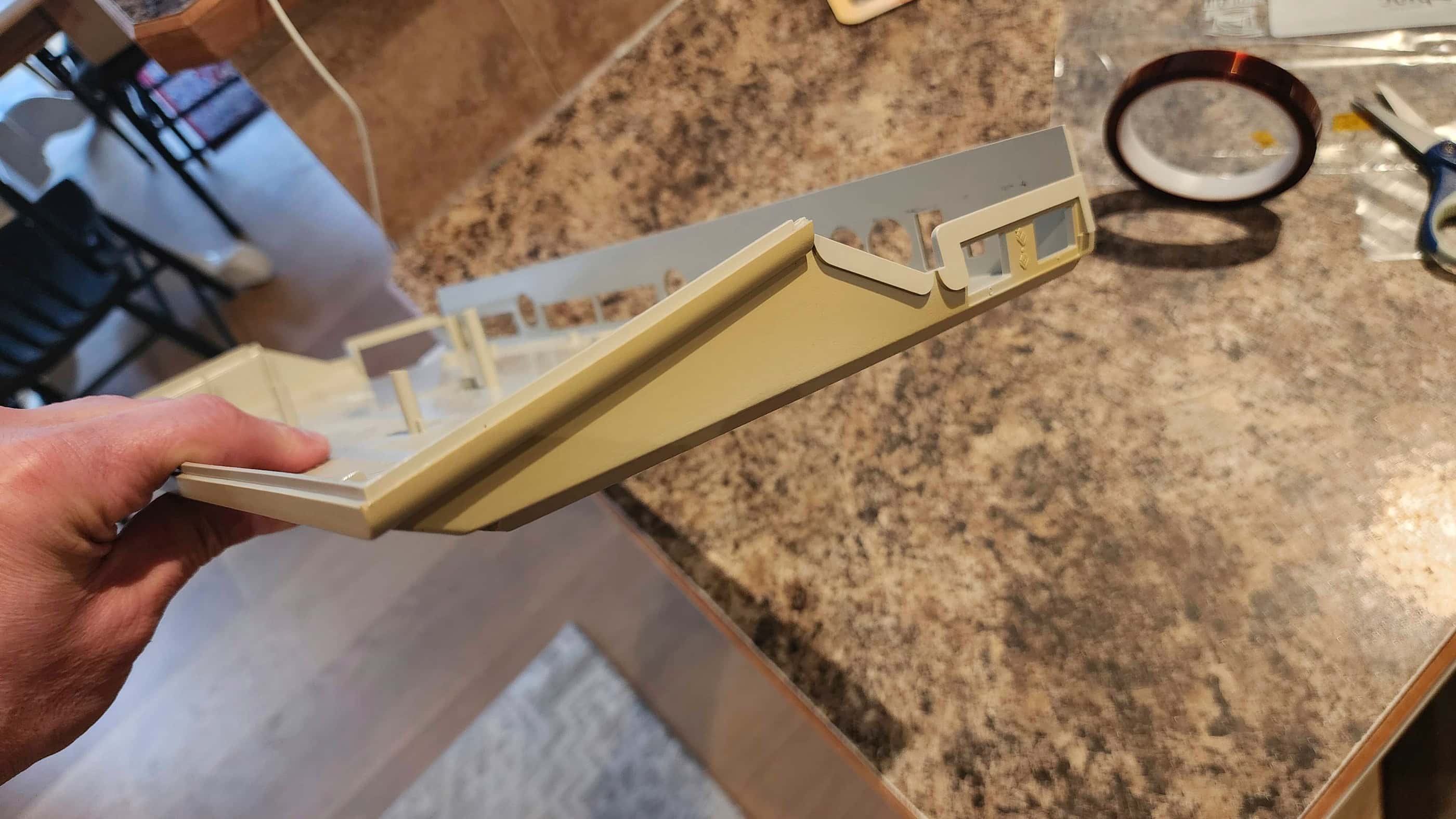
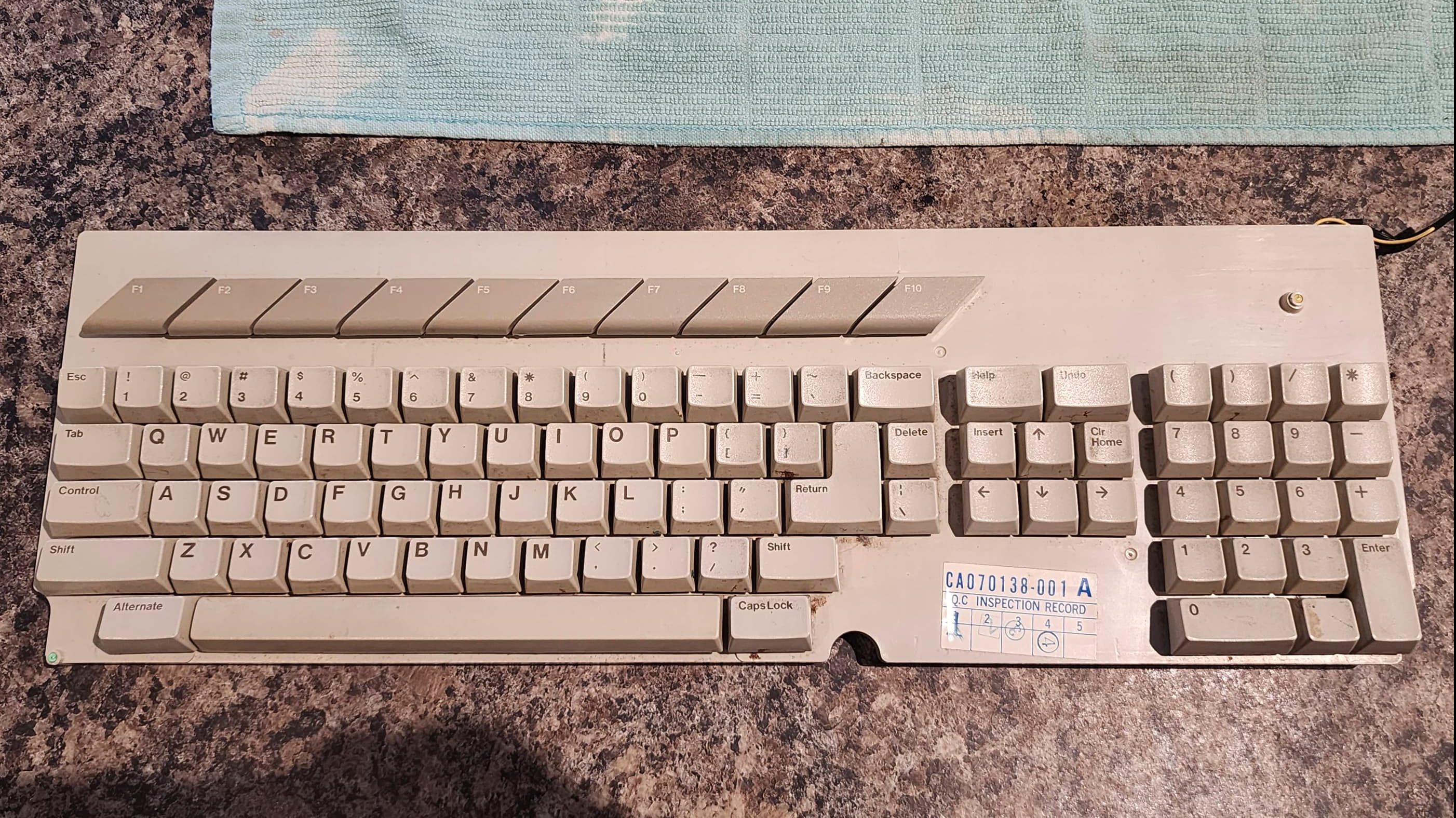
This ST came to me as an ‘untested’ machine that was lacking its PSU and a mouse. The case and the keyboard were also extremely dirty and horribly yellowed. In fact, this was one of the most yellowed systems that I’d ever owned – which made it perfect for my first real foray into retrobrighting. 🙂
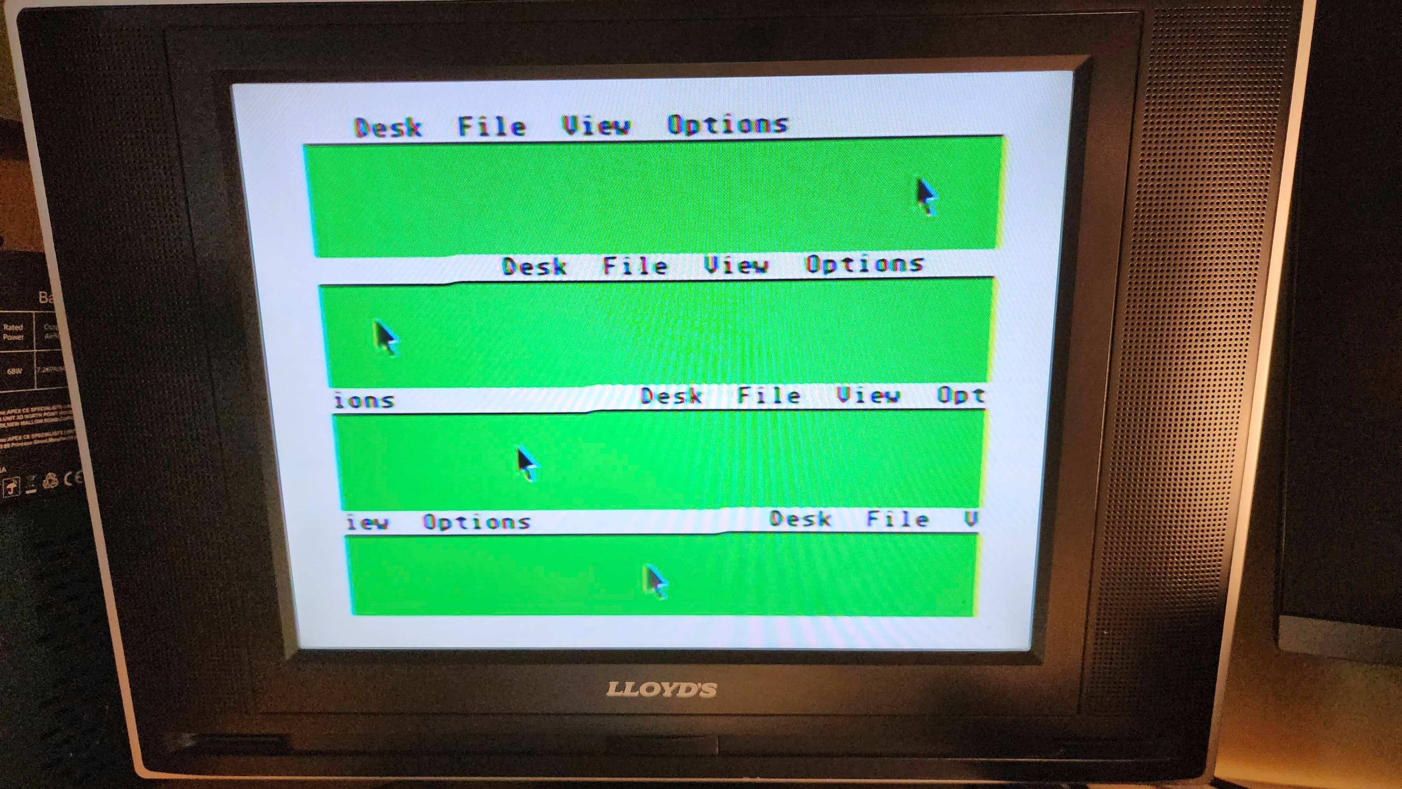
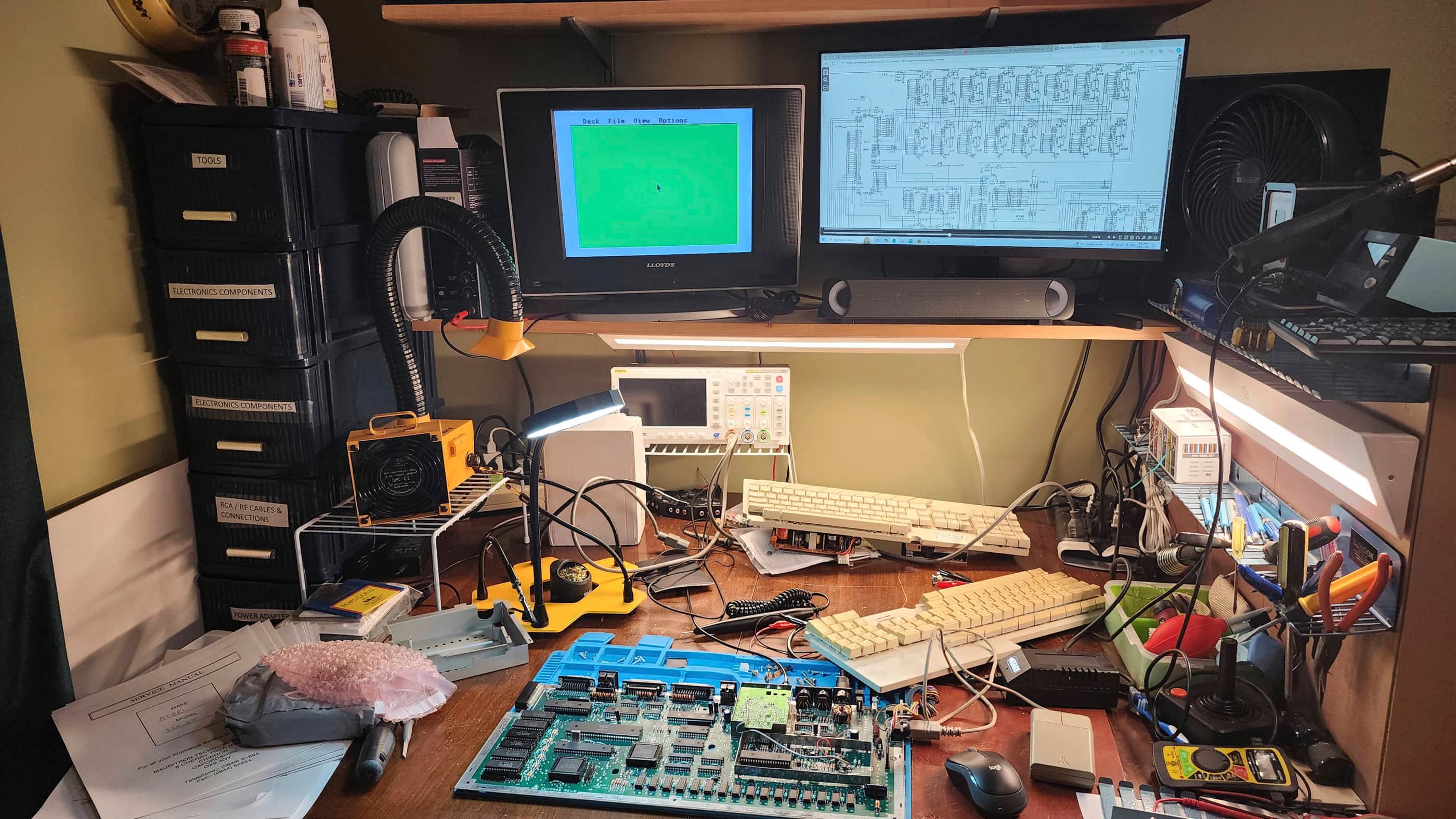
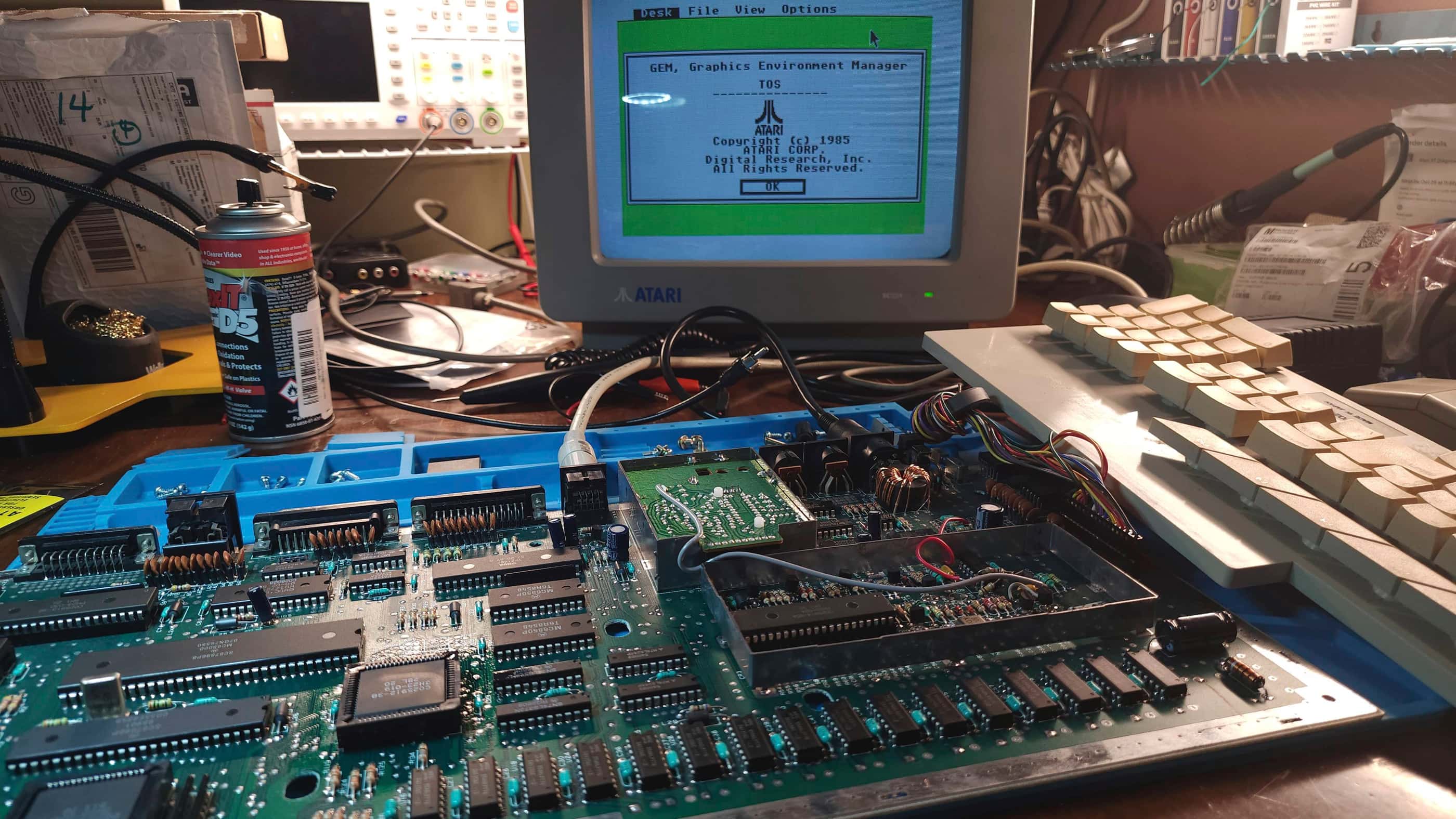
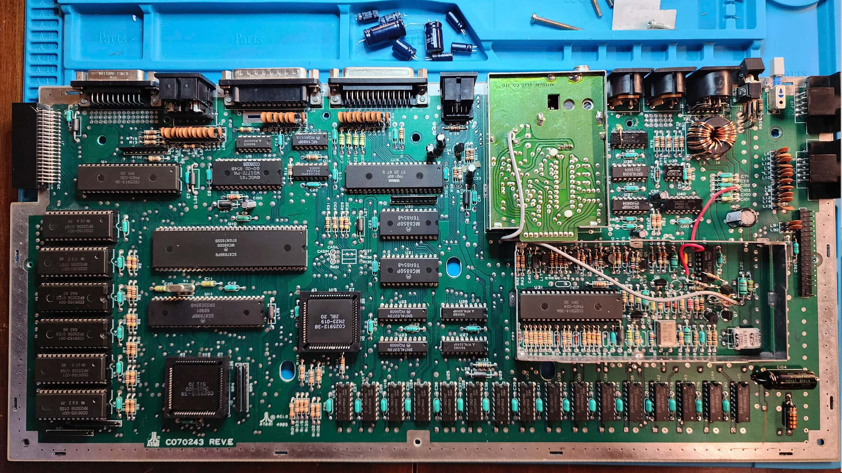
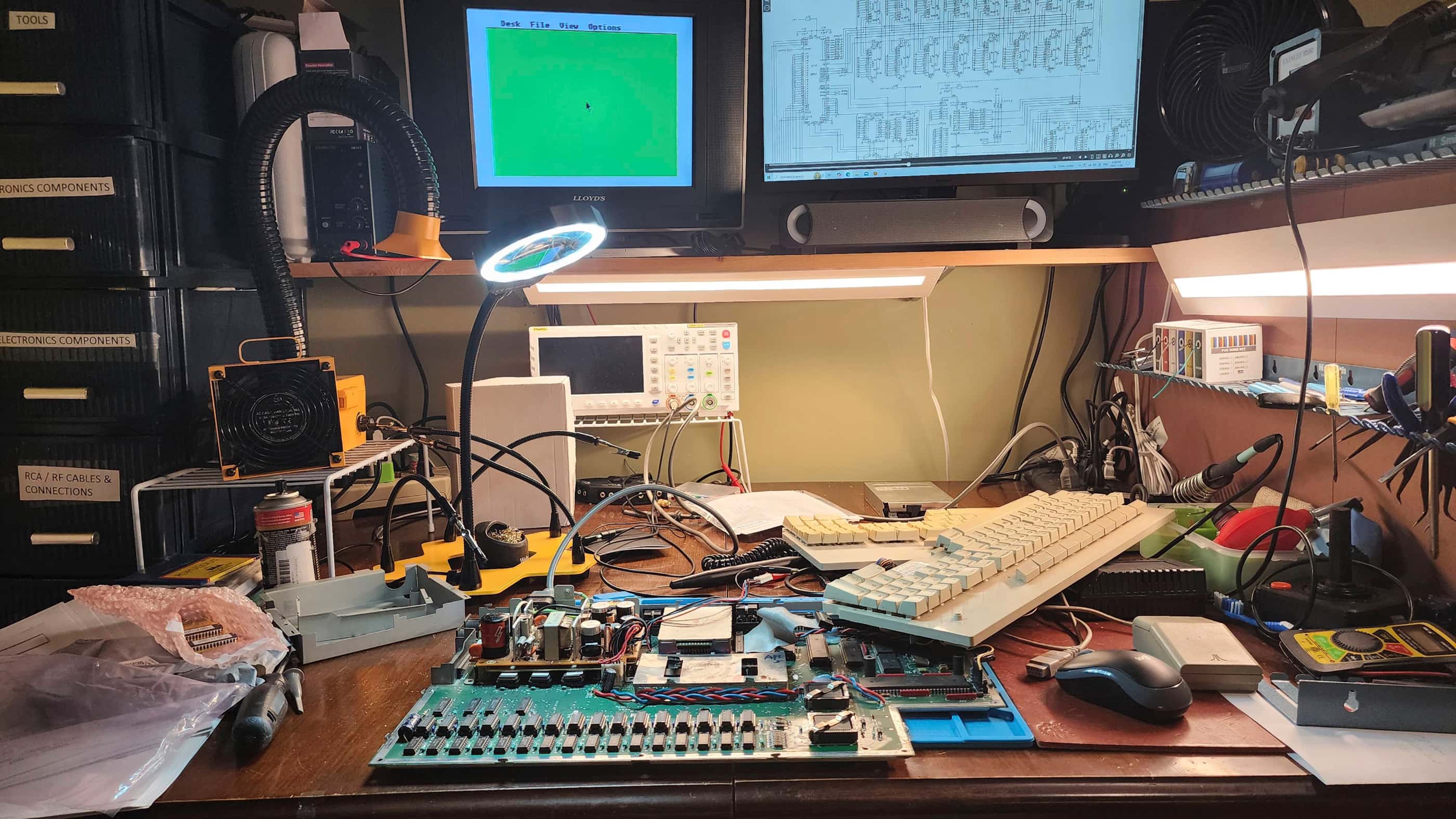
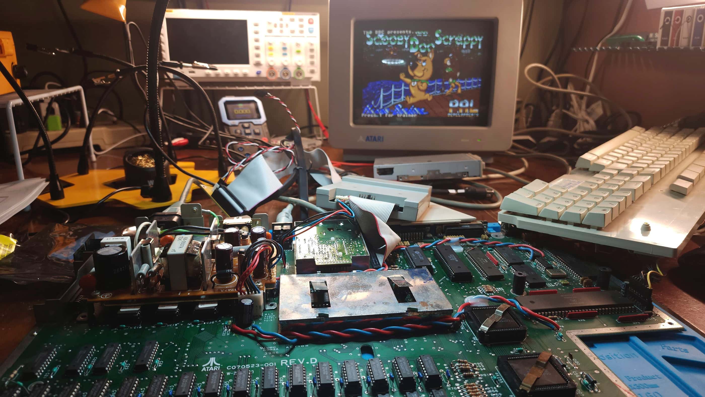
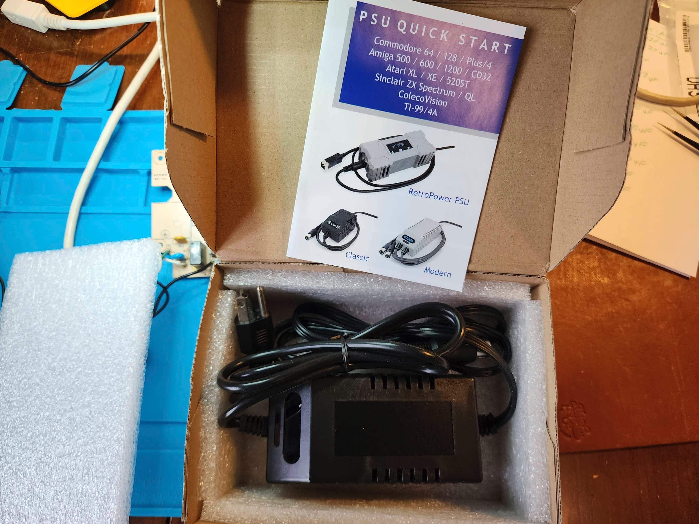
Before I could do anything, I needed to order a PSU from Keelog and pull a mouse from one of my other STs. Once the PSU arrived, I powered up the system and was met with a very interesting display. The GEM desktop display was there, but only the top quarter which was replicated four times on the screen. This was really weird, and when I moved the mouse, I had four pointers.
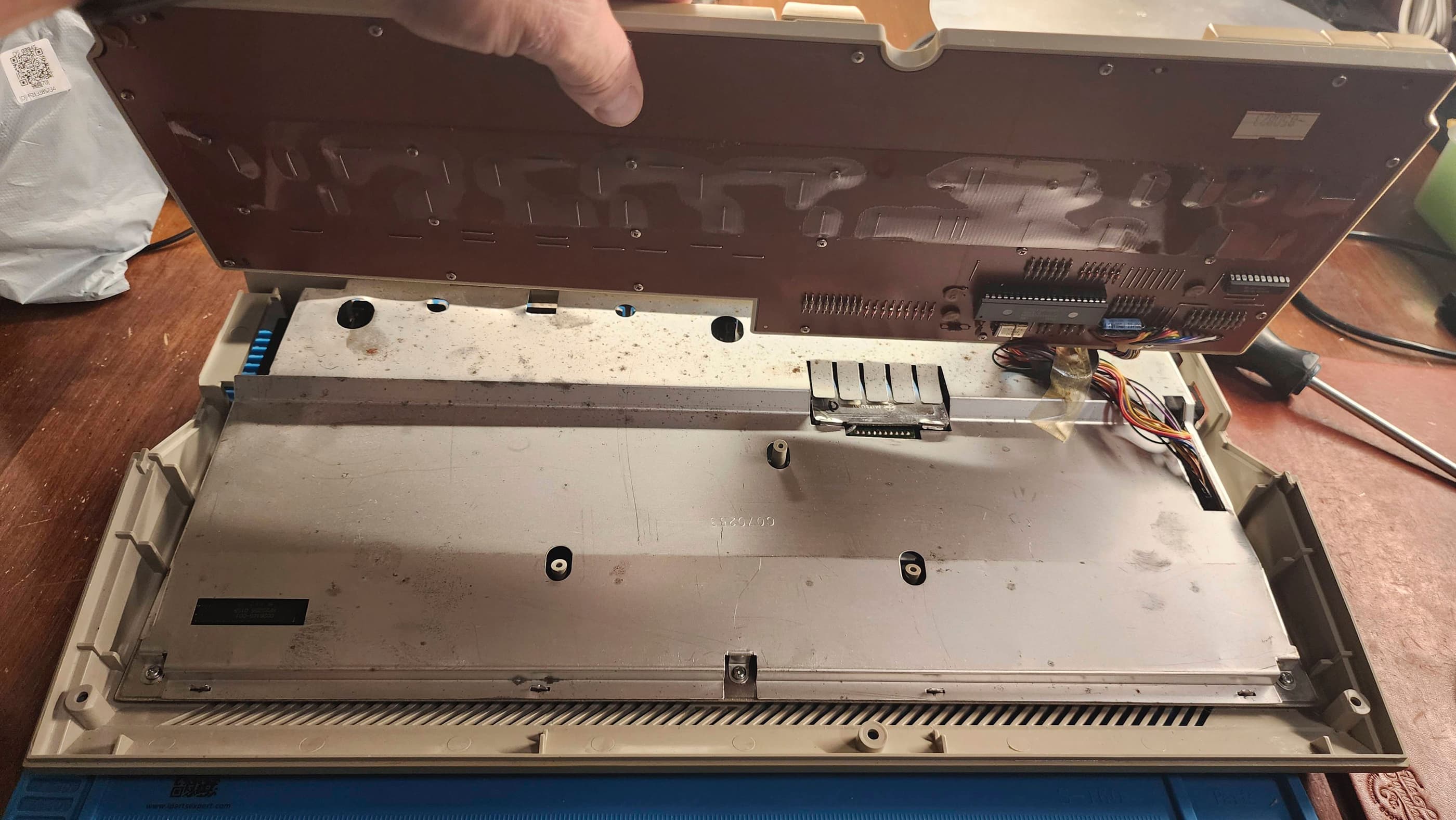
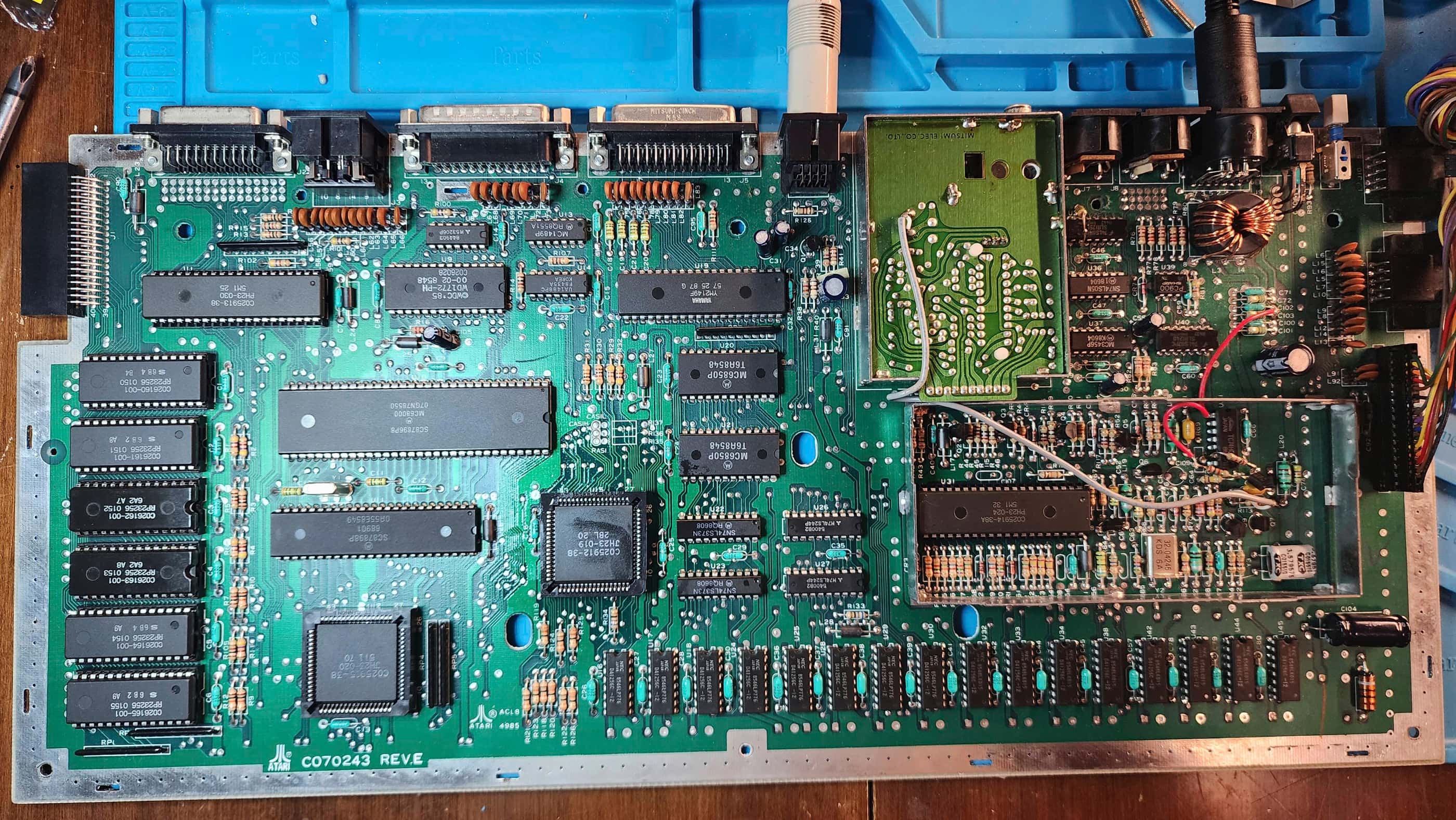
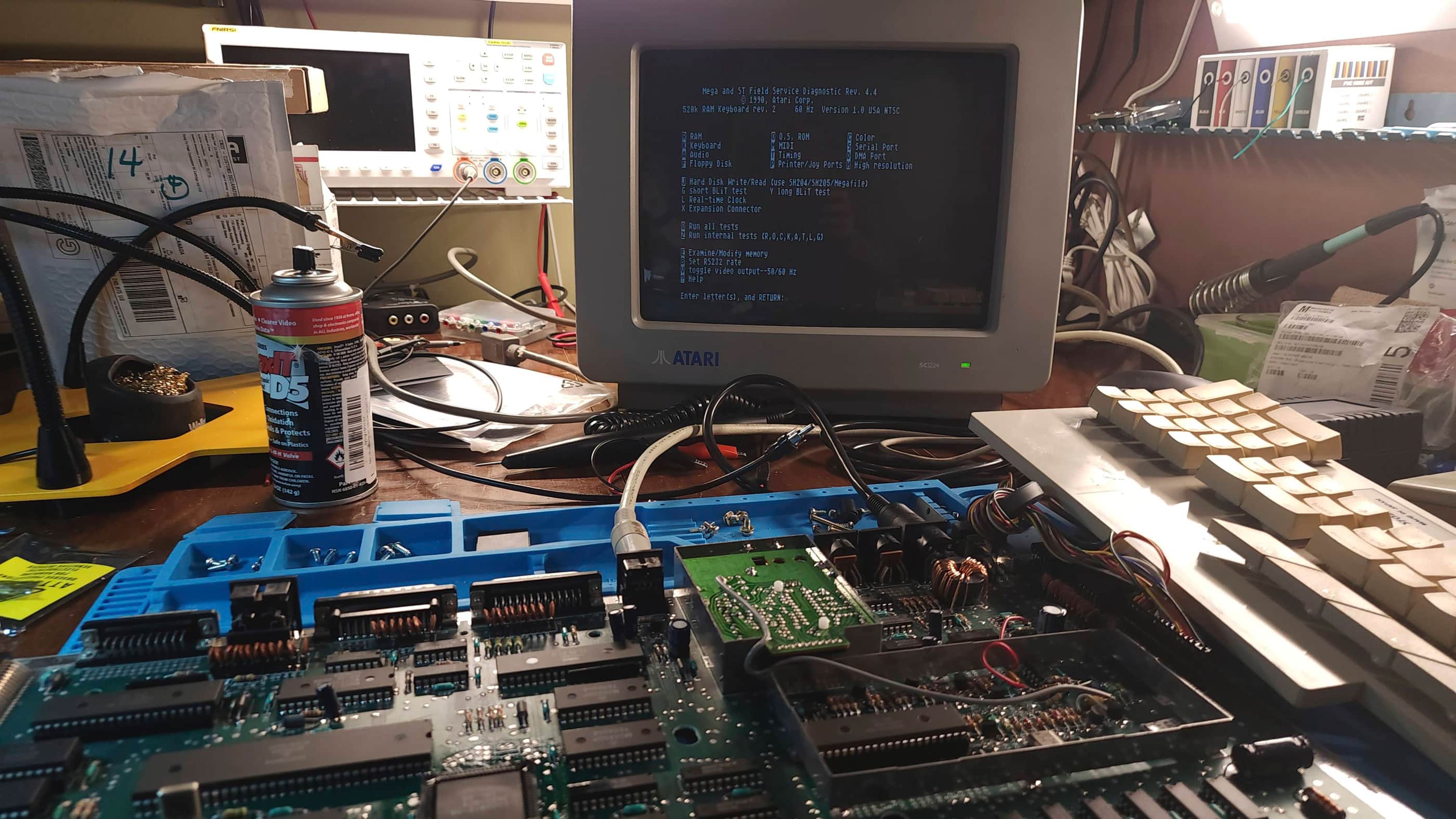
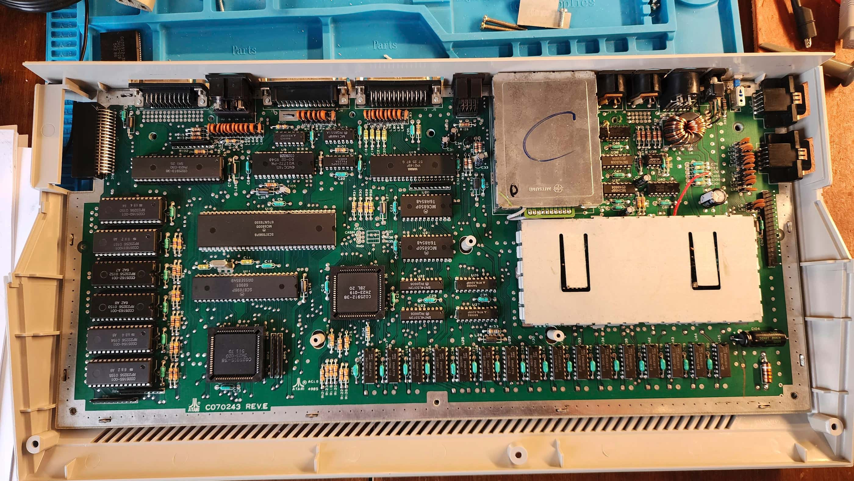
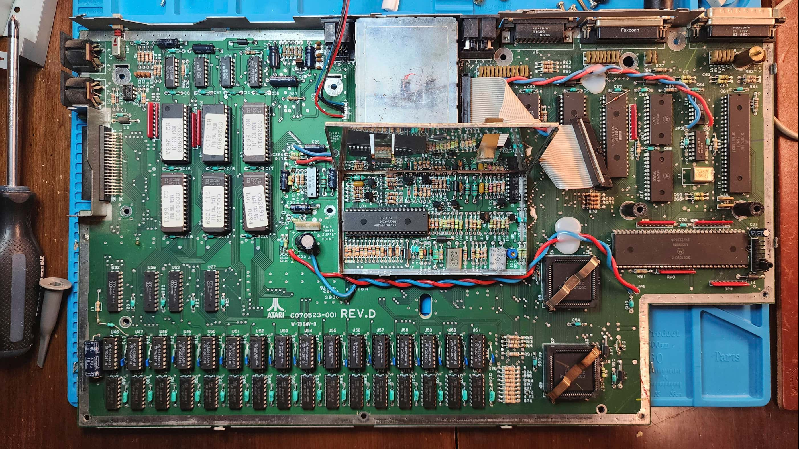
My first thought was to reseat all of the socketed chips on the board as STs were notorious for requiring the ‘Atari Drop’ where the machine would be dropped from a height of approximately 6” onto a hard surface. The resulting impact would reseat all of the chips and fix many issues, including a white display screen. However, after reseating and applying Deoxit D5 to all of the socketed chips, nothing had changed. I still had the weird quad display issue. I couldn’t even use my Atari ST diagnostic cartridge because it also displayed only the top quarter of the screen x 4.
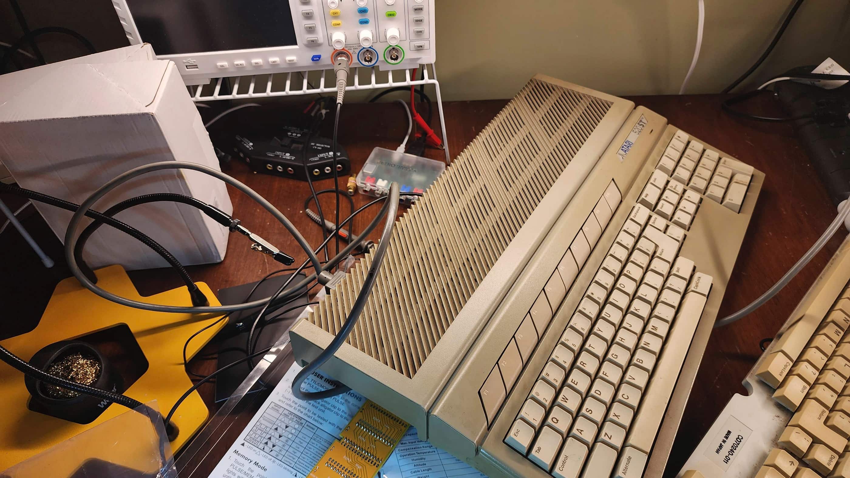
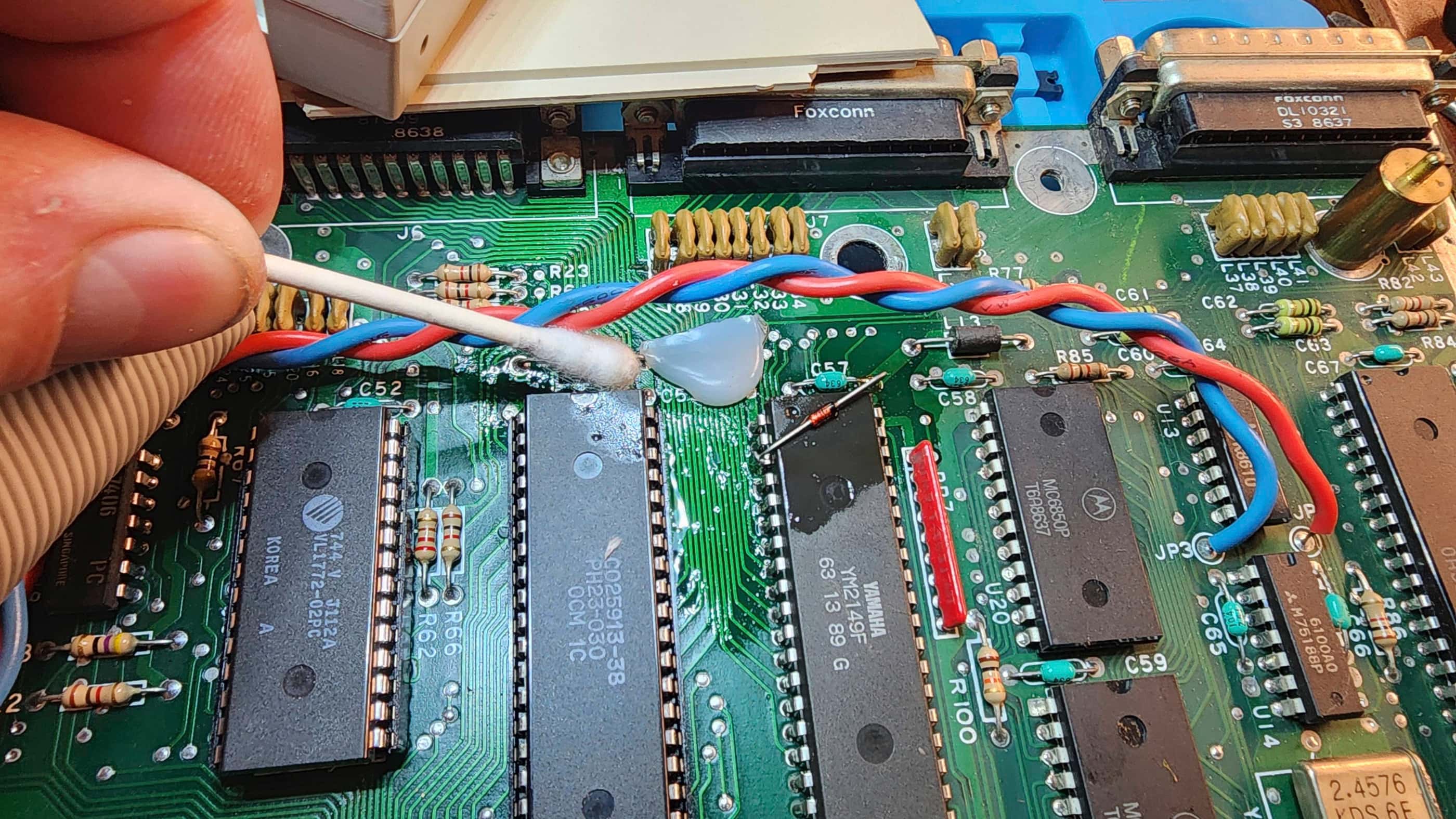
My first line of thinking was to check the video shifter chip with the oscilloscope with a focus on the HSync and VSync. Not finding much, though most likely due to my inexperience with identifying deviations in wave patterns, I then focused on the TOS ROM chips and the DRAM. Using a logic probe and my multimeter, I could not identify anything out of the ordinary.
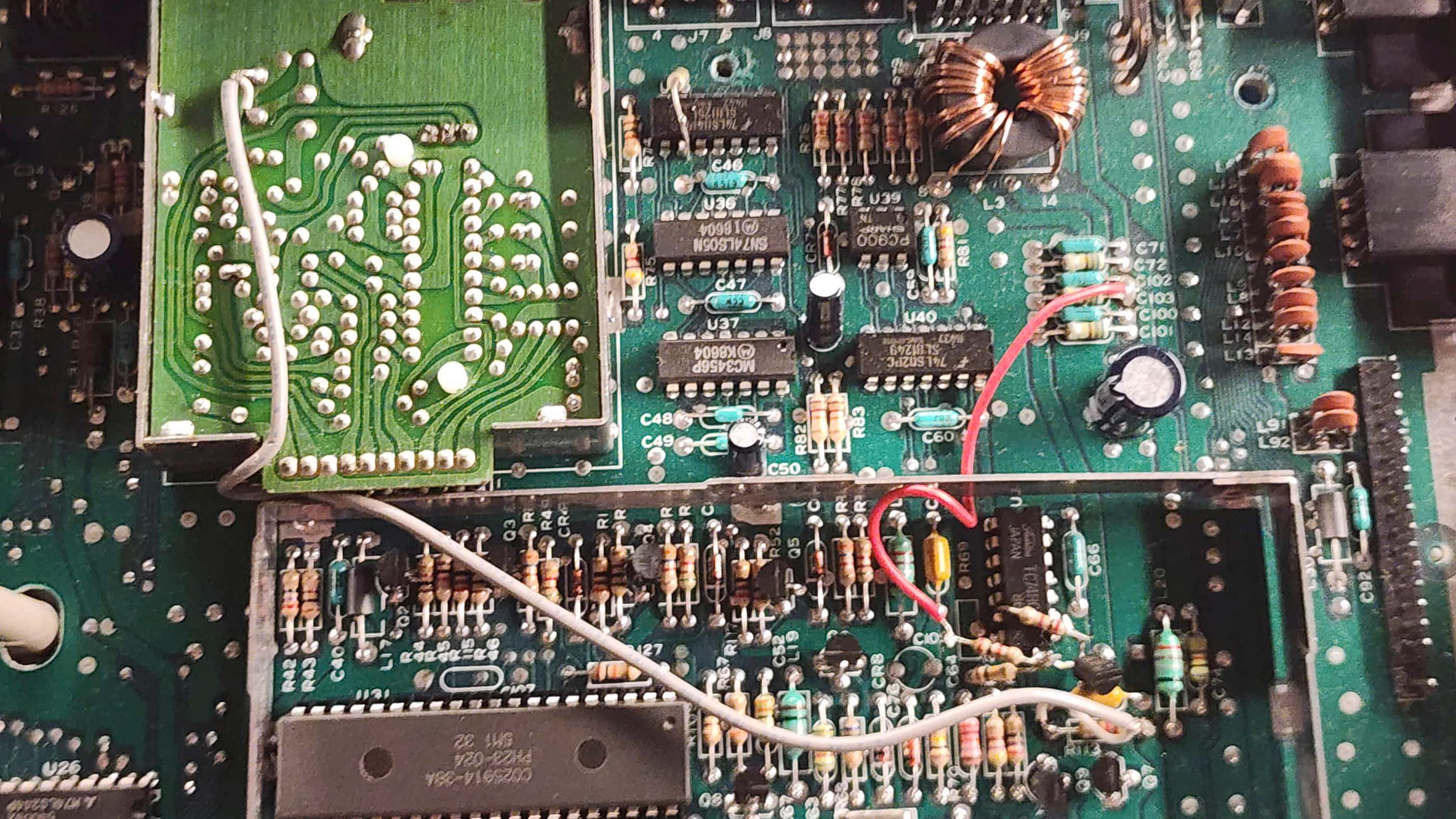
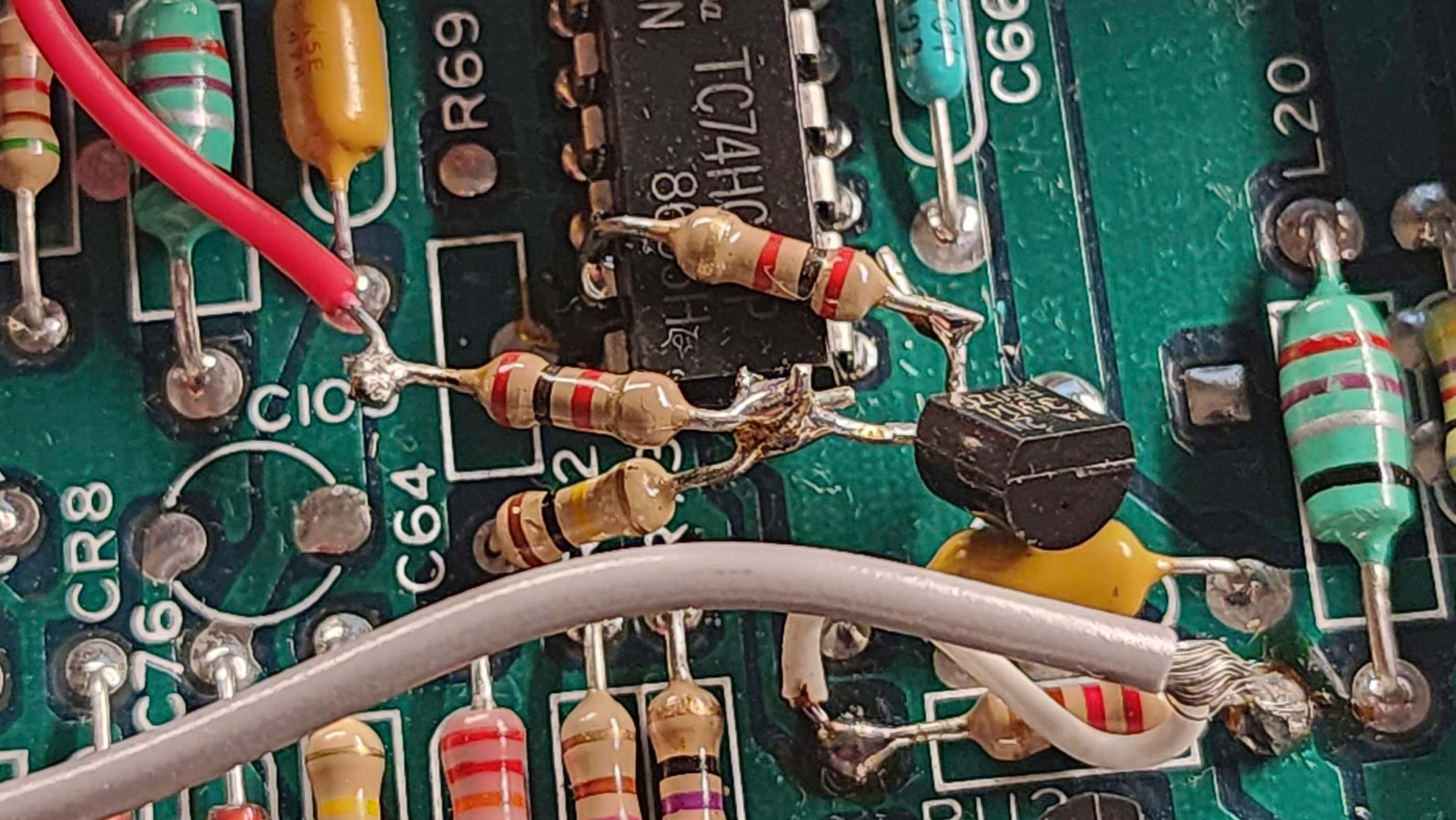
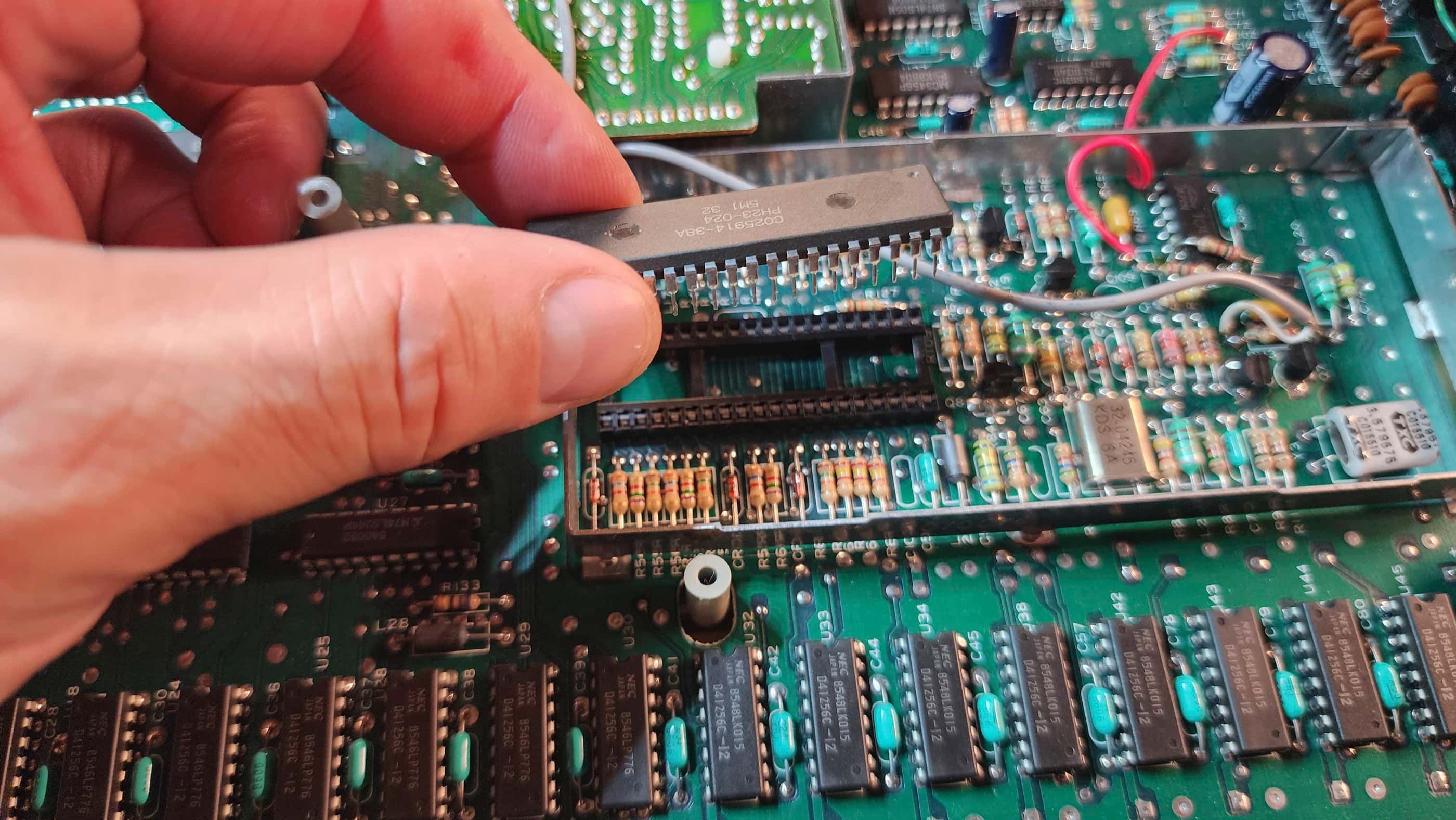
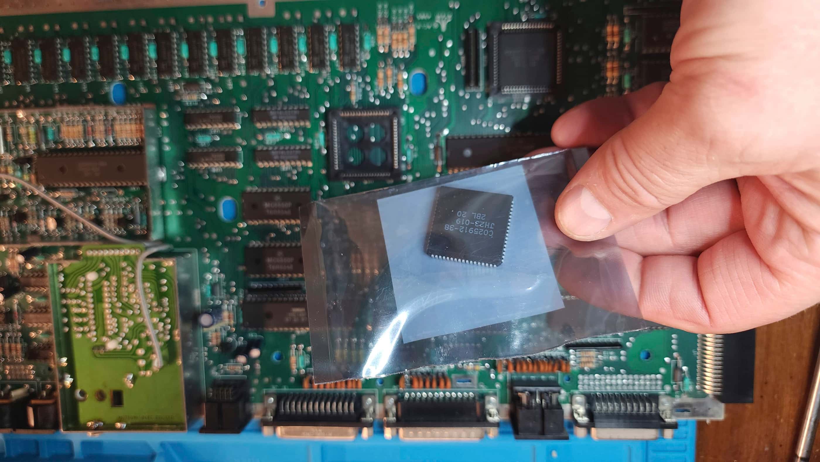
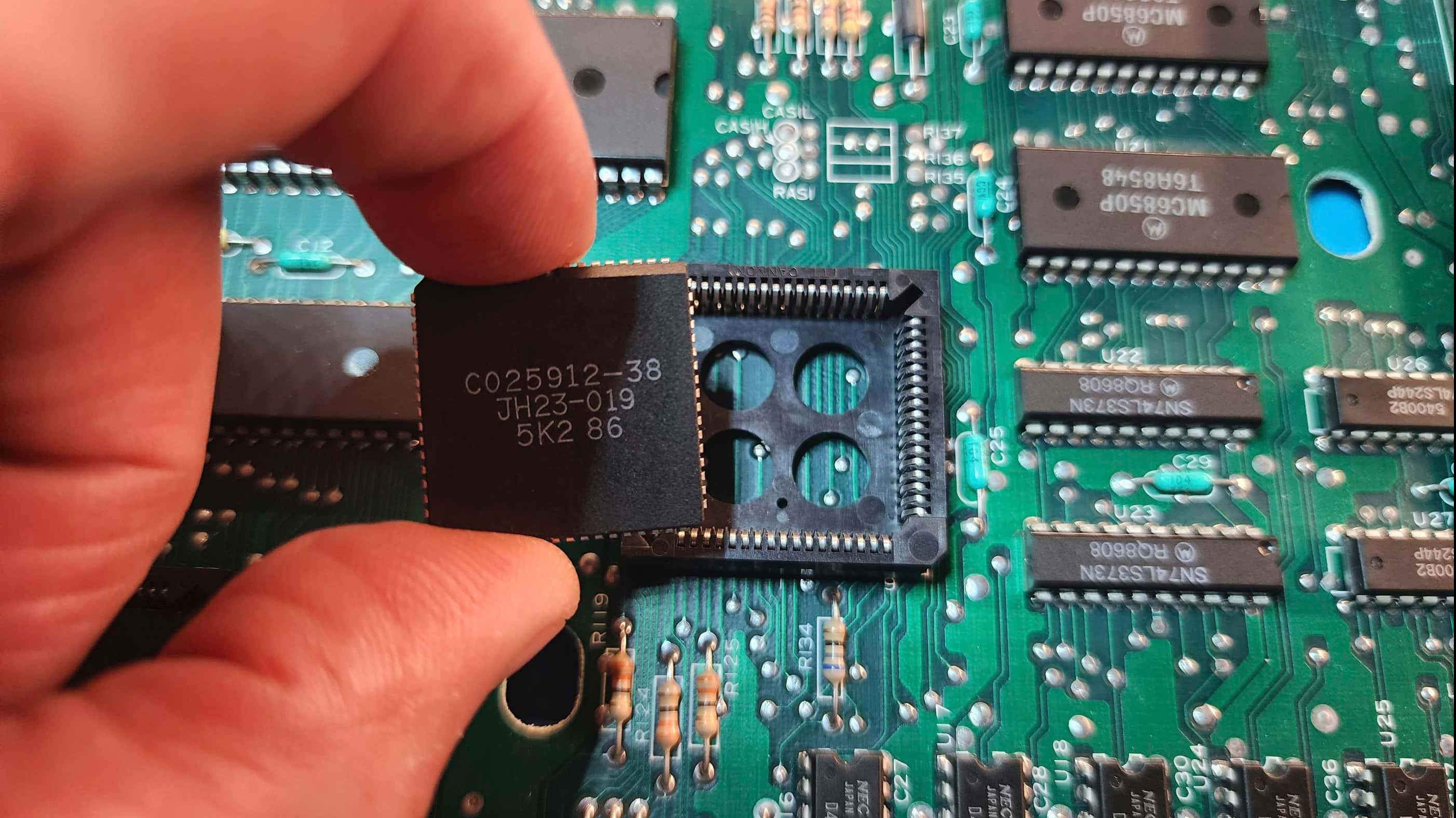
That’s when I began to focus on the GLU chip and the MMU. I knew that my 1040 STFM worked and that my 520 STFM partially worked, so I decided to try swapping chips. Immediately after replacing the MMU with the one from my 520 STFM, the video issue resolved itself and I had a normal display. My next step was to order a replacement MMU from Best Electronics which still has new old stock of the Ricoh-made chips.
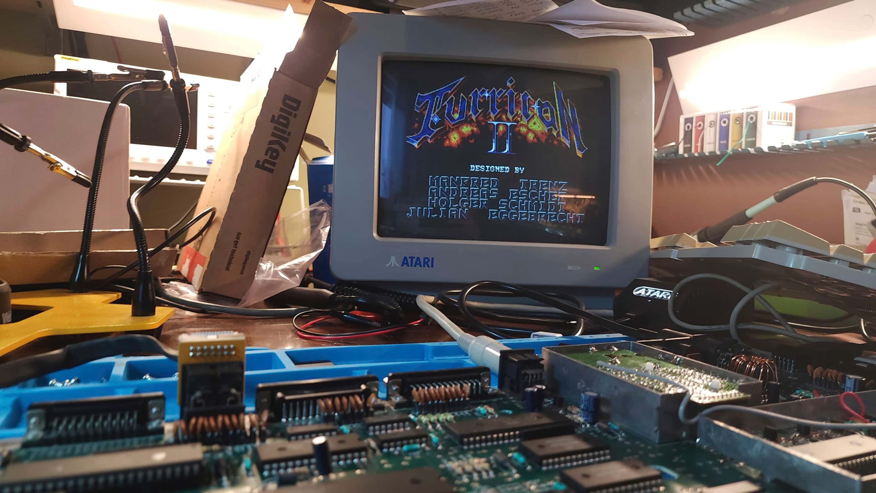
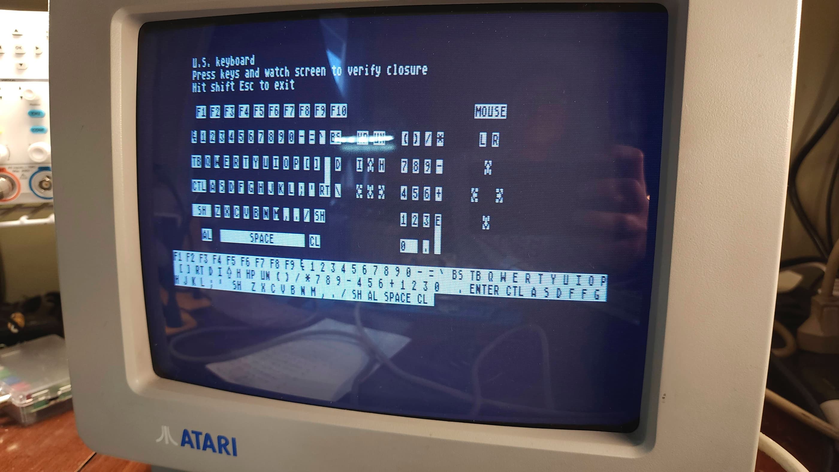
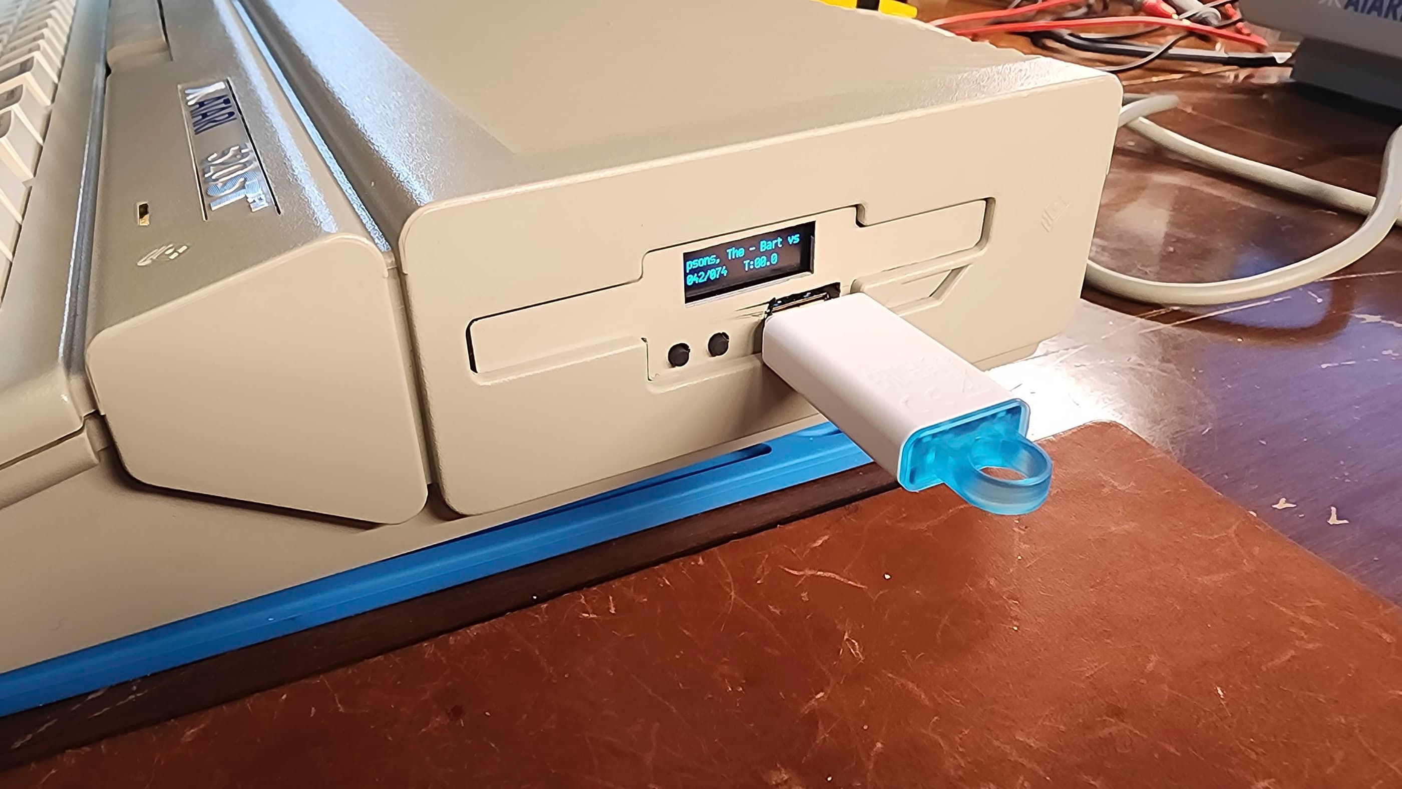
While waiting for the new MMU to arrive, I turned my attention to preparing an external Gotek drive to use with the computer and also prepping it for retrobrighting. Once the new MMU chip arrived, I was able to run my ST diagnostic cartridge and everything else appeared to be working. Not being able to let sleeping dogs lie, I re-capped the board and then hooked up my Gotek and began to test some games and programs.
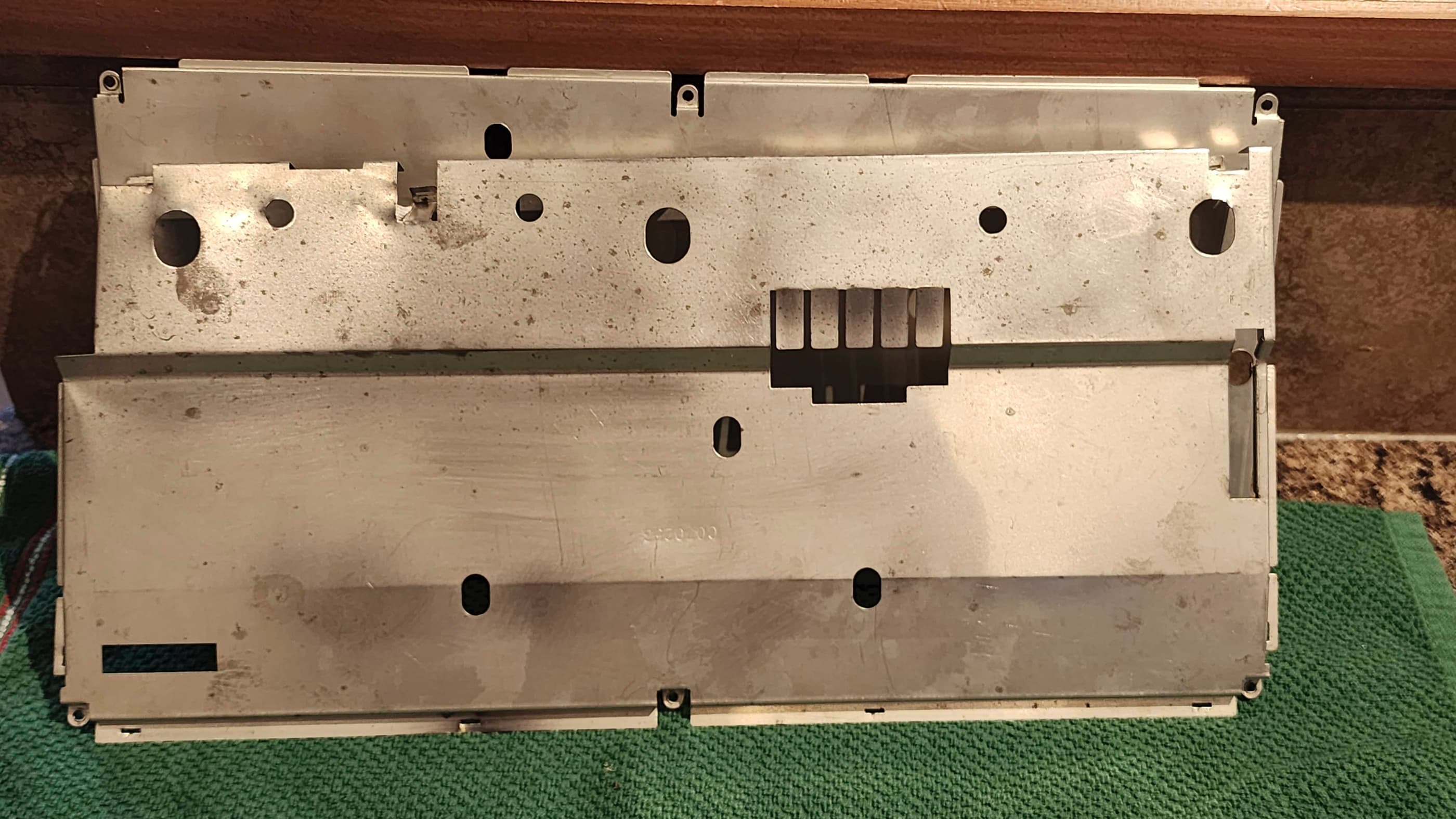
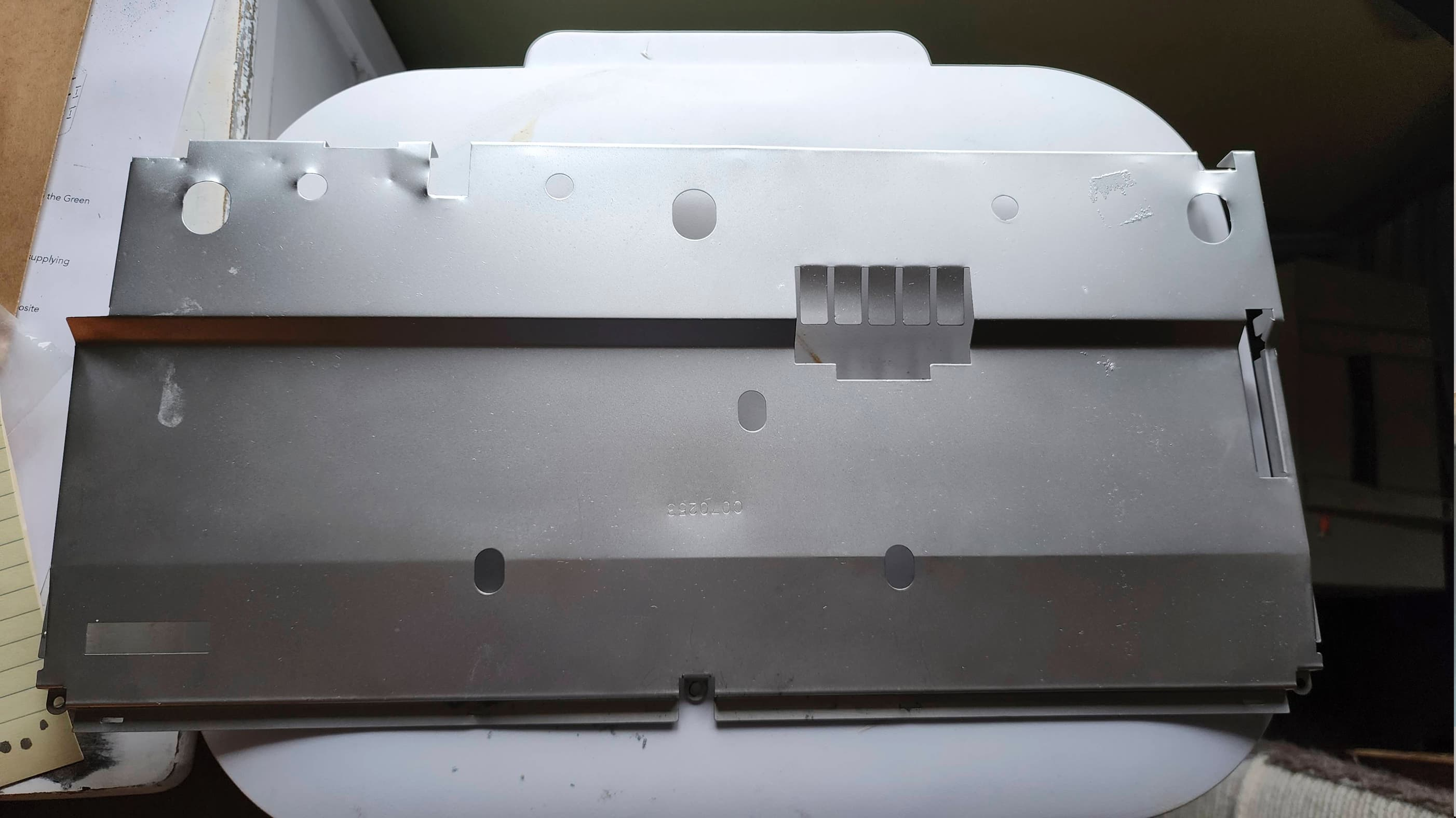
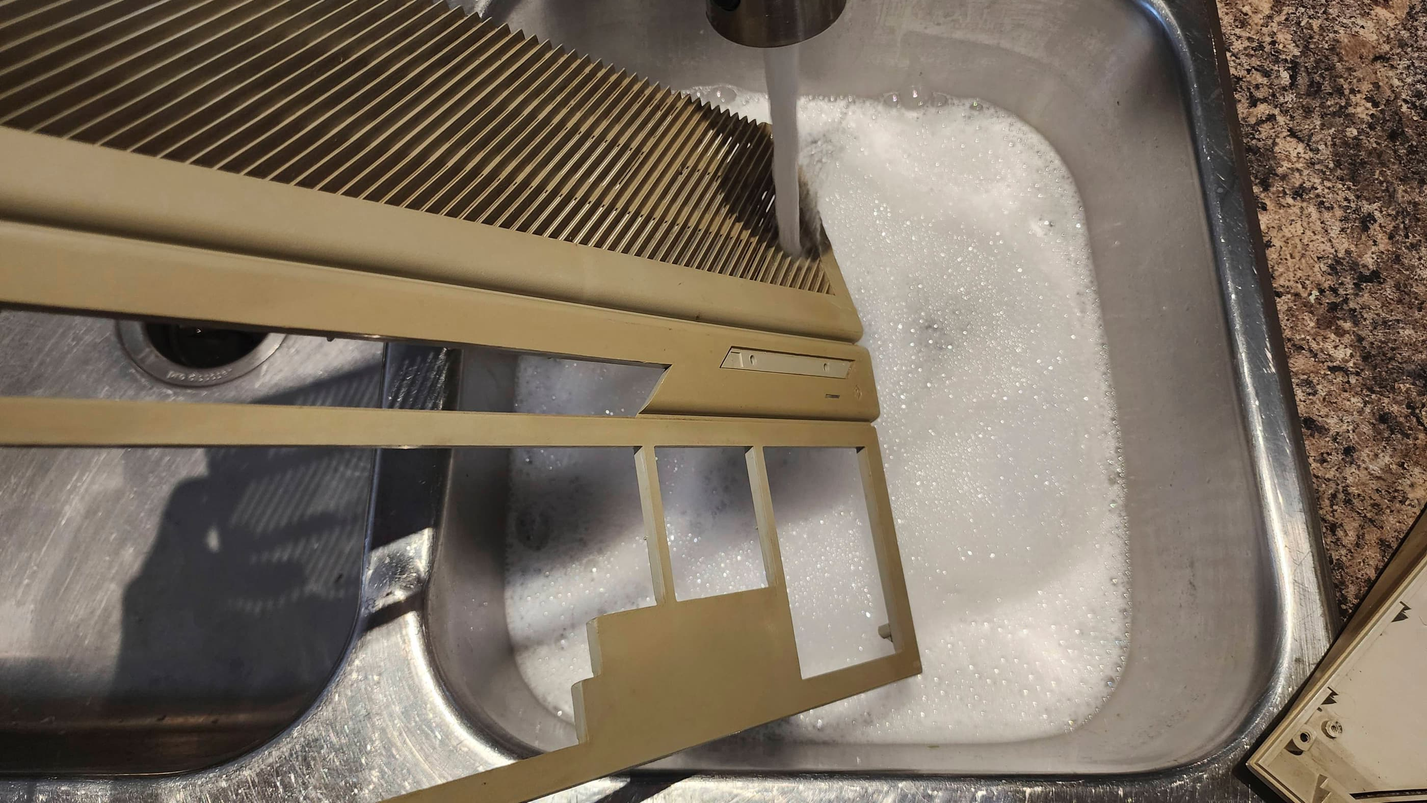
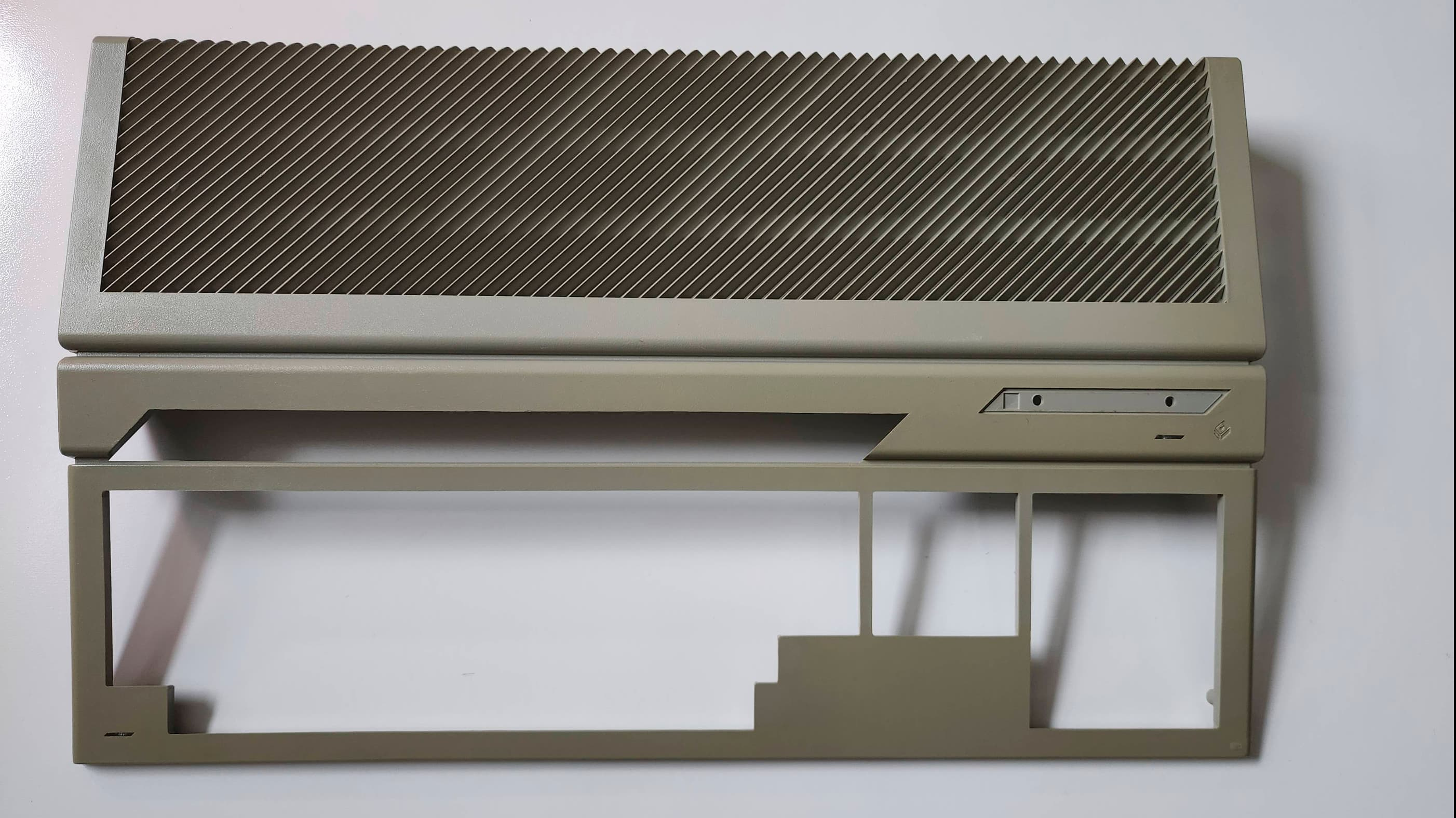
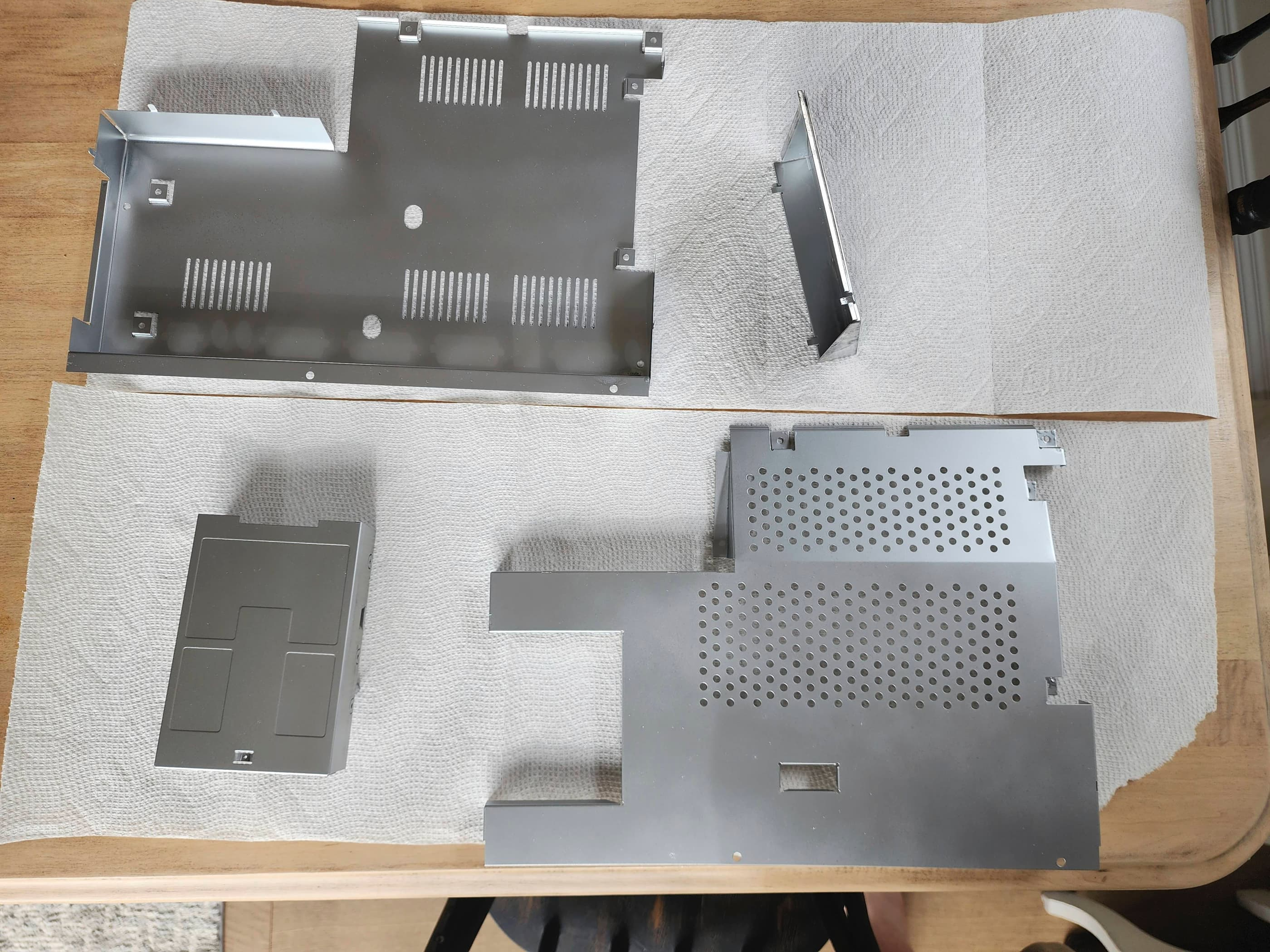
After making sure everything was working, I then turned my attention to the machine’s cosmetic appearance. I sanded out the rust spots on the top part of the RF shielding and applied a light coat of silver Rustoleum. It was now time to deal with the horribly yellowed case and keyboard and since this would be my first major attempt with the retrobrighting process, I was very thankful for Hey Birt!’s video on the facts and myths of retrobrighting.
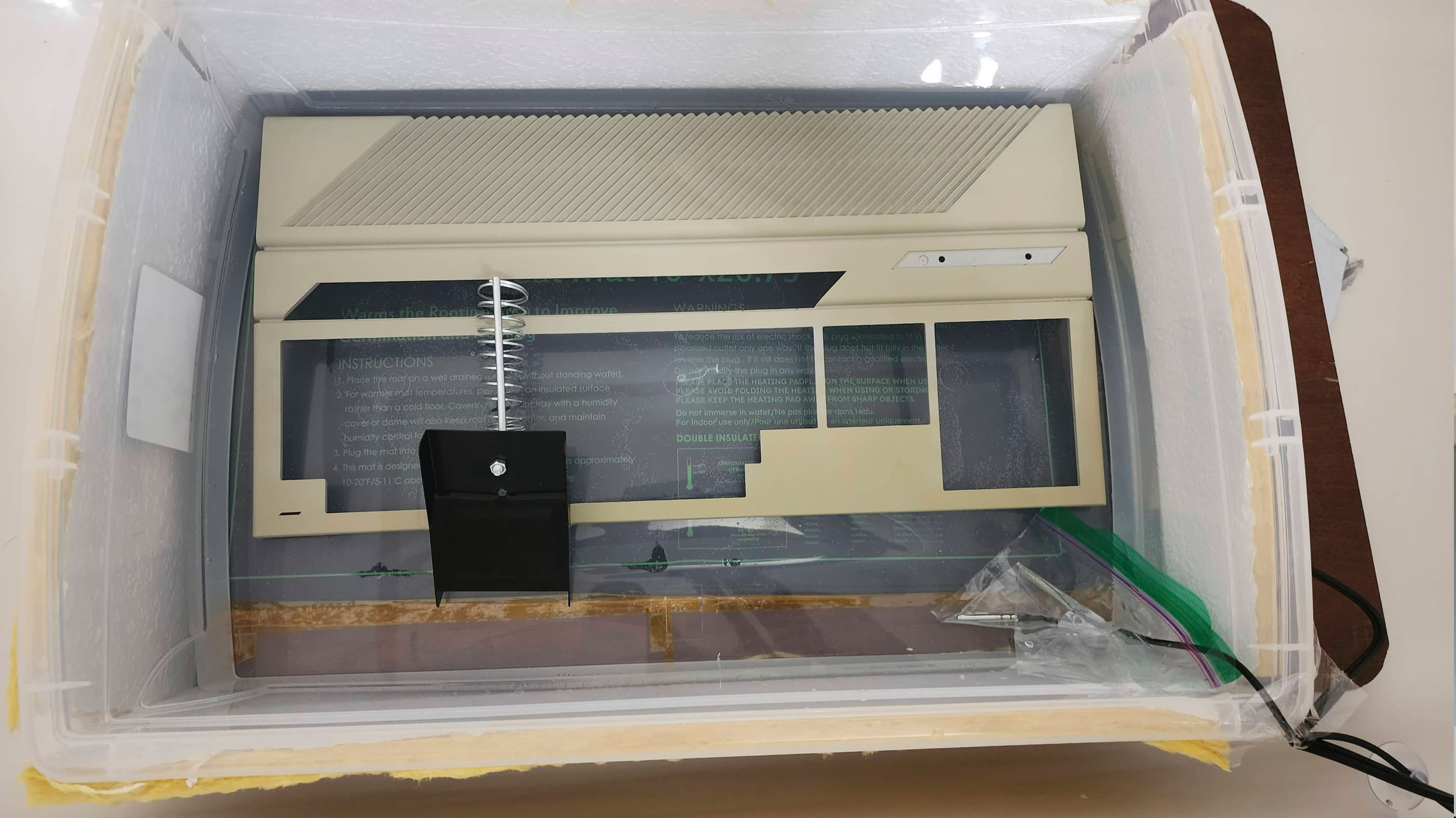
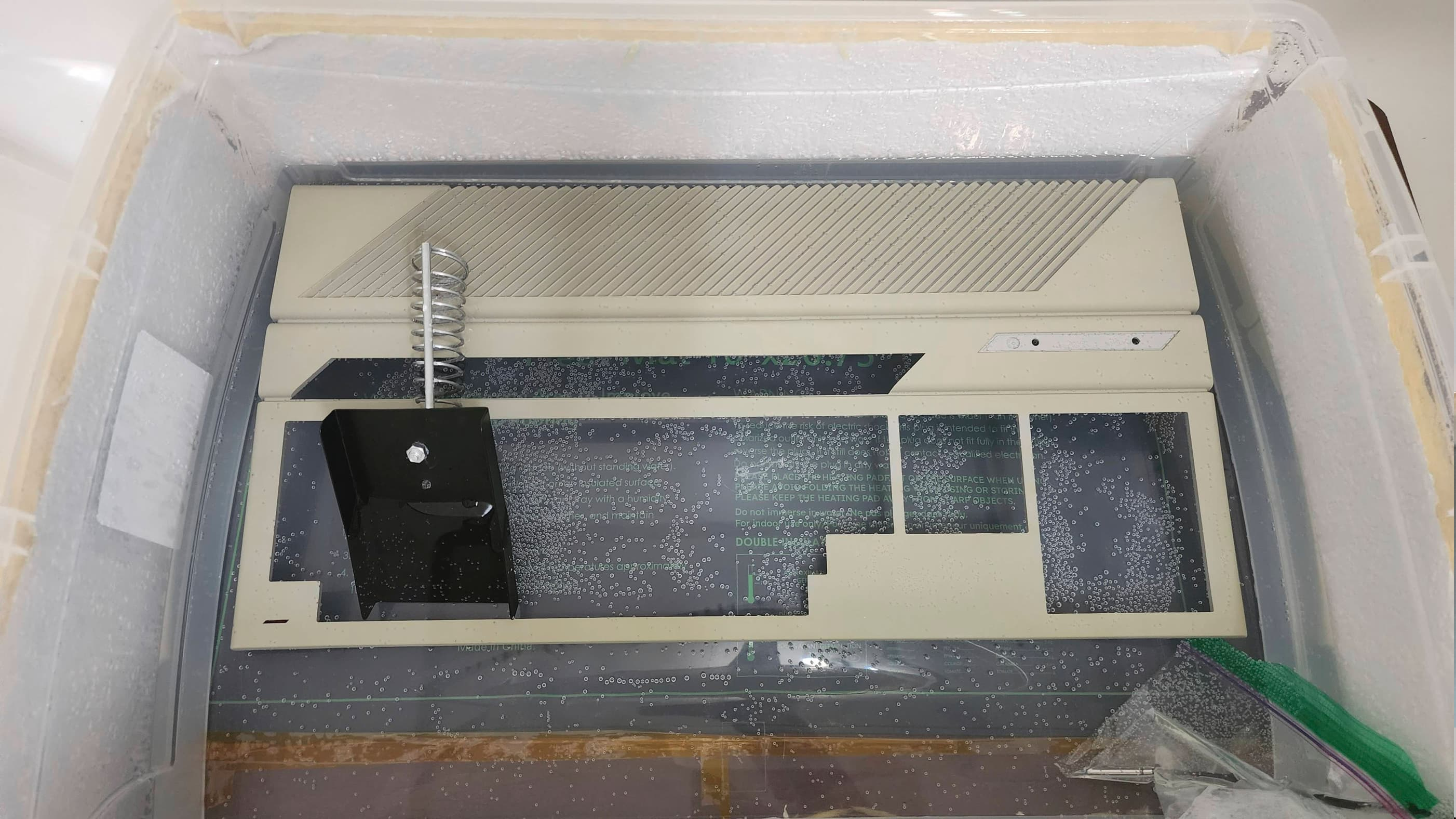
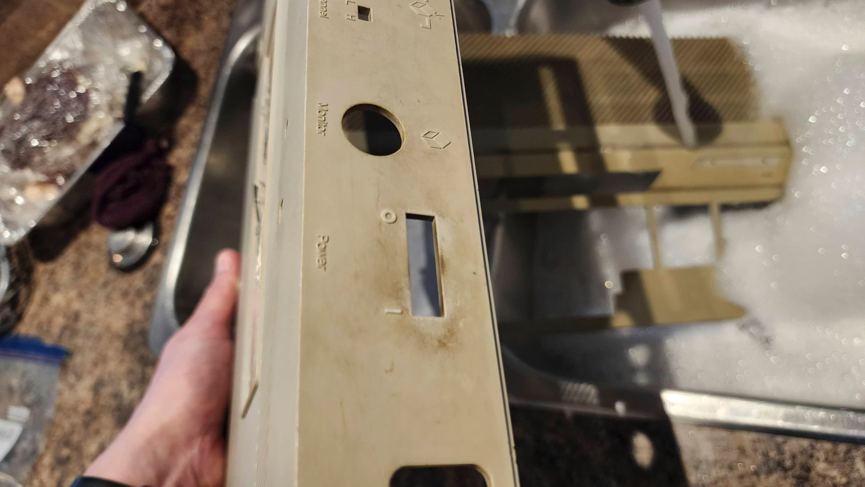
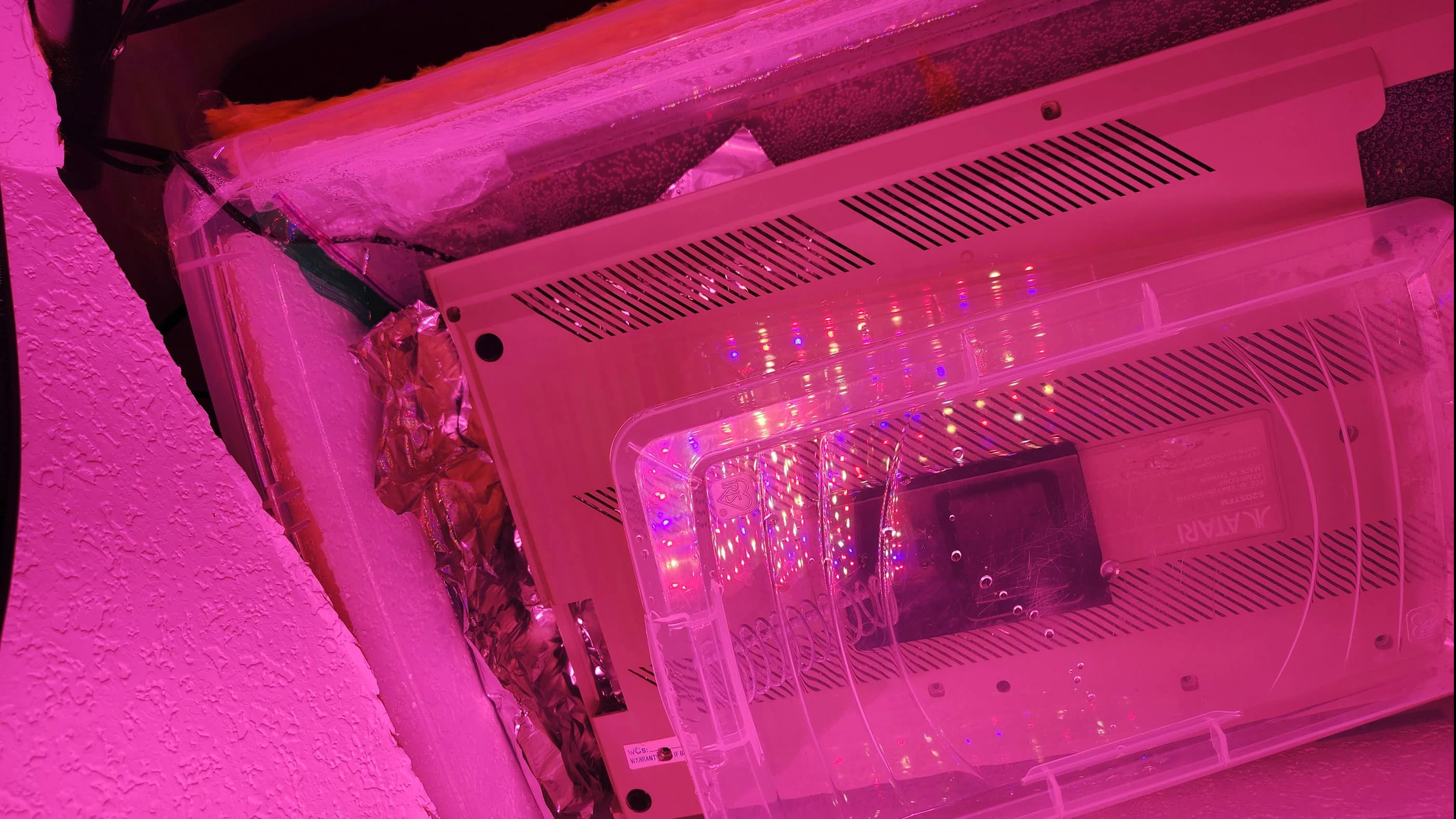
As I only had 3.784l of 9% H2O2 and 2.84l of 6% H2O2, I needed to combine these plus add in 1l of distilled water to cover the case. This combination left me with a ~7.7% H2O2 solution that I then heated to between 26C and 32C using a plant bed heating pad underneath an insulated plastic container. As Hey Birt!’s preferred method is to use a prolonged period of soaking in 6-12% H2O2 with no UV light to avoid blotching, I thought I’d try this.
After 19 hours of soaking in the heated ~7.7% H2O2, the badly yellowed top case had noticeably improved, but it still had a way to go. Being a bit pressed for time, I introduced a full spectrum UV light that was suspended 35.5 cm above the container. I then let it soak for a further six hours under this configuration. The result was quite astounding, with the top case almost completely reverting back to its original colour.
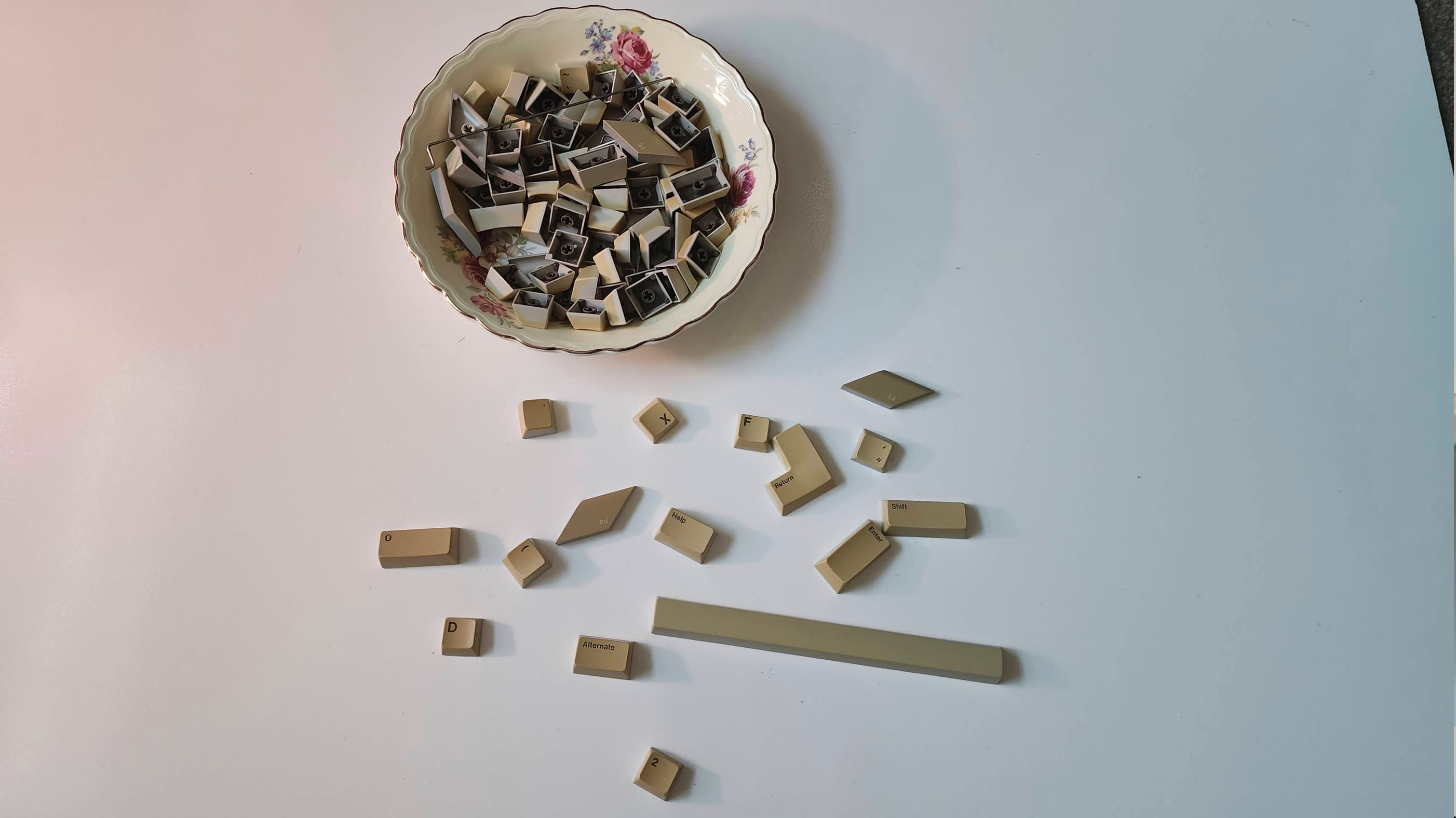
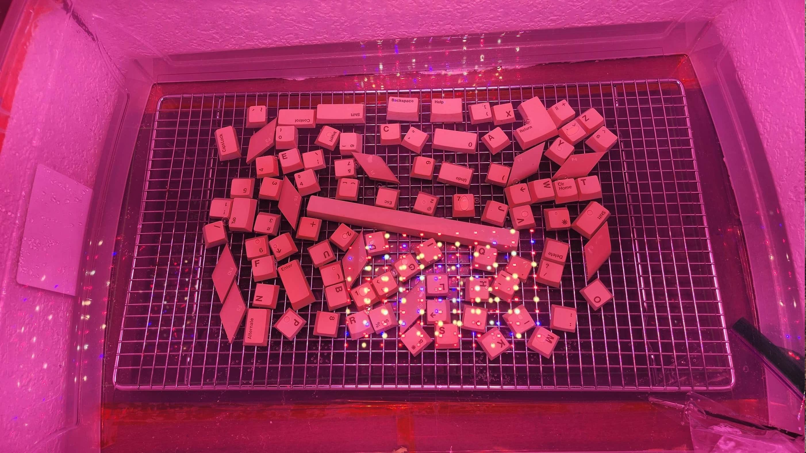
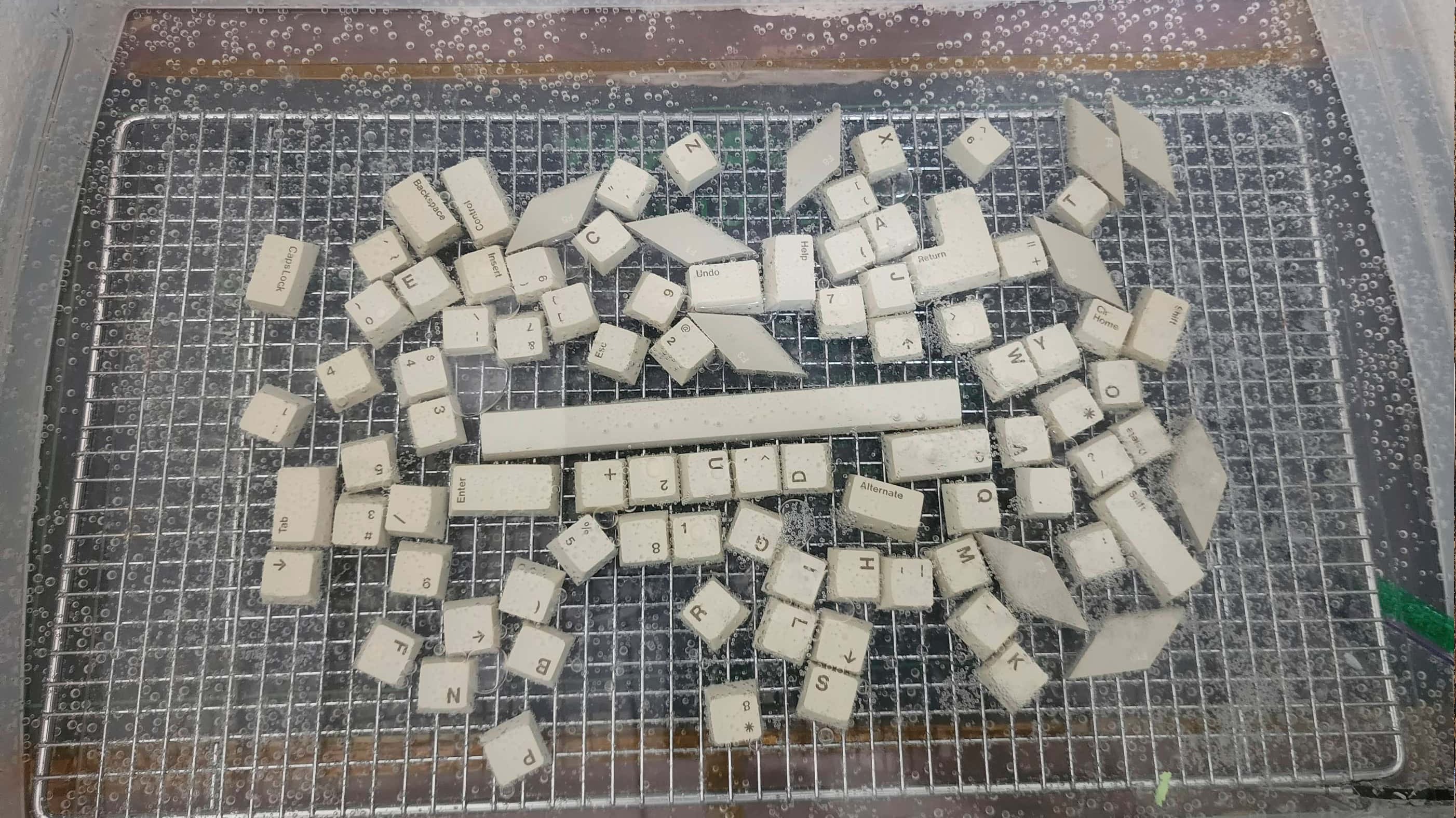
Next up, I tried the same approach for the individual keys, soaking them in the heated H2O2 solution for 14 hours before applying the UV light for another six. To keep the keys upright and facing the UV light, I placed them on a baking rack and then covered them with a thin glass panel from an old picture frame. I then agitated the setup every hour to make sure the bubbles would cause blotching. In the end, the result was also satisfying, though the keys probably needed another couple of hours under the UV light as they still stubbornly held onto the yellow oxidation.
For the bottom case, which wasn’t badly yellowed, I put it straight under the heated ~7.7% H2O2 and UV light for six hours. The result was pretty good, though it did not quite get to the same state as the top case but when put together, it is almost impossible to notice. From all this, I suspect that a higher concentration of H2O2 will expedite the process whether with or without the UV light, but a prolonged soak without the UV definitely produces an even result without blotching.
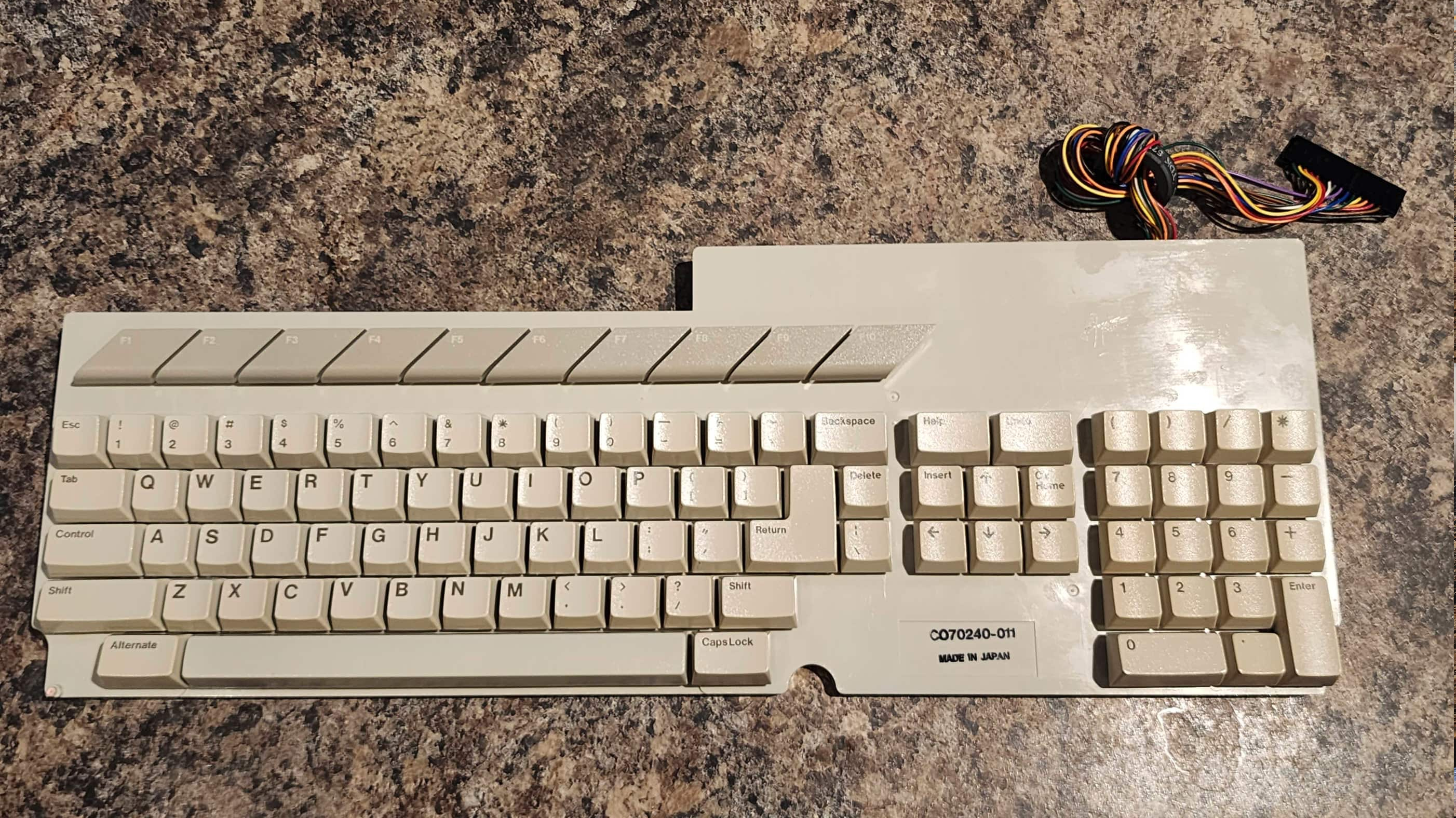
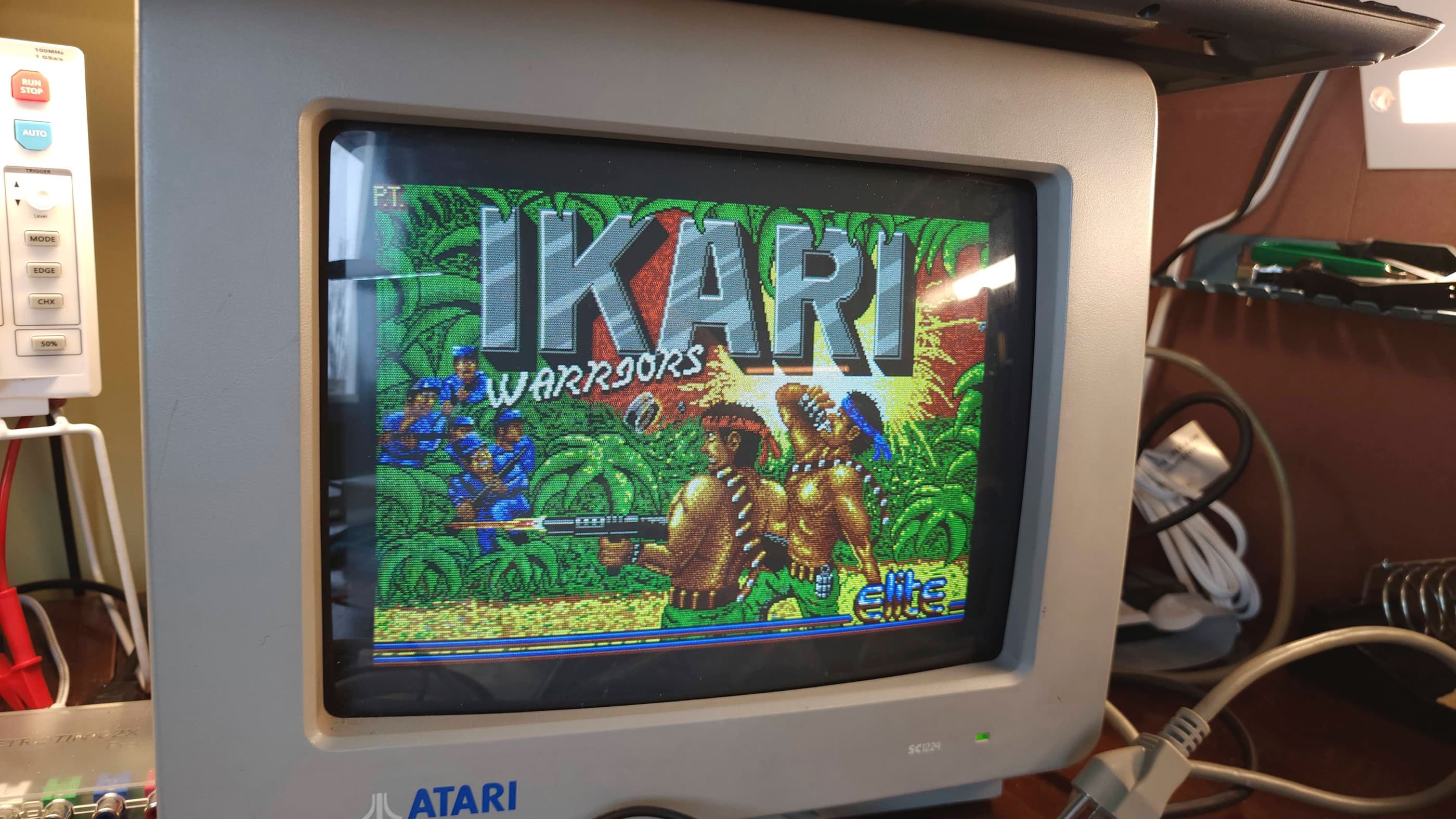
After putting everything back together and purchasing a new mouse off Ebay UK, I spent more time testing the 520 and of course, playing games. I was especially interested in playing the same games that I had for the Amiga and to be honest, I was really impressed with the ST. Other than the noticeably limited sound experience compared to the Amiga, the ST more than held its own. So much so, that I’ve developed an affinity for this computer that’s on par with my love for the Amiga. 🙂
Parts & Products Used: 99% isopropyl alcohol; Chemical Guys Natural Shine; Deoxit D5; electrolytic capacitors (axial): 16v 470μF (1); electrolytic capacitors (radial): 16v 22μF (3); 16v 470 μF (1); 25v 47μF (1); 50v 1μF (2); C025912–38 Memory Management Unit (MMU) (1); Keelog PSU; 8.5l 5.4% H2O2; full spectrum LED grow light; Vivosun Seedling Heat Mat; Atari STM-1 mouse

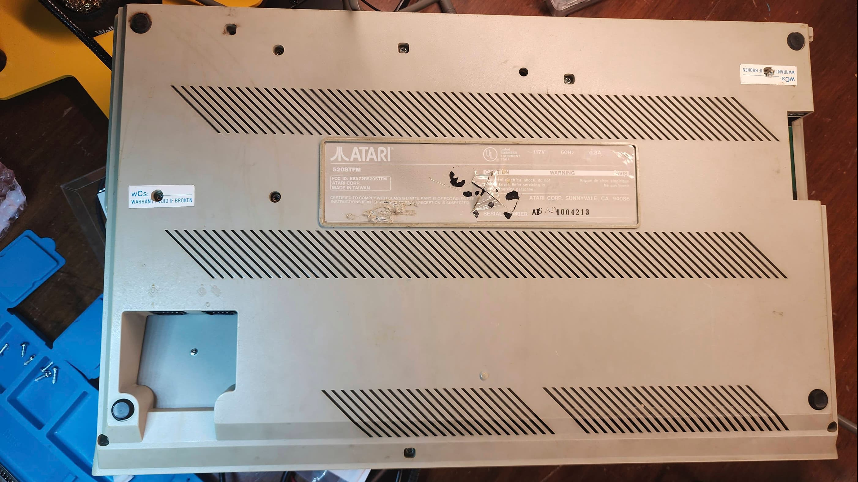
Atari 520 STFM (1MB)
Years (1985-1993)
Interesting Fact: The 520 STFM was a later model version of the 520 STM that included an internal 720k floppy drive; hence, the ‘F’ in the name. (source) It also had an internal power supply and was expandable to 4MB. (source) To see an interesting video on the history of the Atari ST, I’d recommend Peter Leigh’s (aka Nostalgia Nerd), ‘The Atari ST Story’.
Condition When Acquired: Partially Functional
Current Condition: Fully Functional


Project Details: I acquired this unit while I was working on my 520 STM and used the MMU from this STFM to validate my theory that the MMU in the STM was causing the 4-way video display. I knew from the seller, that the STFM booted to the desktop screen but that the internal floppy was non-responsive. So, while I finished the restoration of the STM, I also started in on the STFM.
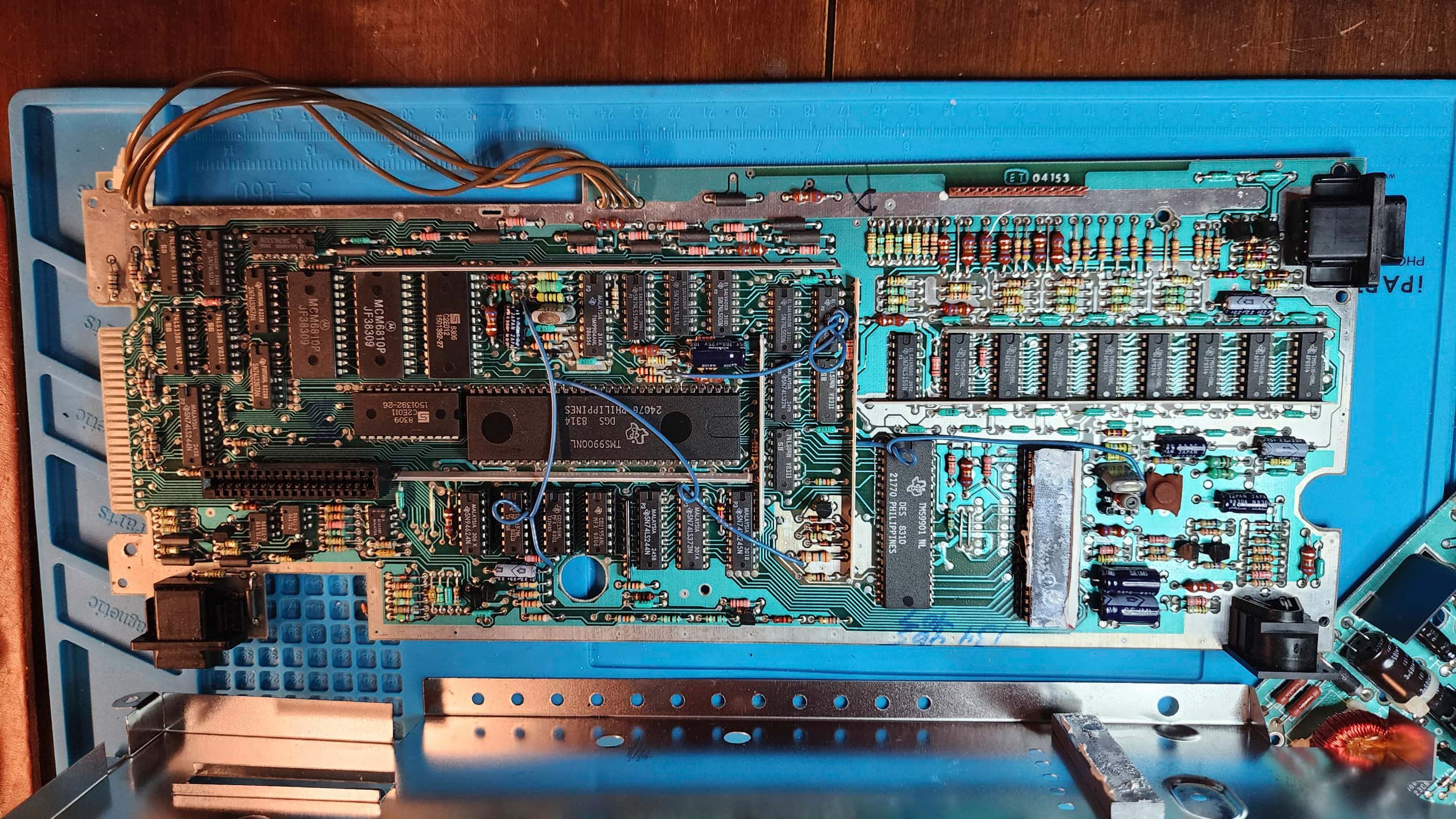
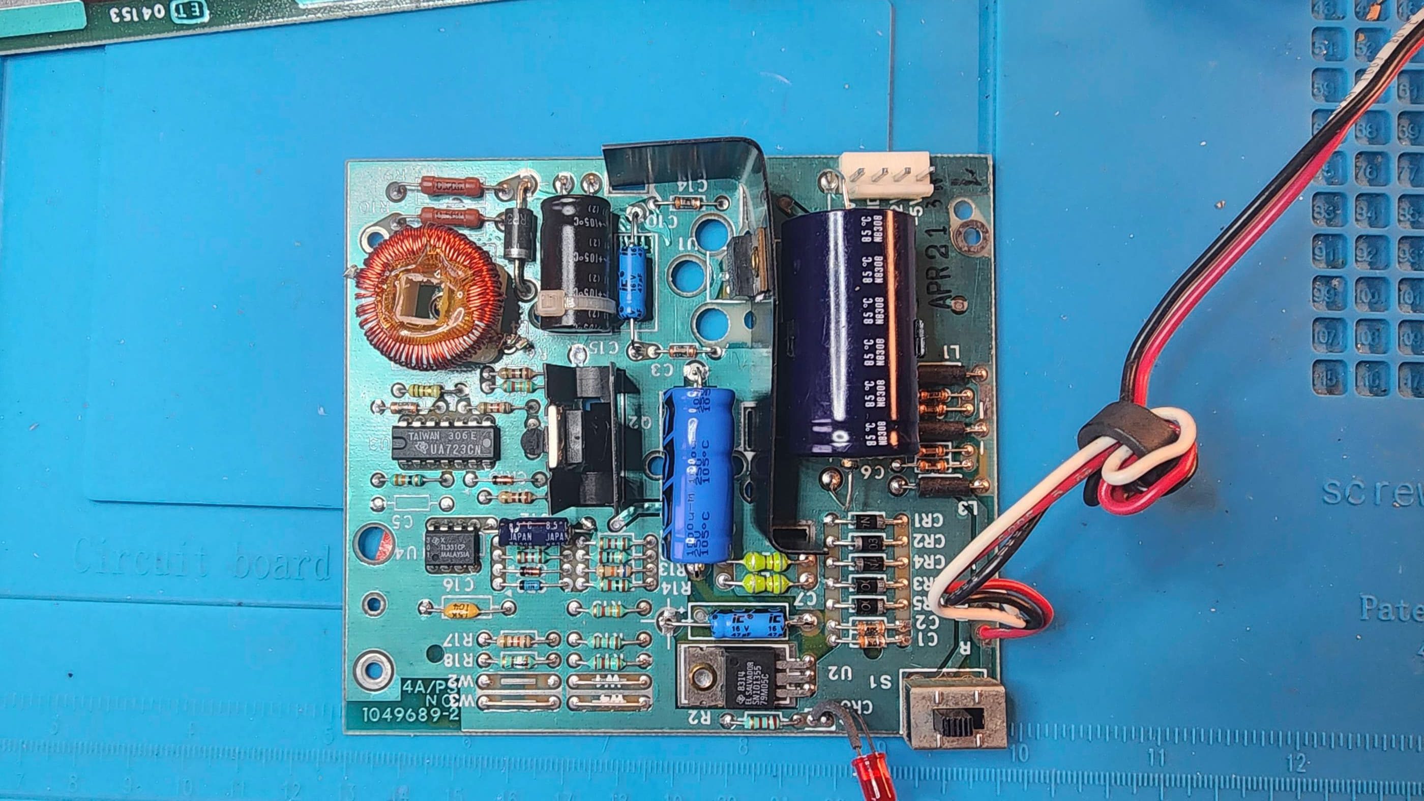
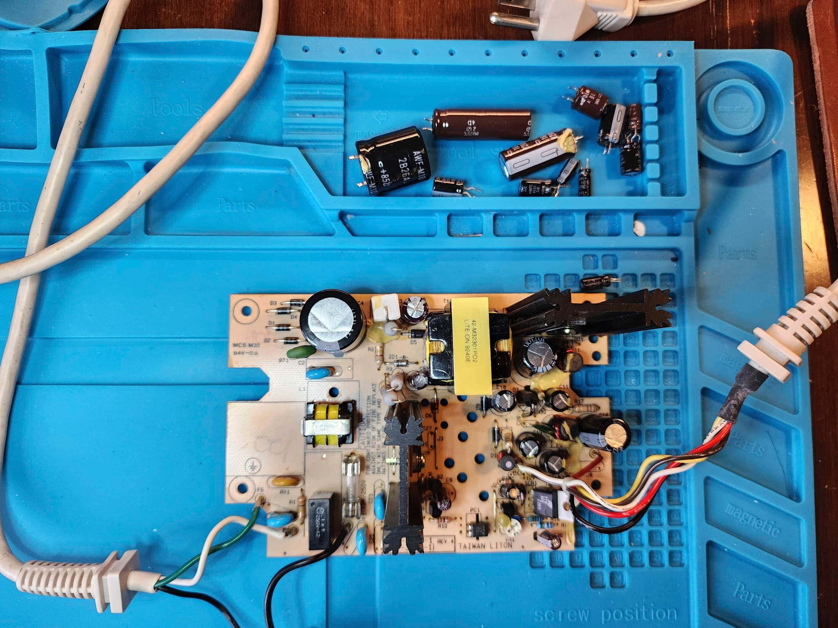
The first two things that I noticed after opening the unit was a bulging cap on the internal PSU, and that at some point in the machine’s life, someone had upgraded it to 1MB by adding another bank of memory (thankfully they socketed these).
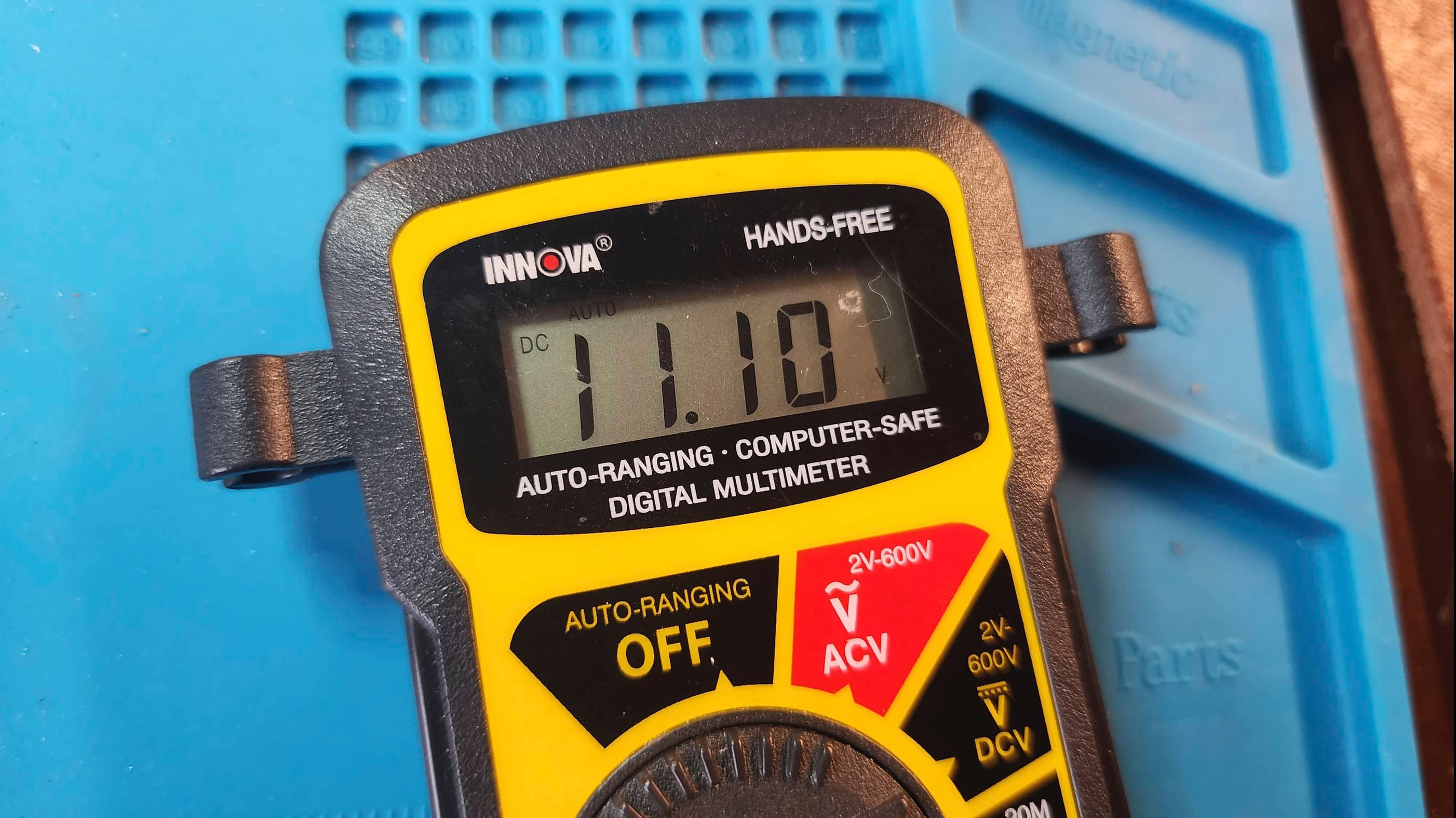
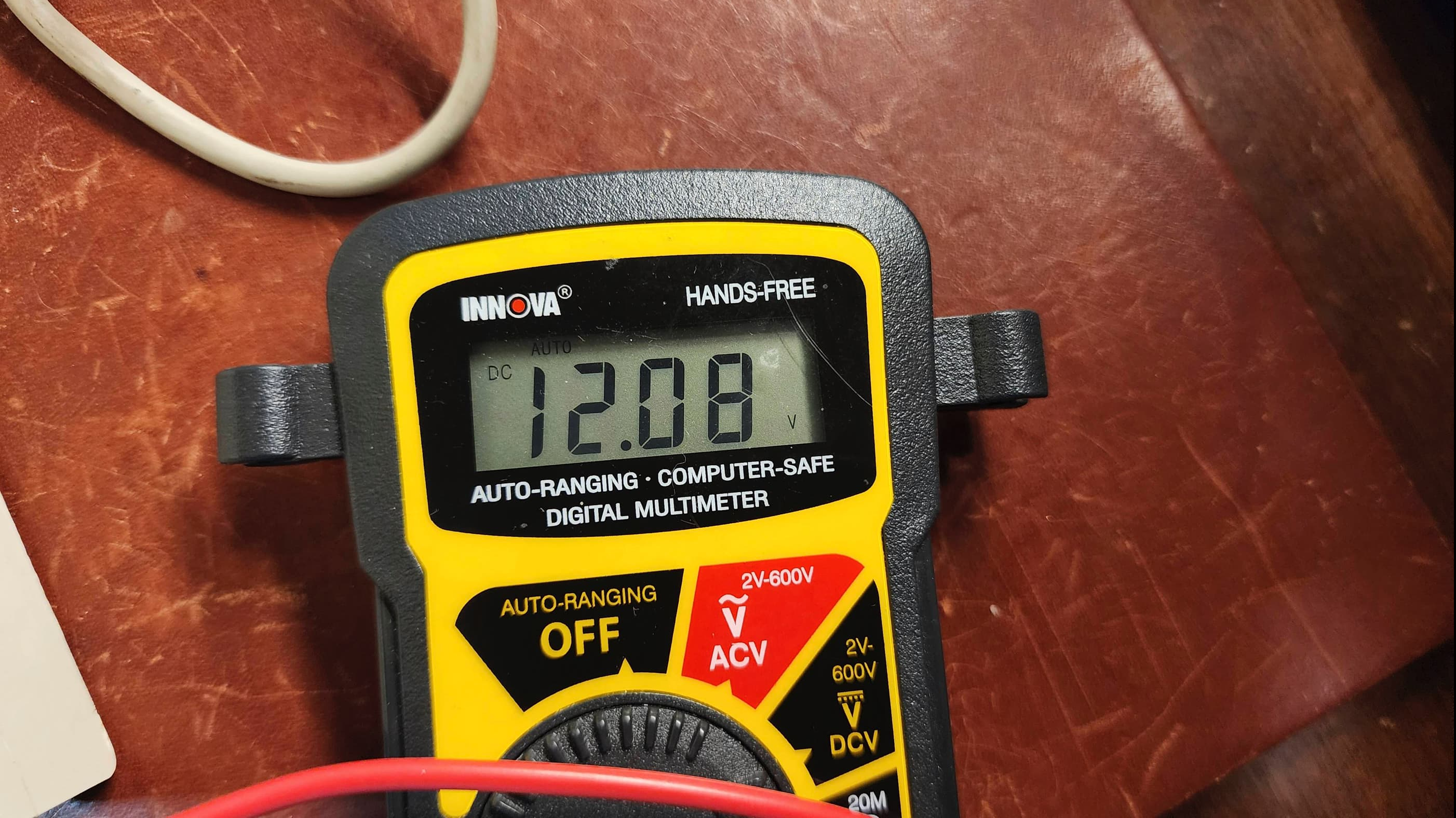
Thinking the drive issue might be a lack of 12v power, I tested the voltages and sure enough, only 11.1v was present. This confirmed to me that my first priority would be to replace the capacitors on the PSU add for good measure, the bridge rectifier.
Once this was done, I tested the unit and confirmed that I was now receiving an output of 12.1v along with the proper 5v. However, the drive still was not functional. Having an extra ST drive that I knew was working, I tried that one as well and… crickets. Nothing.
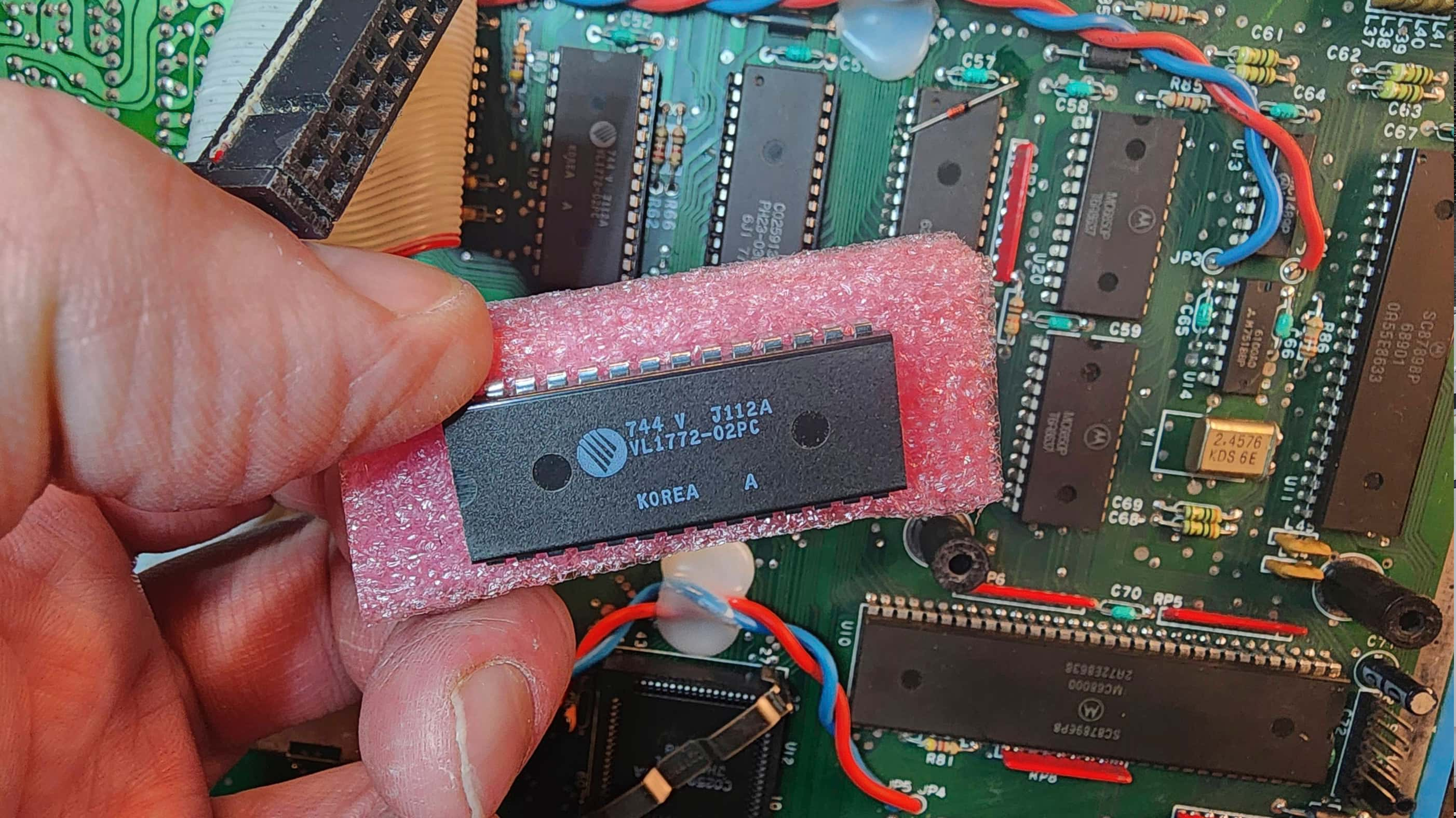
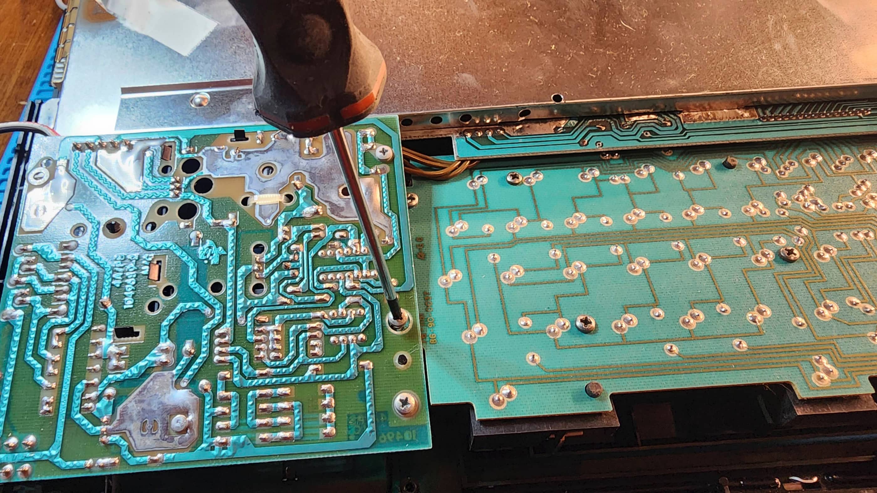
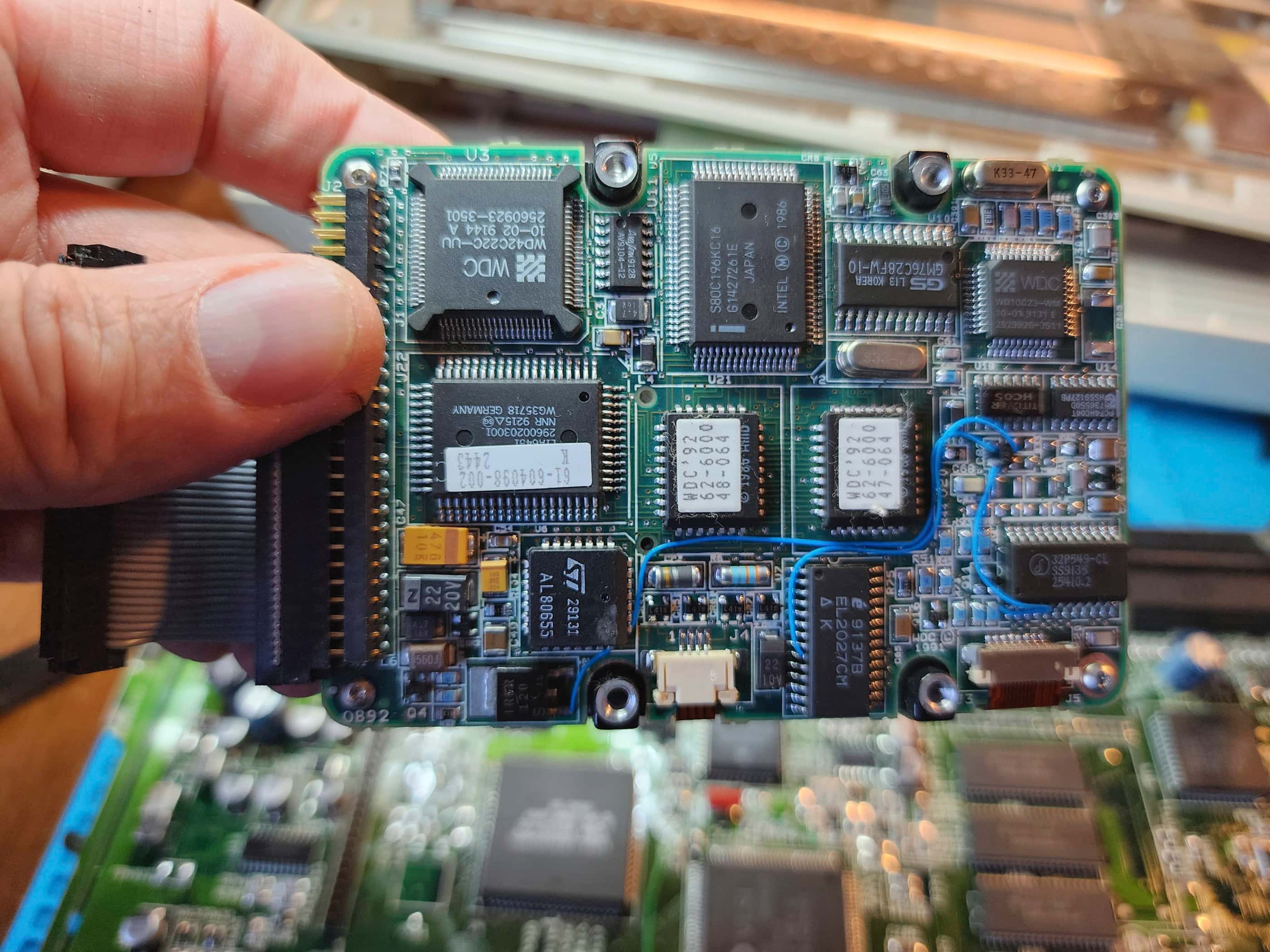
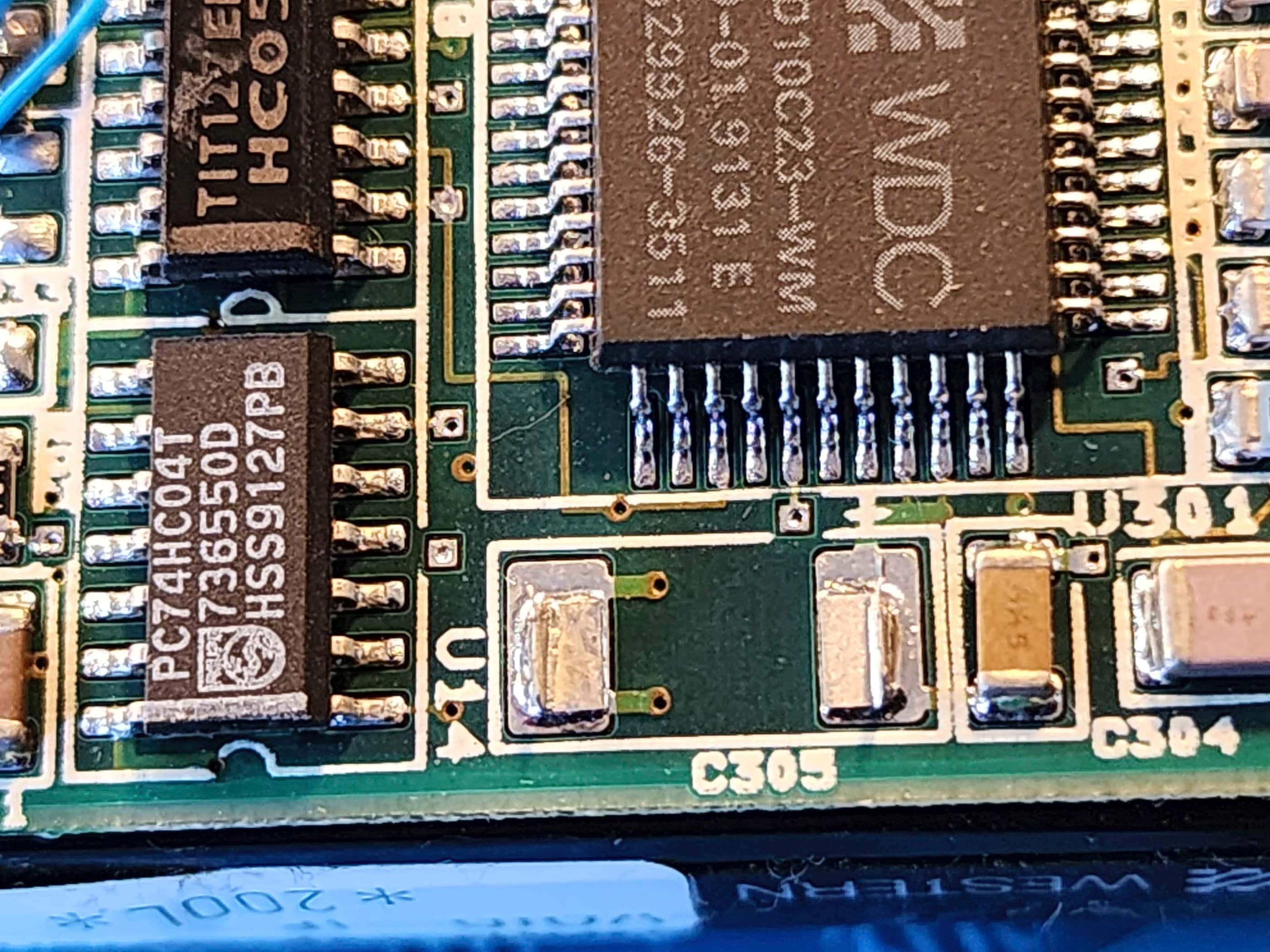
This prompted me into following the diagnostic steps laid out in the handy Atari ST Service Manual. This included the use of the diagnostic cartridge and a logic probe. What I discovered, was the Western Digital floppy disk controller (VL1772) had gone bad. As both my 520 STM and my 1040 STF have non-socketed 1772 chips, I couldn’t perform a swap test to confirm, but I could follow the same diagnostic procedures on those units and based on these outcomes, I was pretty confident it was the issue.
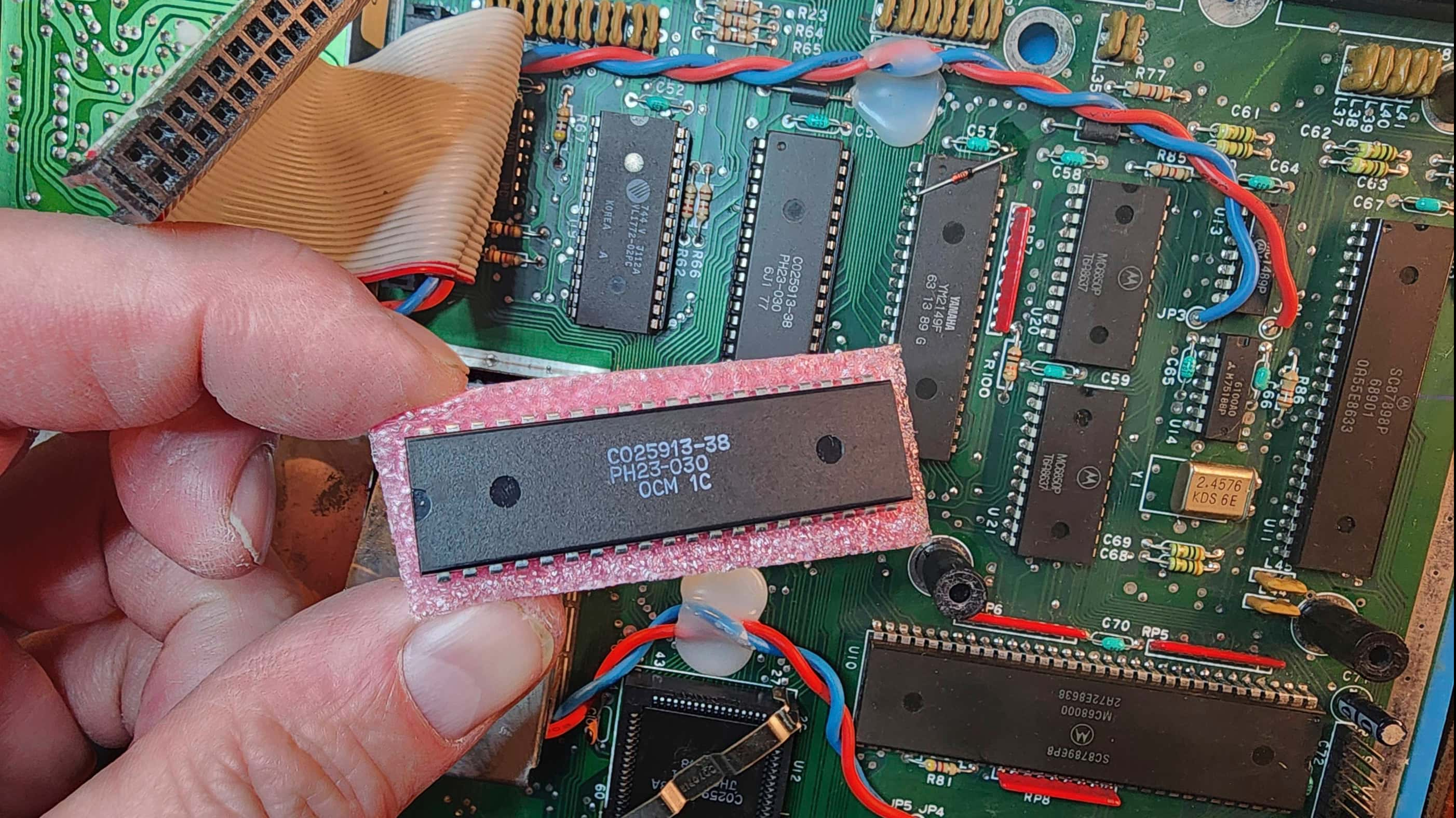
When placing my order with Best Electronics, I also purchased a new DMA chip (CO25913) just to be safe. While I waited for these to arrive, I started in on cleaning the unit and preparing the top case for retrobrighting.
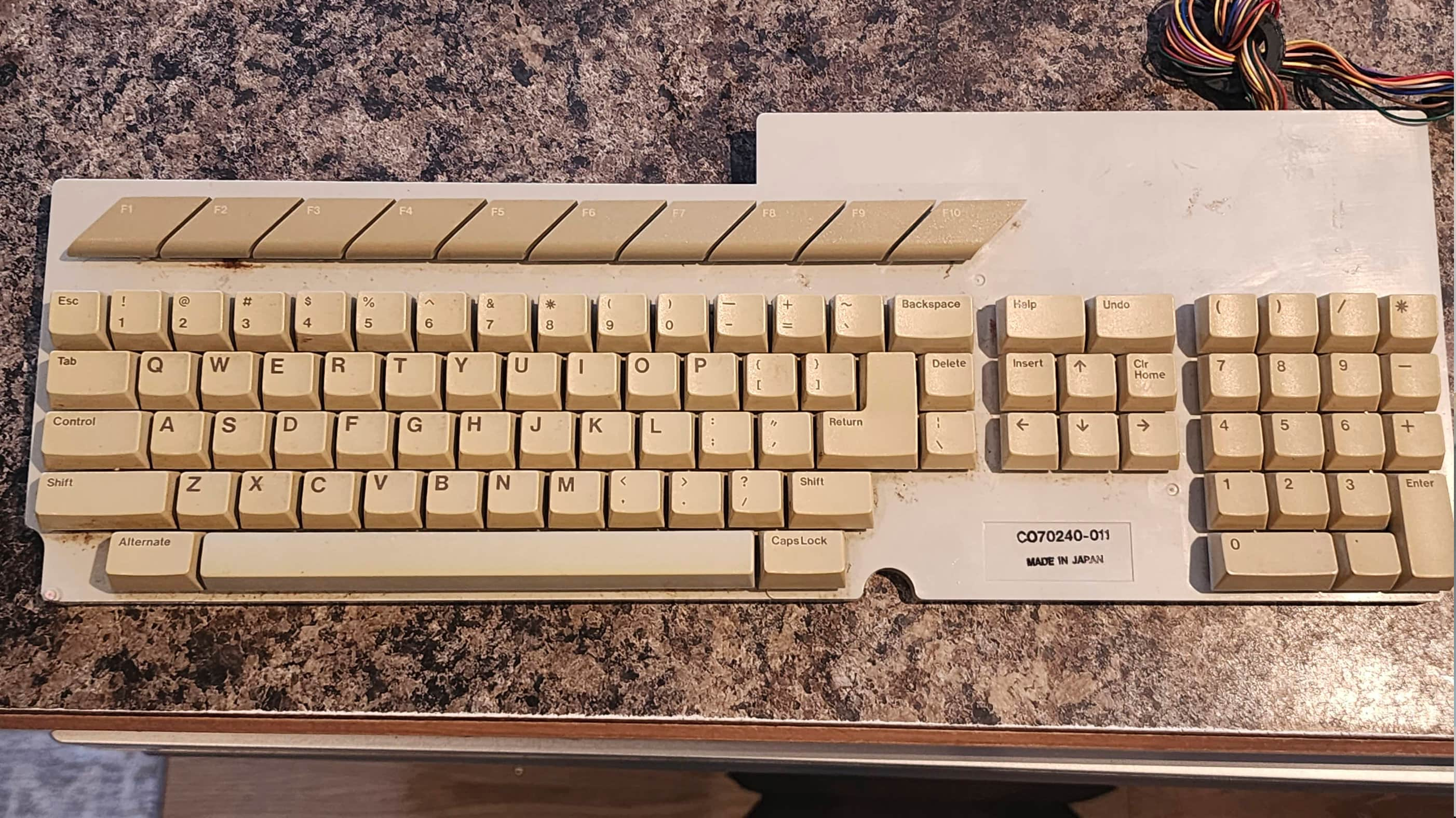
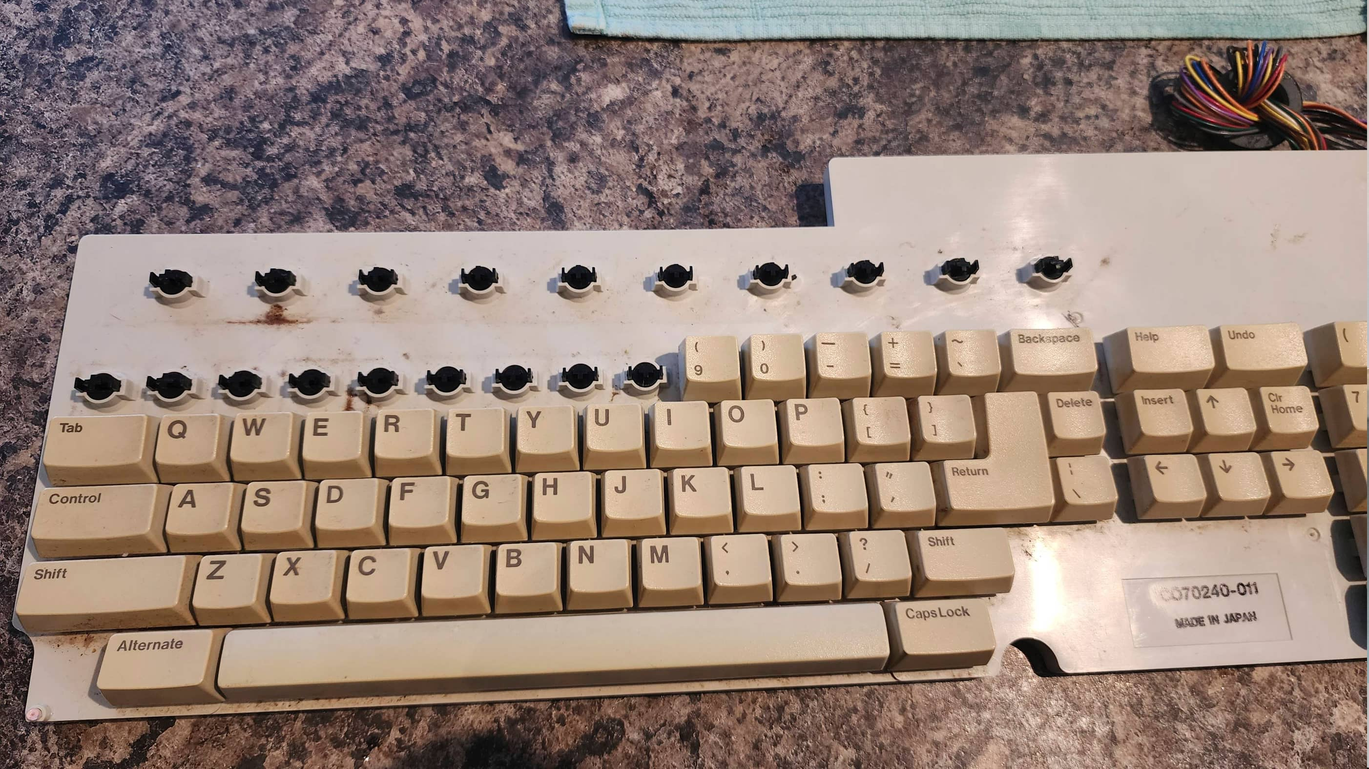
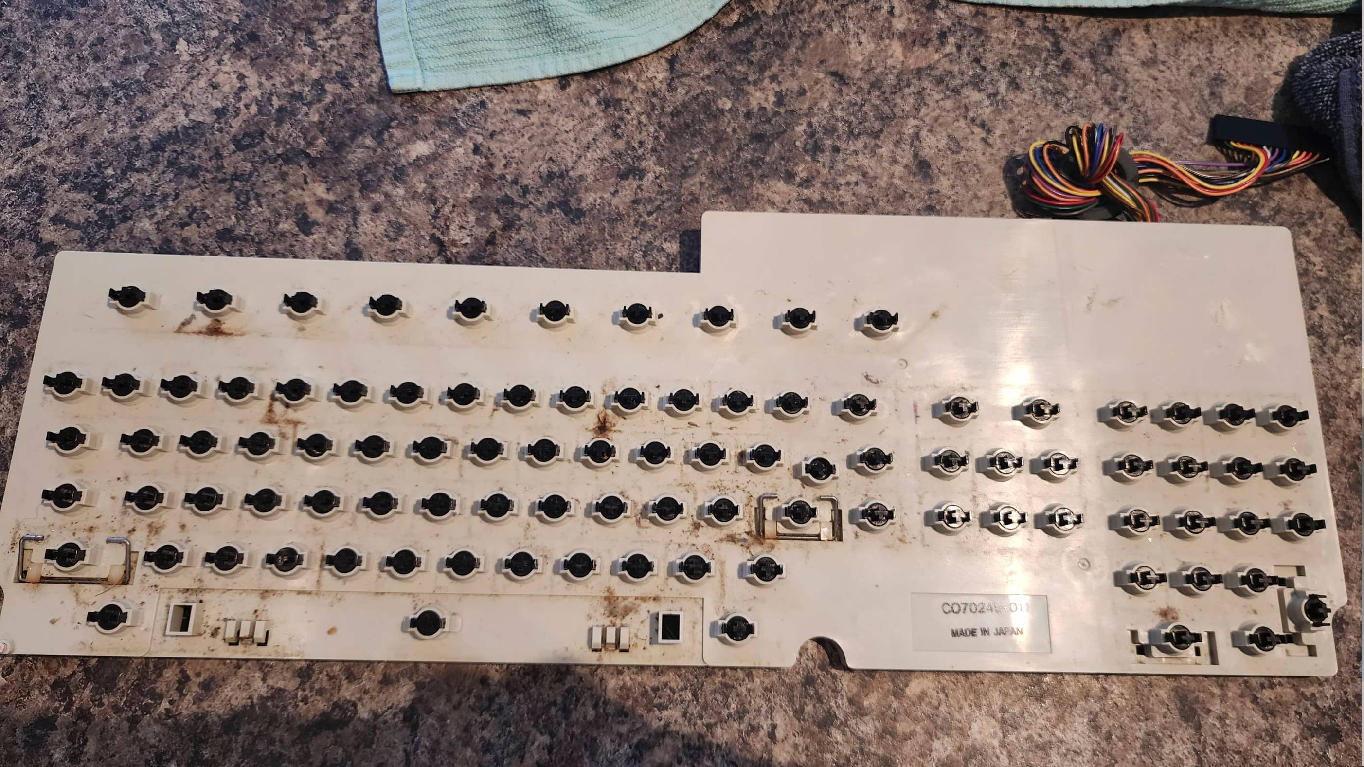
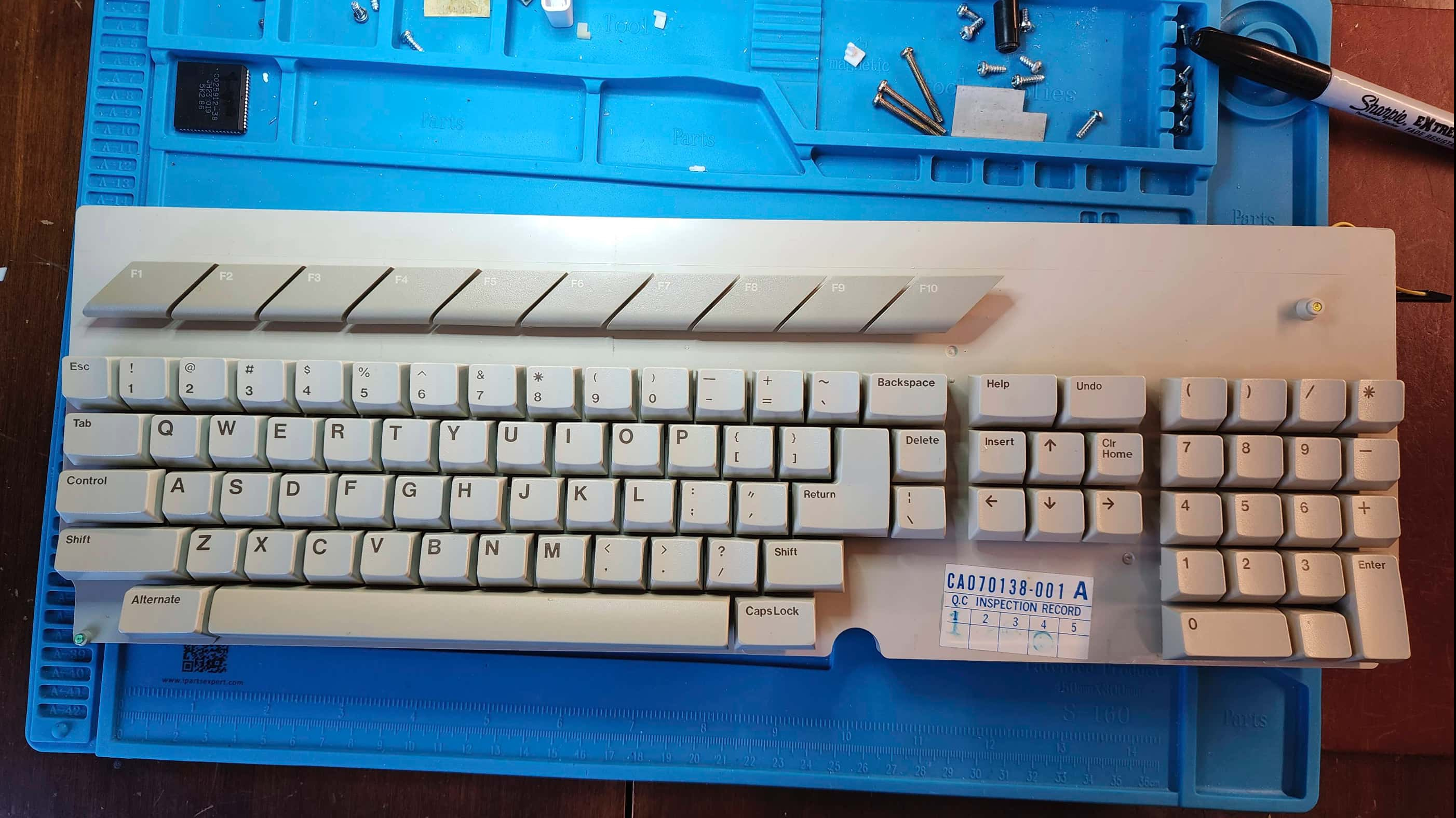
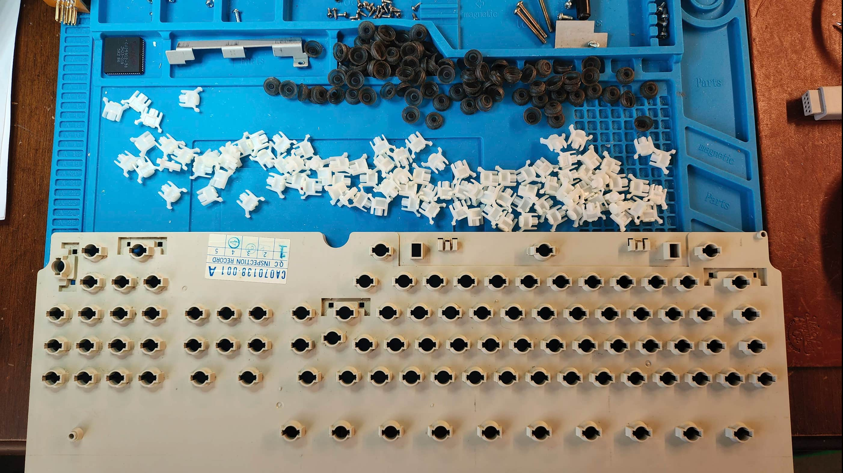
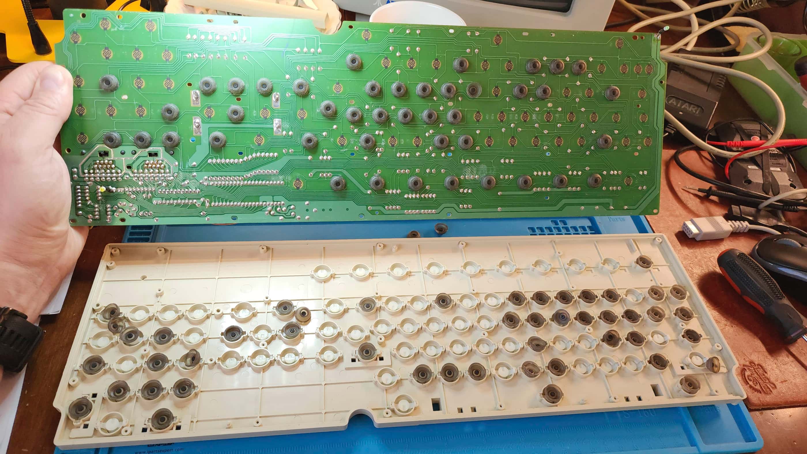
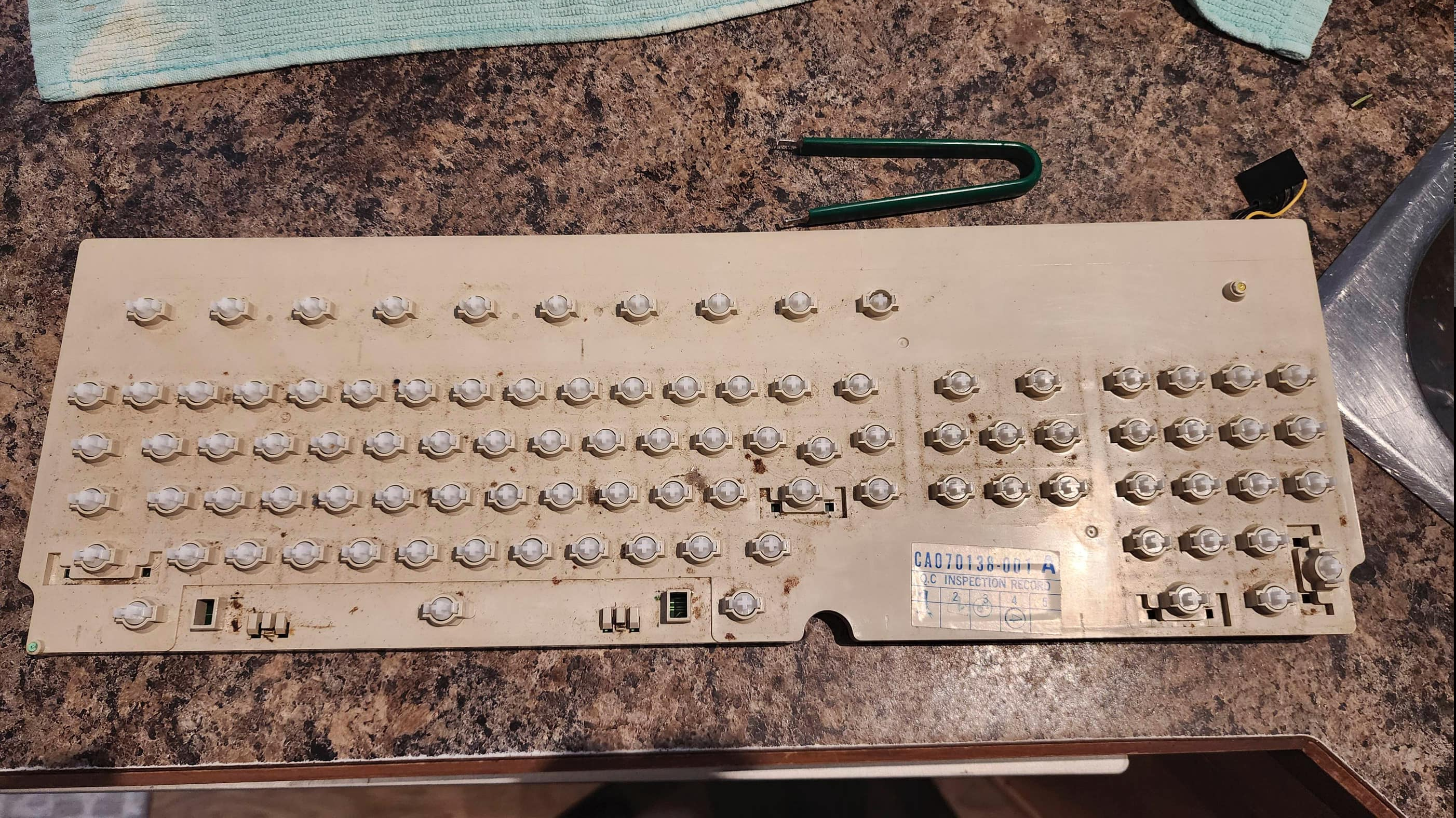
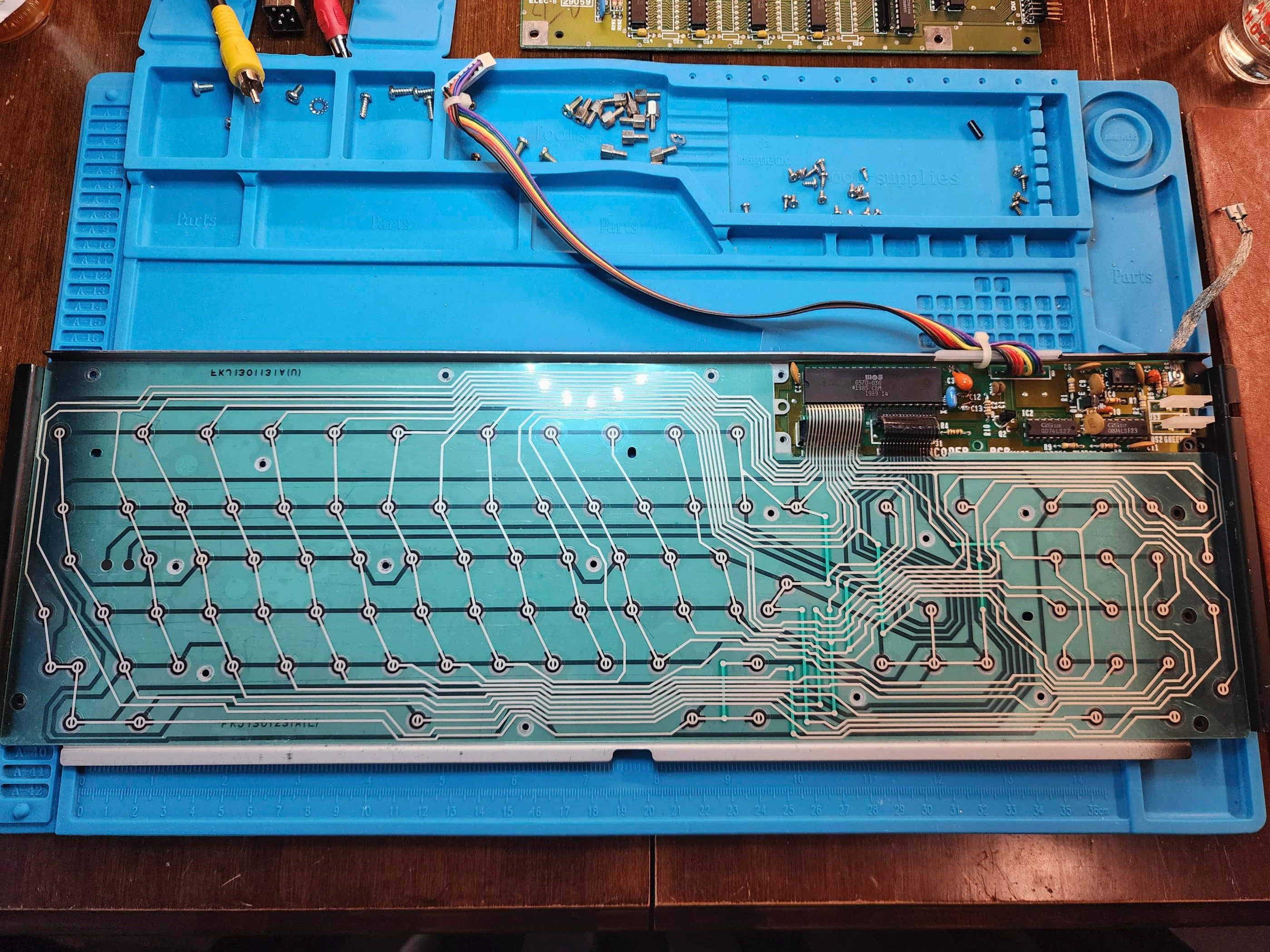
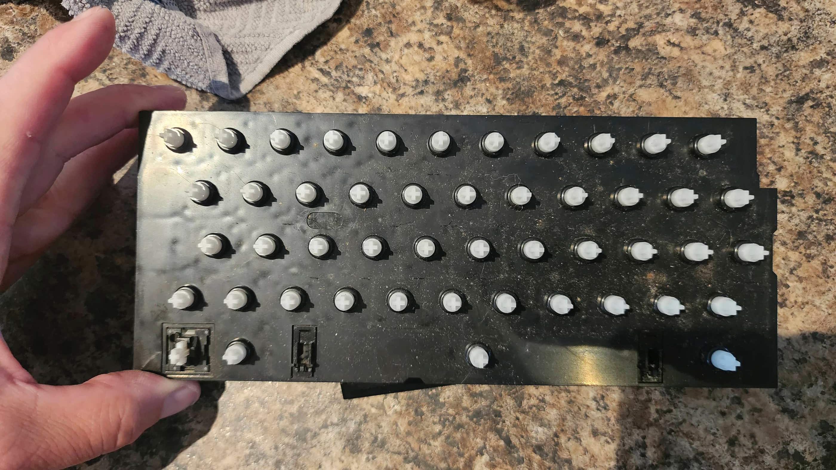
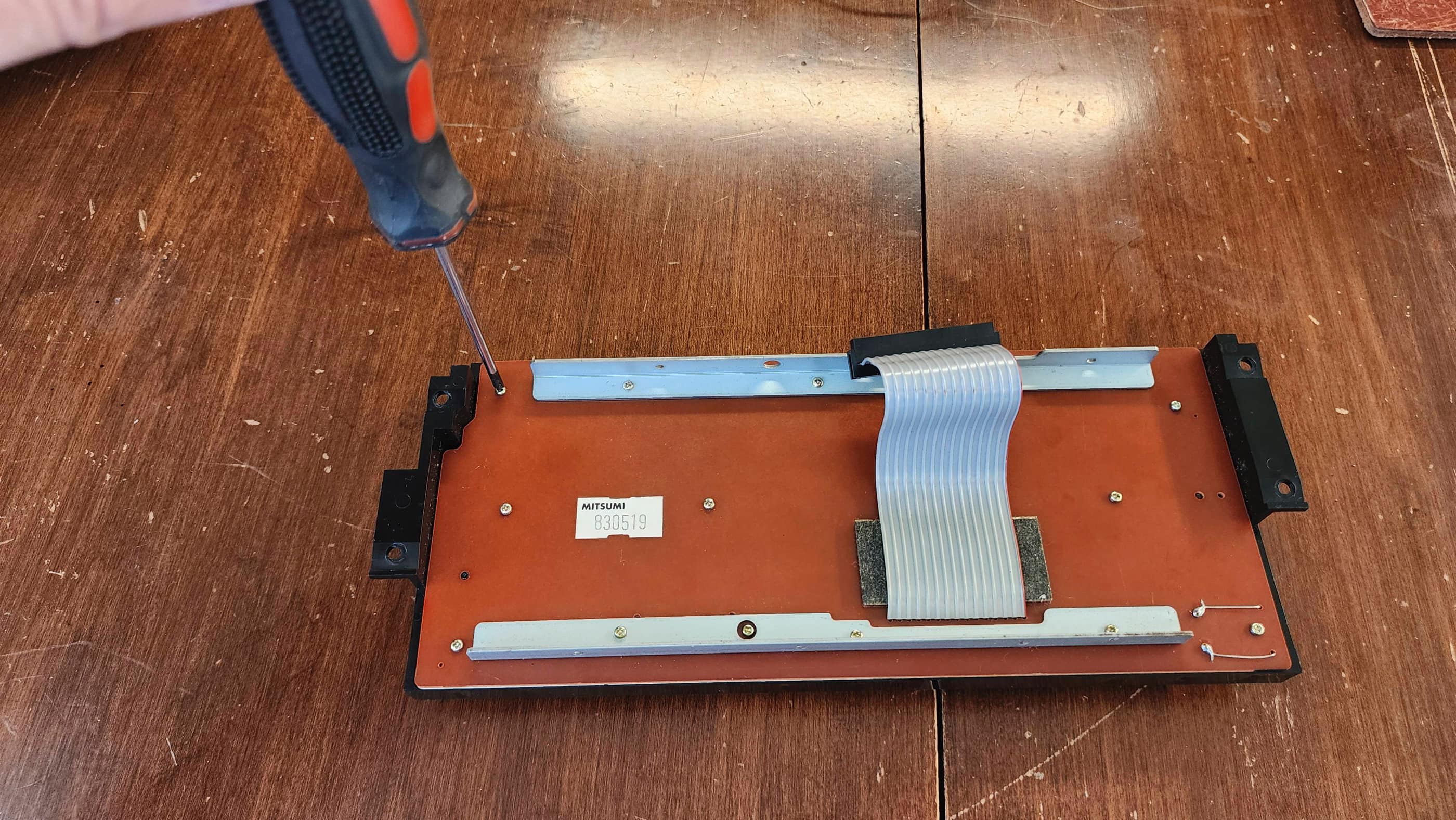
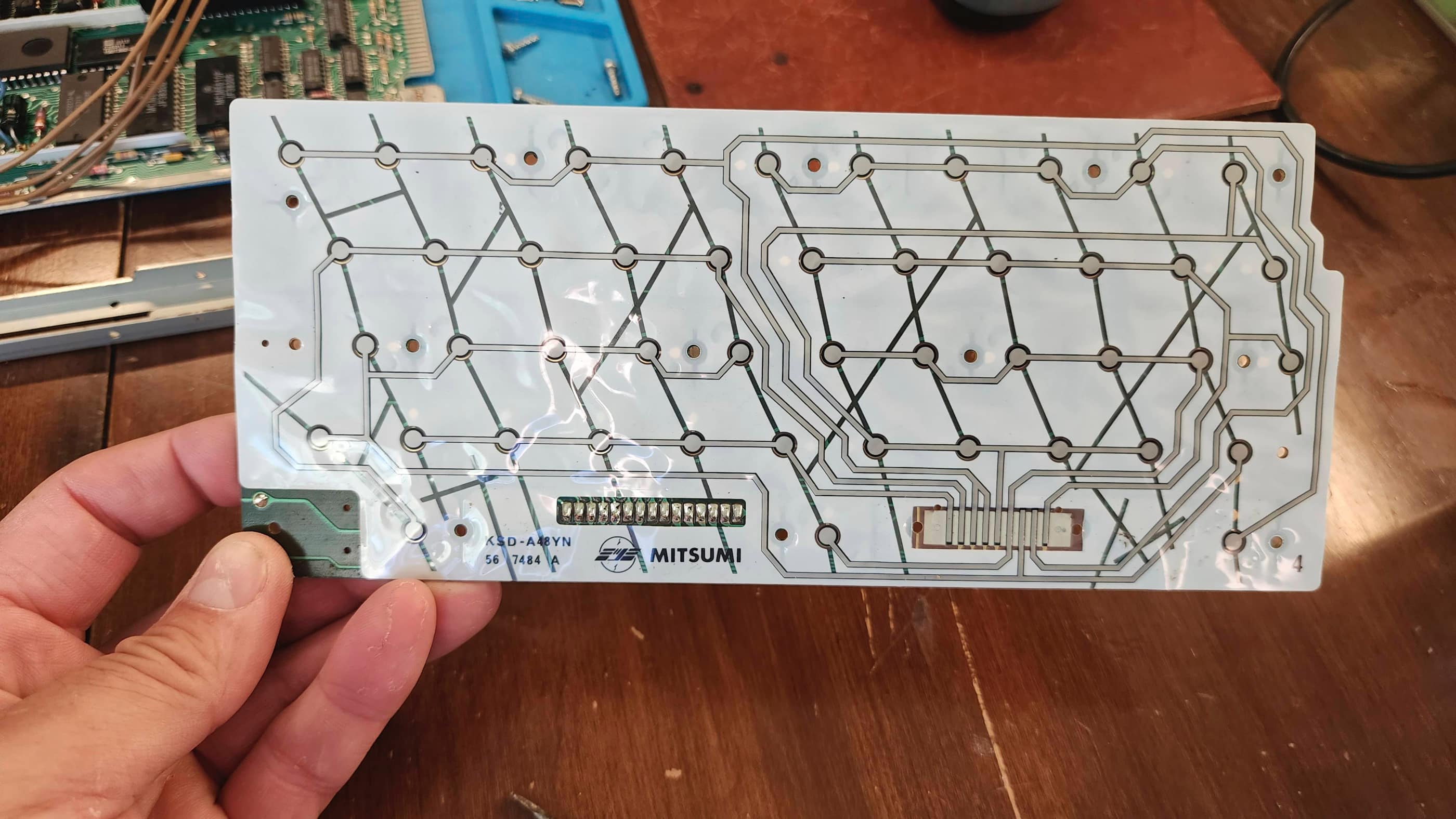
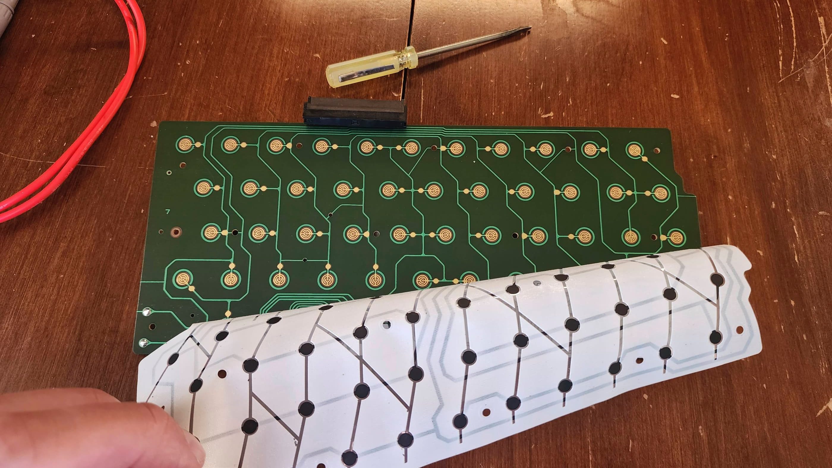
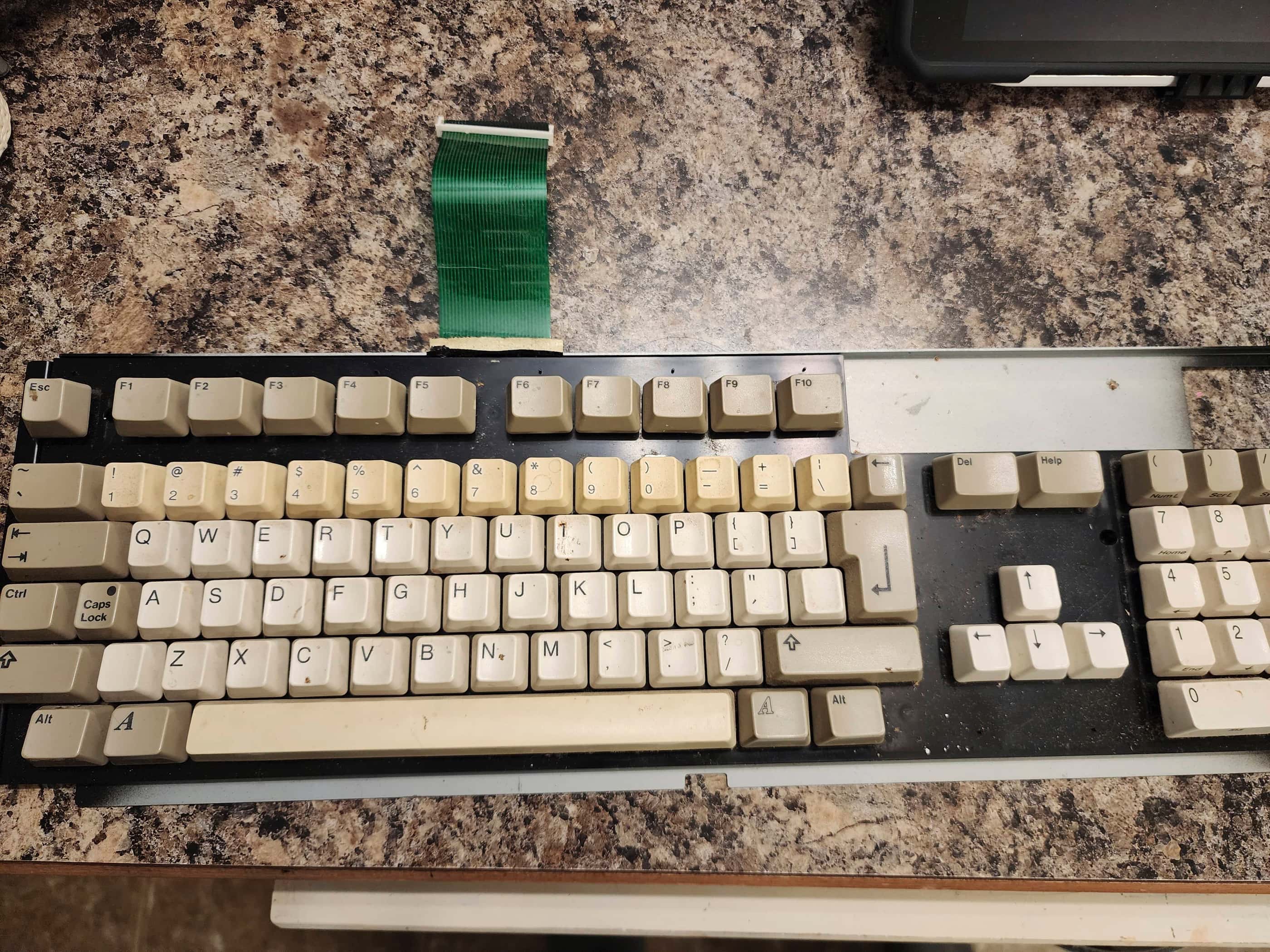
The unit itself was very dirty and had been well-used in its lifetime. While prepping for cleaning, I also discovered that the F10 key was non-functional and once the keyboard was disassembled, I noticed that it was missing its silicone contact. Of course I discovered this after I had placed my order with Best, so I wasn’t going to pay the big shipping costs for a new bag of contacts – maybe I’ll include it in a future order….
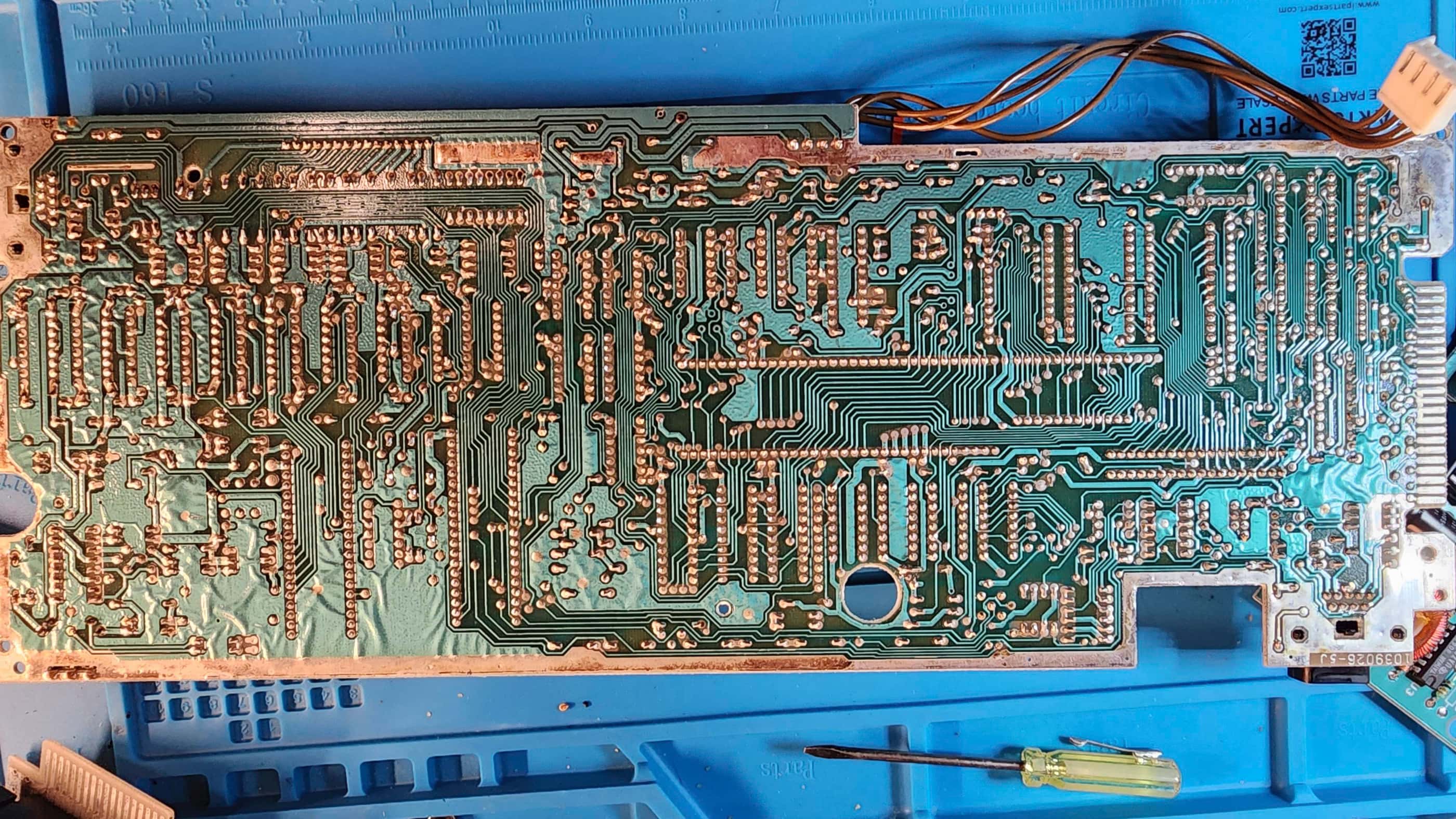
I also spent a long time cleaning the board and removing and reseating all of the socketed chips and treating with Deoxit D5. I also decided that once I got the floppy drive working again, I would substitute it with an internal Gotek, so I ordered a locally printed 3D internal Gotek ST mount and set about mating it with a new Gotek.
I then retrobrighted the top case but unlike the 520STM, the keyboard keys weren’t as yellowed, so I left them. I also reassembled the keyboard, but had to leave the F10 key as I didn’t have a replacement silicone contact.
Finally, the chips arrived from Best and I was very pleased to see that I was right, and that it was the 1772 drive controller. However, for good measure, I also replaced the DMA chip. I then proceeded to test everything with a floppy drive and then the Gotek, and no issues popped up. Before reassembling, I put some recycled heatsinks on the 1772 chip and on the video shifter. I then ran it through more diagnostic testing. I then paired it with a spare STM-1 mouse that I had.
Once back together, I spent lots of time playing games. 🙂
Parts & Products Used: 99% isopropyl alcohol; Chemical Guys Natural Shine; Deoxit D5; PSU electrolytic capacitors (radial): 10v 2200μF (2); 10v 1000μF (1); 16v 1000μF (1); 16v 2200 μF (1); 50v 1μF (2); 200v 220μF (1); 1 Phase 400v 1.5A Bridge Rectifier (1); WD VL1772 chip (1); CO25913 DMA chip (1); Gotek Drive (1); Atari ST internal Gotek 3D printed mount (1); Floppy drive power cable extension (1); 5.4% H2O2; full spectrum LED grow light; Vivosun Seedling Heat Mat;
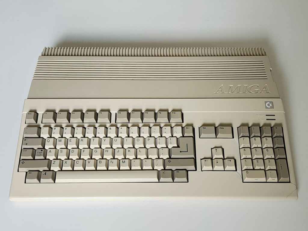
Commodore Amiga 500
Years (1987-1992)
Interesting Fact: The A500 was and still is, my favorite out of all the consoles and computers that I’ve owned. Of course, a big chunk of this is my own sense of nostalgia, but at the time, it really was revolutionary when it came to the combination of graphics, sound, and gameplay.
The A500 was the “low end successor to the Amiga 1000” that was deliberately priced for the consumer market with the goal of making it as successful as the C64. (source) Code named, Rock Lobster, and announced in conjunction with the more advanced A2000, the A500 was a 16 bit, 512K (expandable with a 9.5MB maximum) system built around the Motorola 68000 @ 7.16 MHz NTSC (7.09 PAL). (source)
The lead engineers on the A500 were George Robbins and Bob Welland, who were able to expand the RAM on the original Agnes chip in the A1000, into a 1MB ‘Fat Agnes’ chip. This greatly expanded the A500s graphic capabilities while maintaining a high level of backwards compatibility with existing software. It did however, ultimately slow the machine down. (source)
The A500 became the best-selling Amiga and together with its Amiga siblings, has been credited with revolutionizing the world of creative computing. (source)
Condition When Acquired: Partially Functional
Current Condition: Fully Functional


Project Details: Reunited at last! I finally found what I consider to be the best computer that I’ve ever owned: an Amiga 500. I bought my first A500 back in 1988 and it served me well all the way through my undergraduate days at university. In fact, my wife also had an A500 at the same time, so when we met in university, I knew we were meant to be.
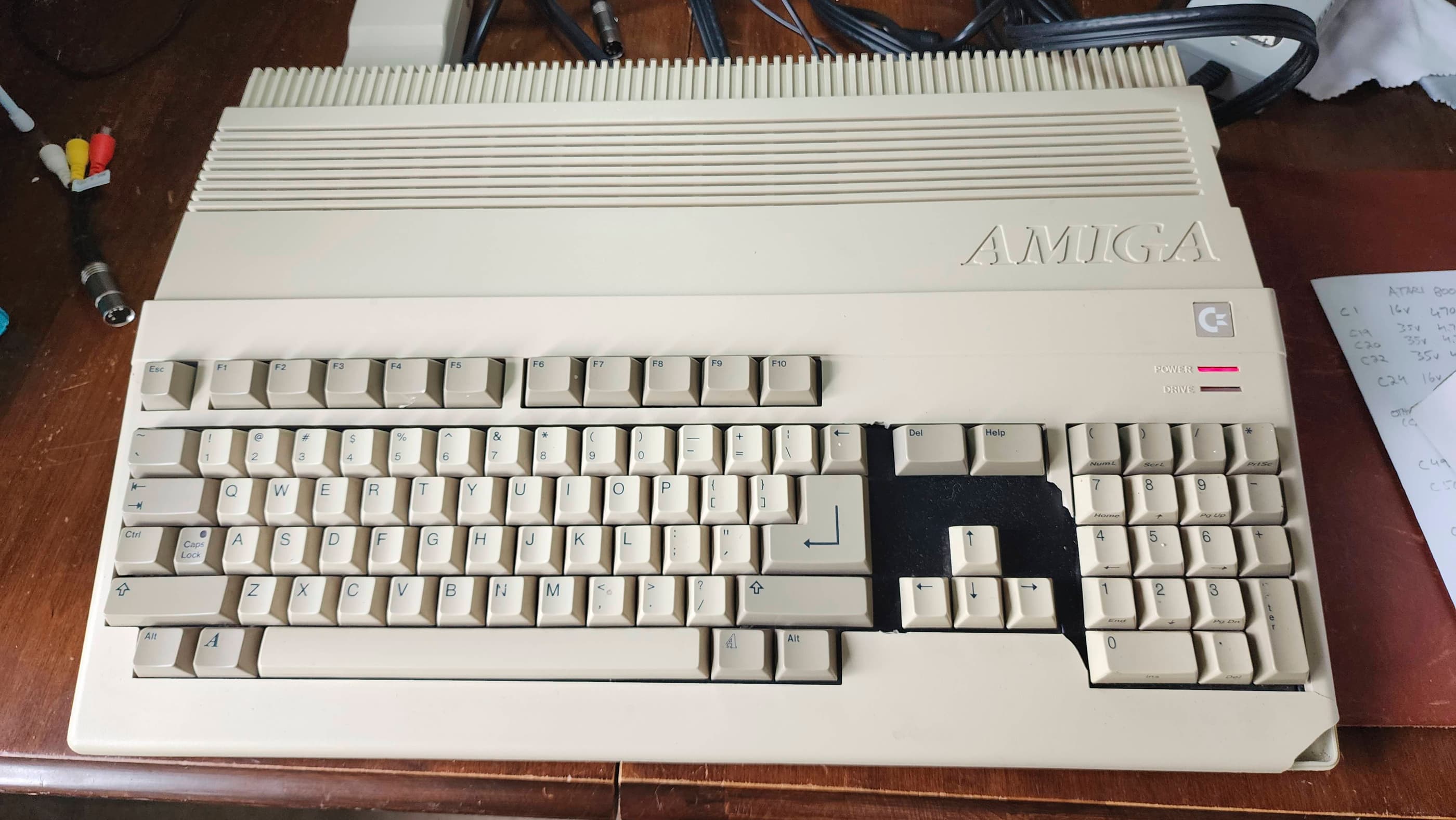
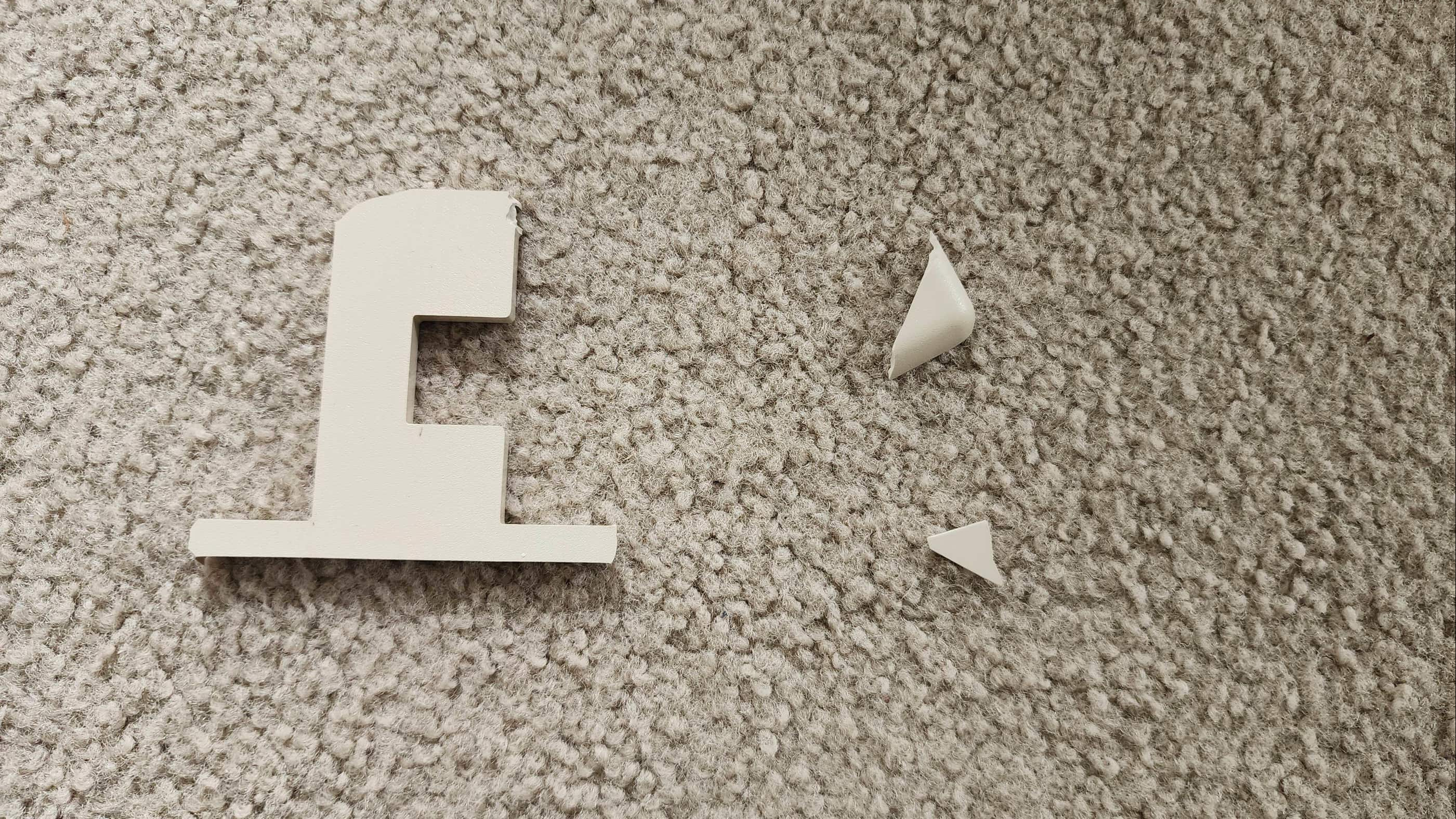
This system came to me from a retired collector who was downsizing his collection. It had been in storage for a couple decades and had last been tested six years ago. Unfortunately, it didn’t survive shipping very well and arrived with the case broken in several locations. Using Permatex Plastic Welder epoxy, I was able to adequately fix the damage; however, I will look to replace the entire case someday. Also, as I knew that it was missing its side expansion port cover and that the bottom expansion port cover was broken, I ordered in replacements in advance of receiving the computer.
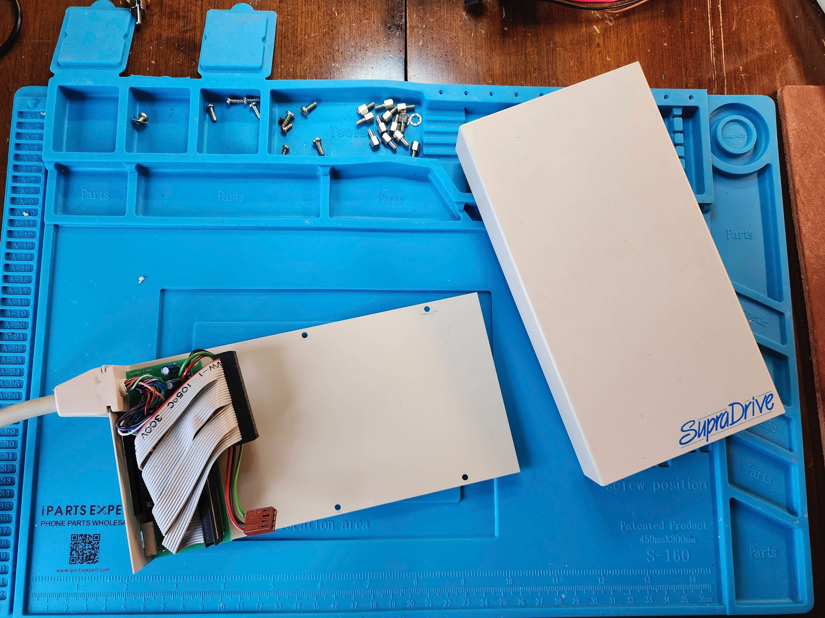
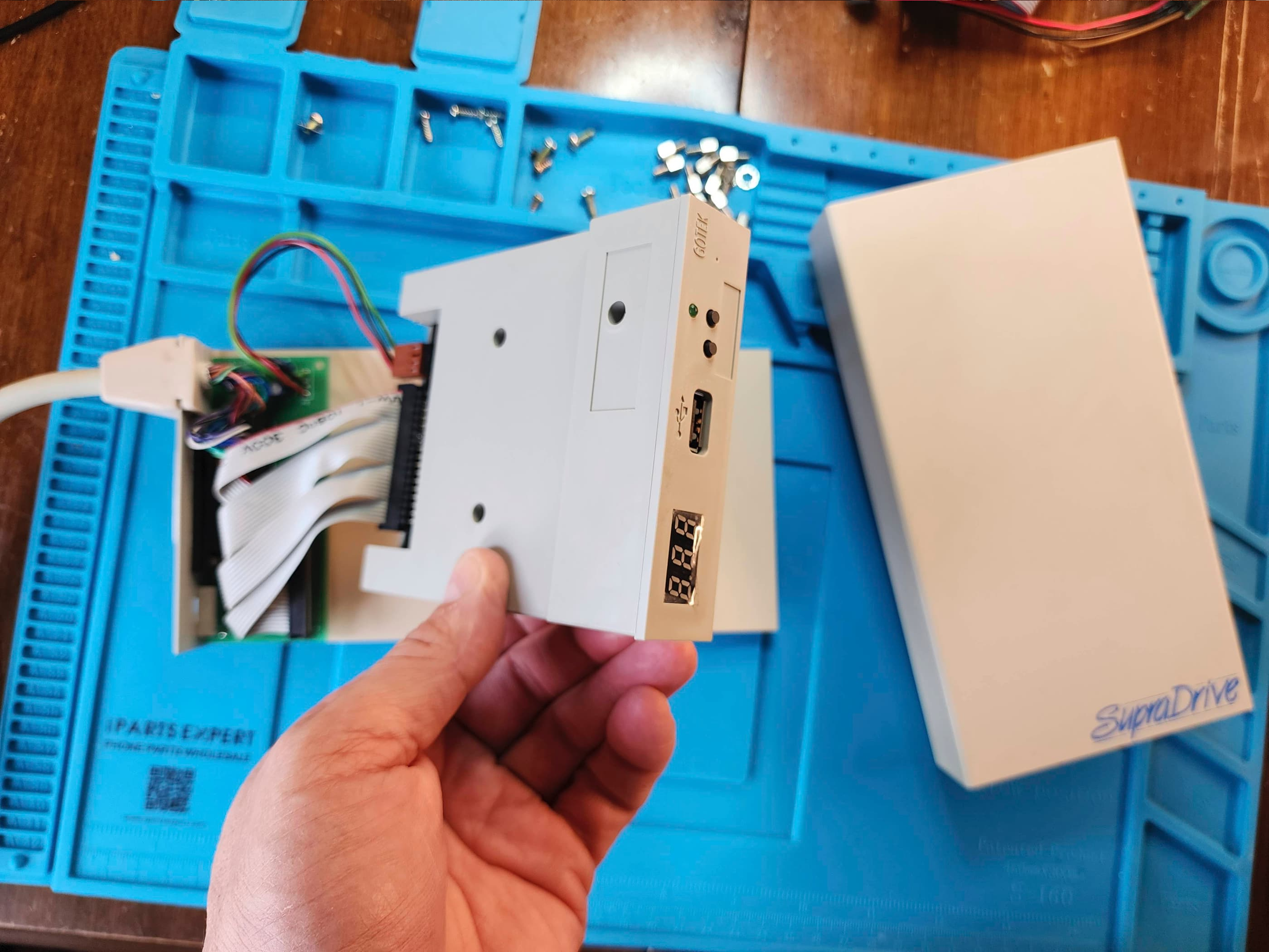
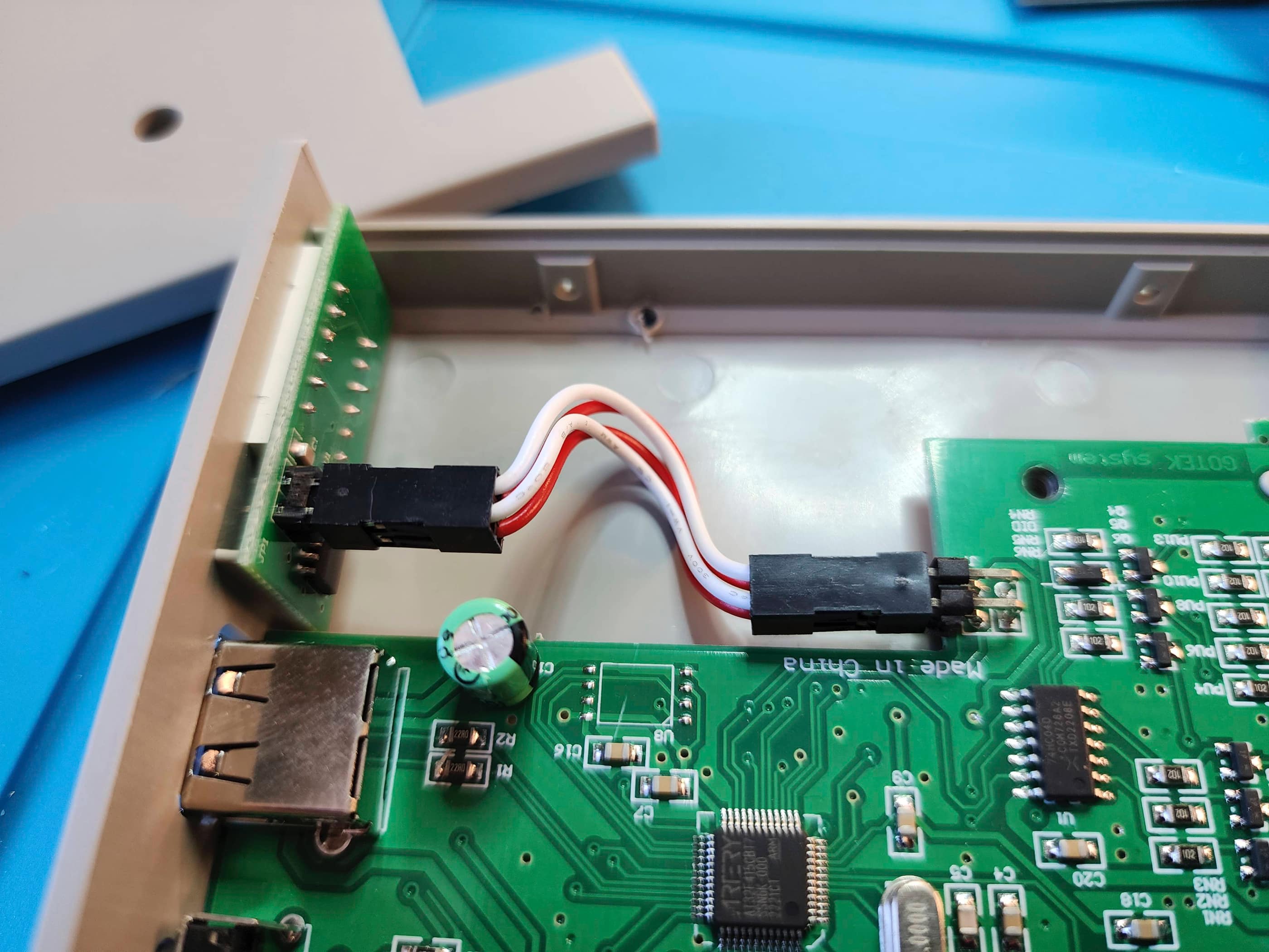
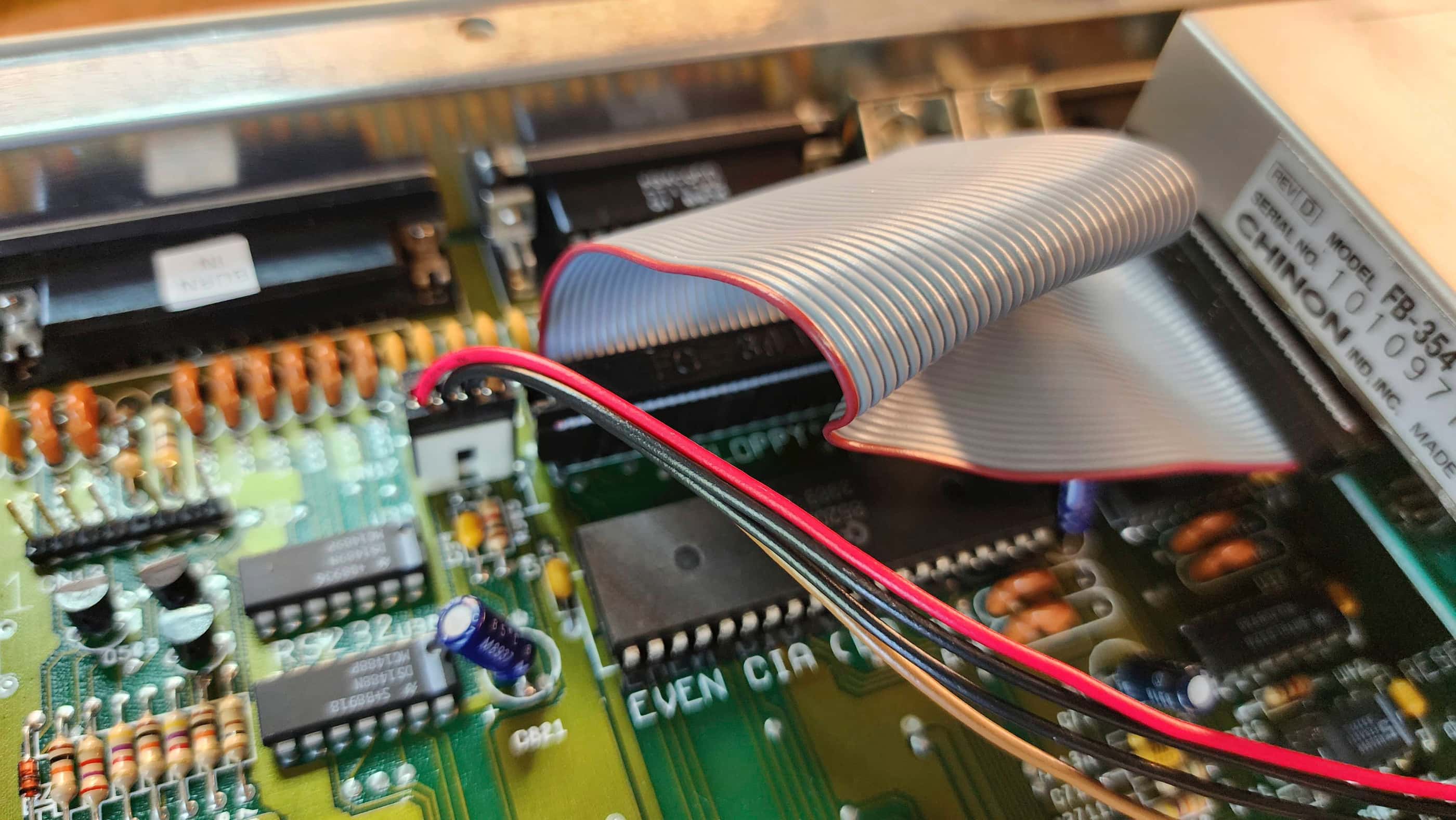
With the case removed for repair, I got to work on testing. The first thing I did was check the voltages on the OEM power supply. Even though everything came back well within spec, I still opted to replace it with a new power supply from Keelog. I also ordered in a Gotek drive to mount inside the last vestige of my original A500, my non-working Supra external drive. Further, to go along with the Gotek, I also ordered in a Switchless Boot Selector mod that fits on top of the Even CIA chip, so that I could boot from either the internal floppy or from the Gotek.
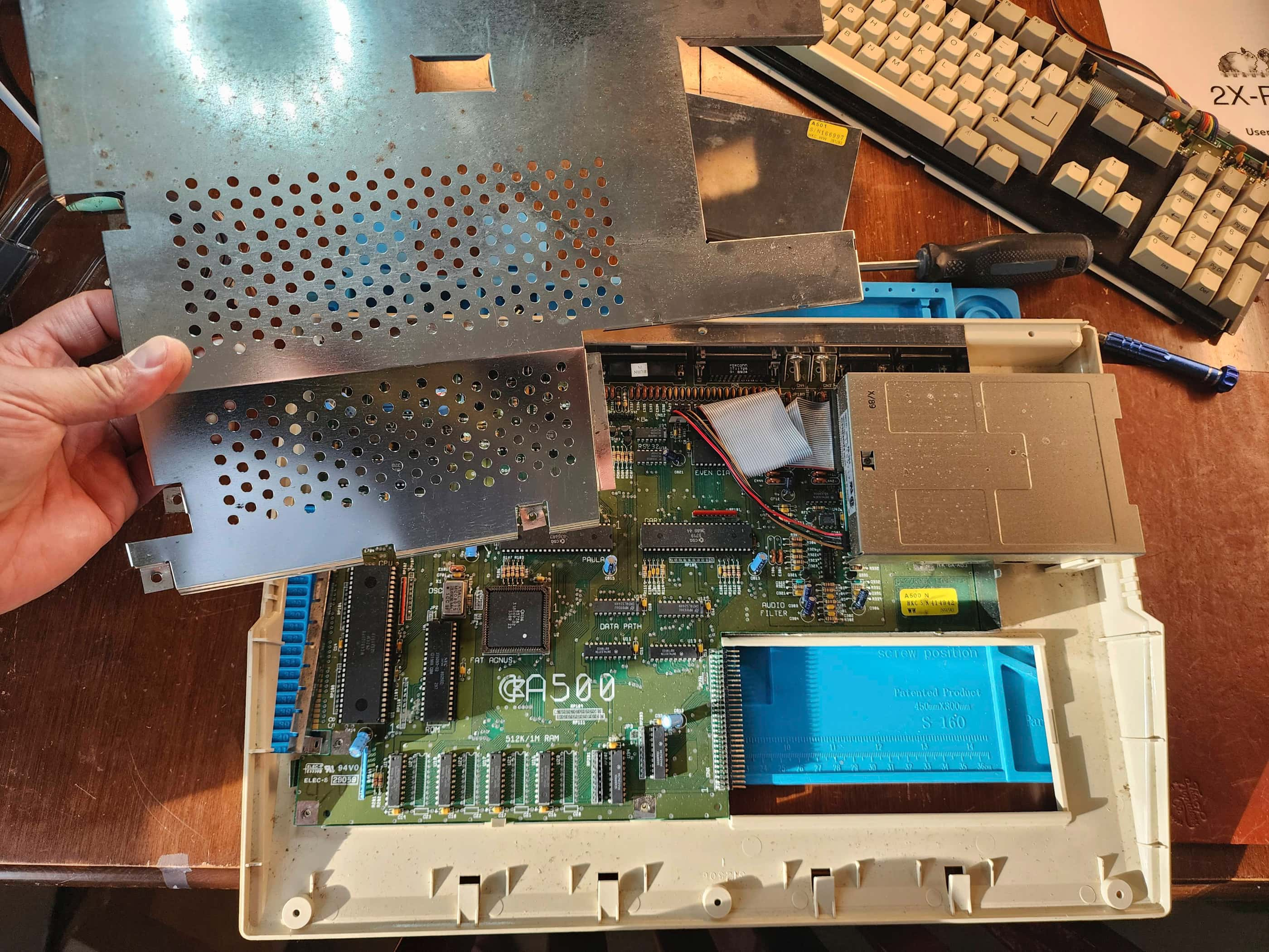
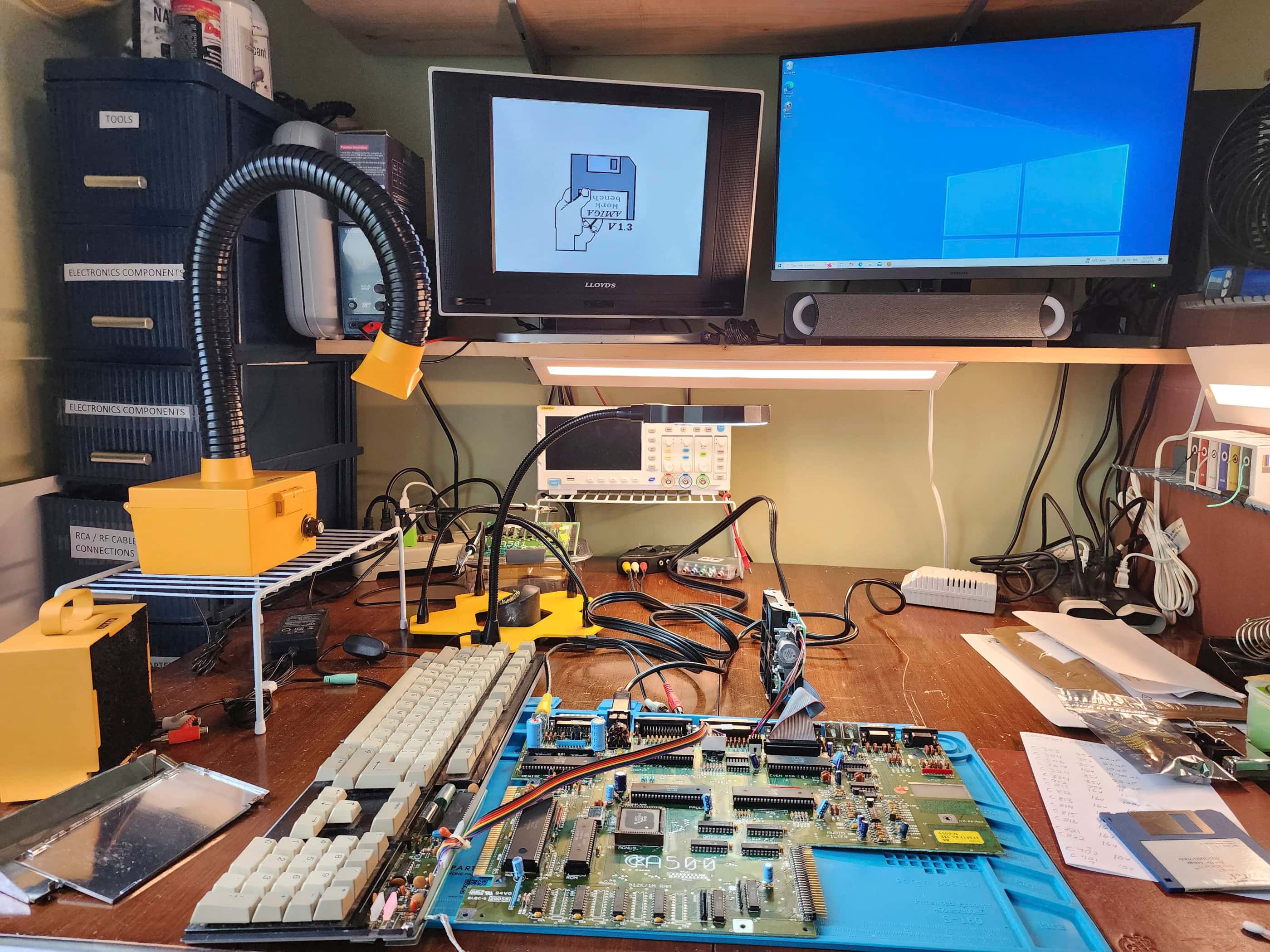
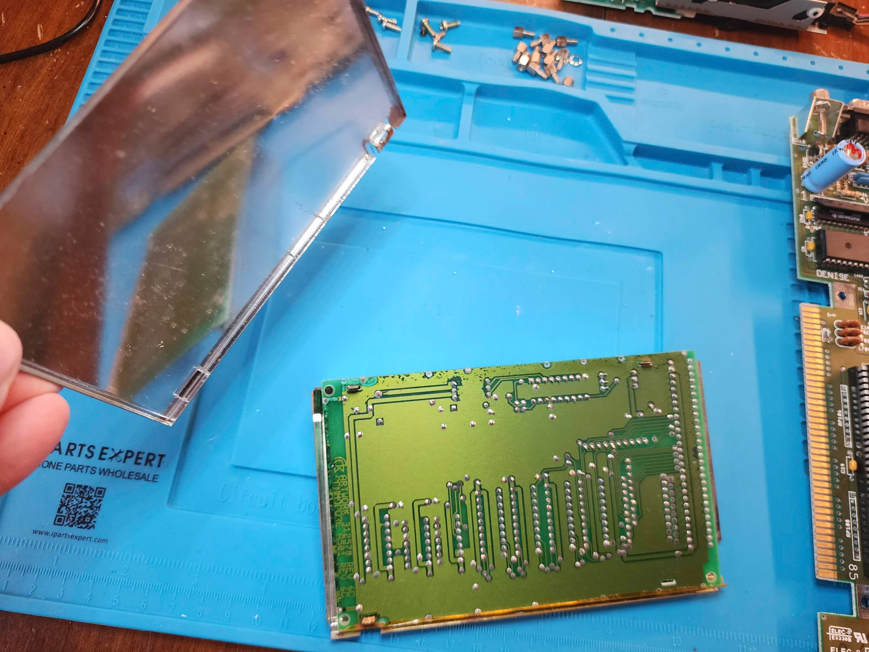
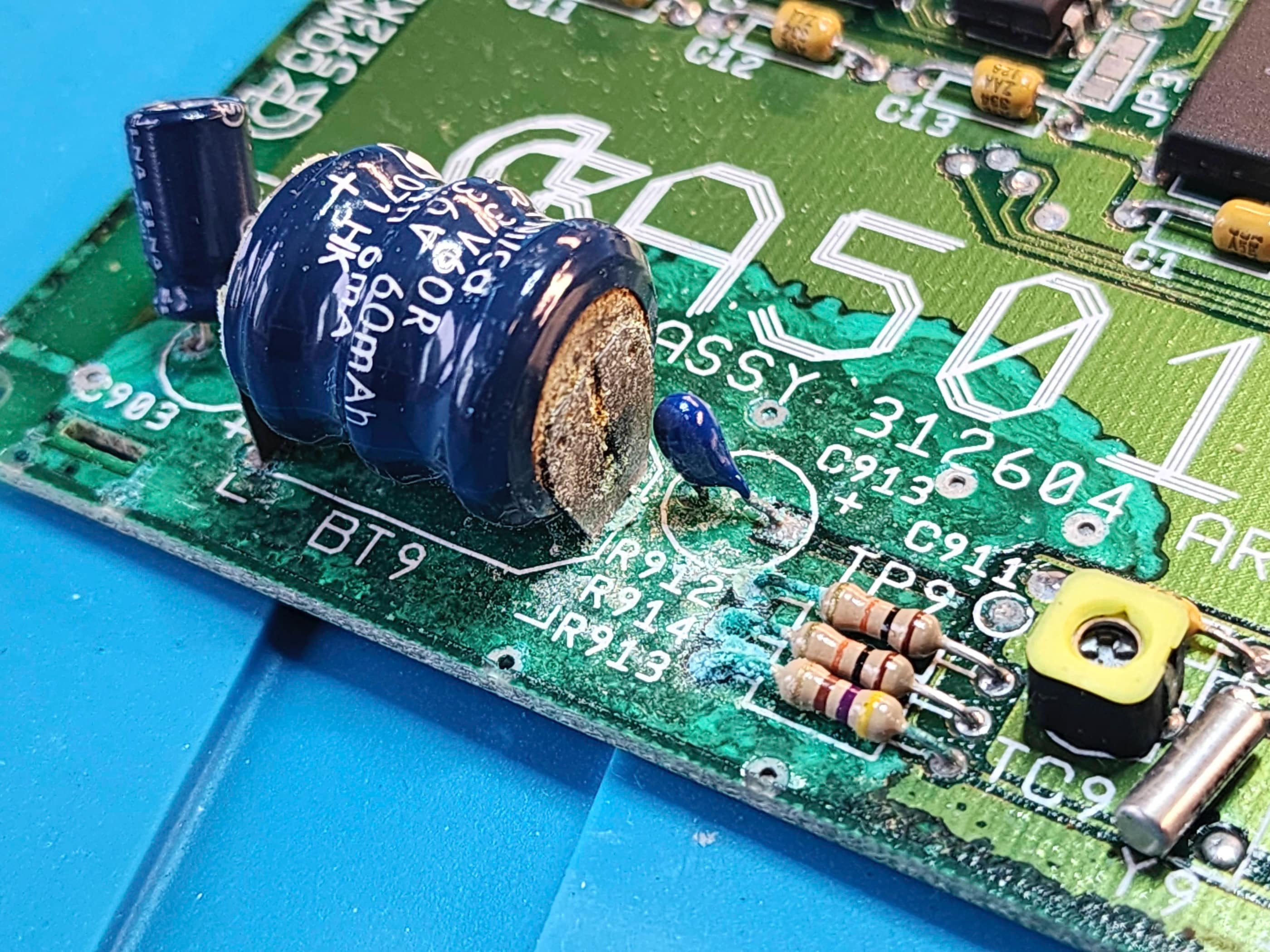
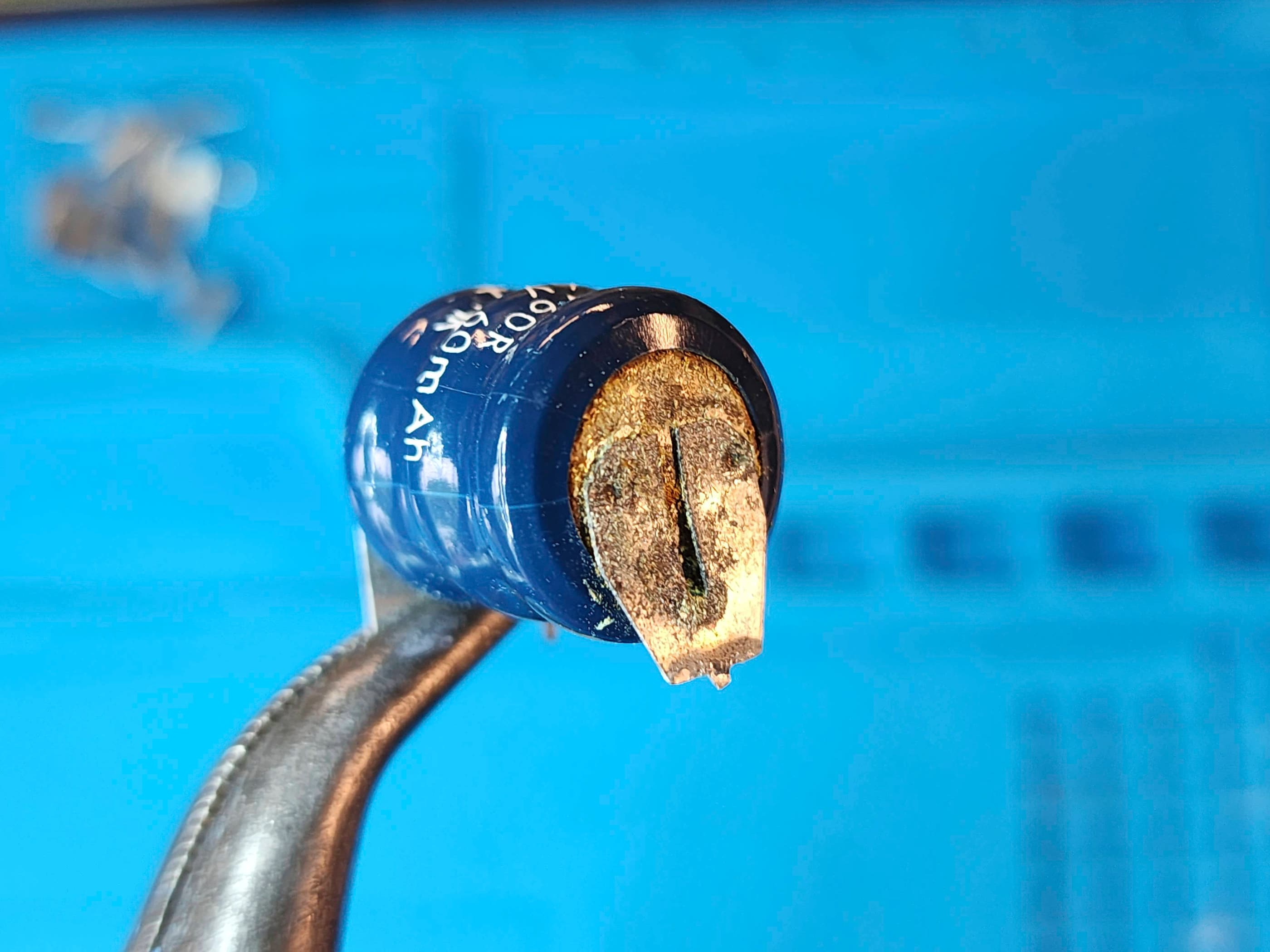
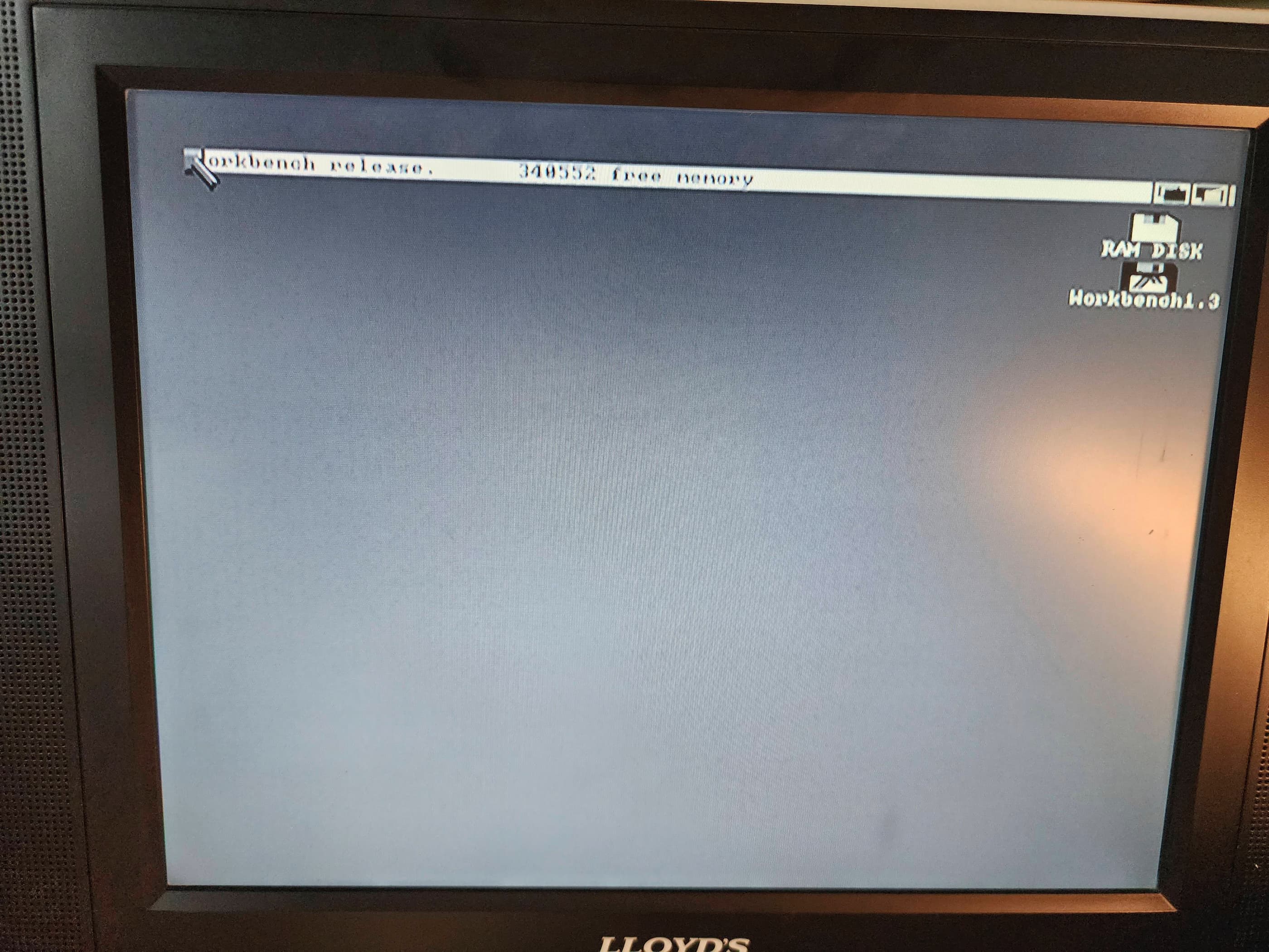
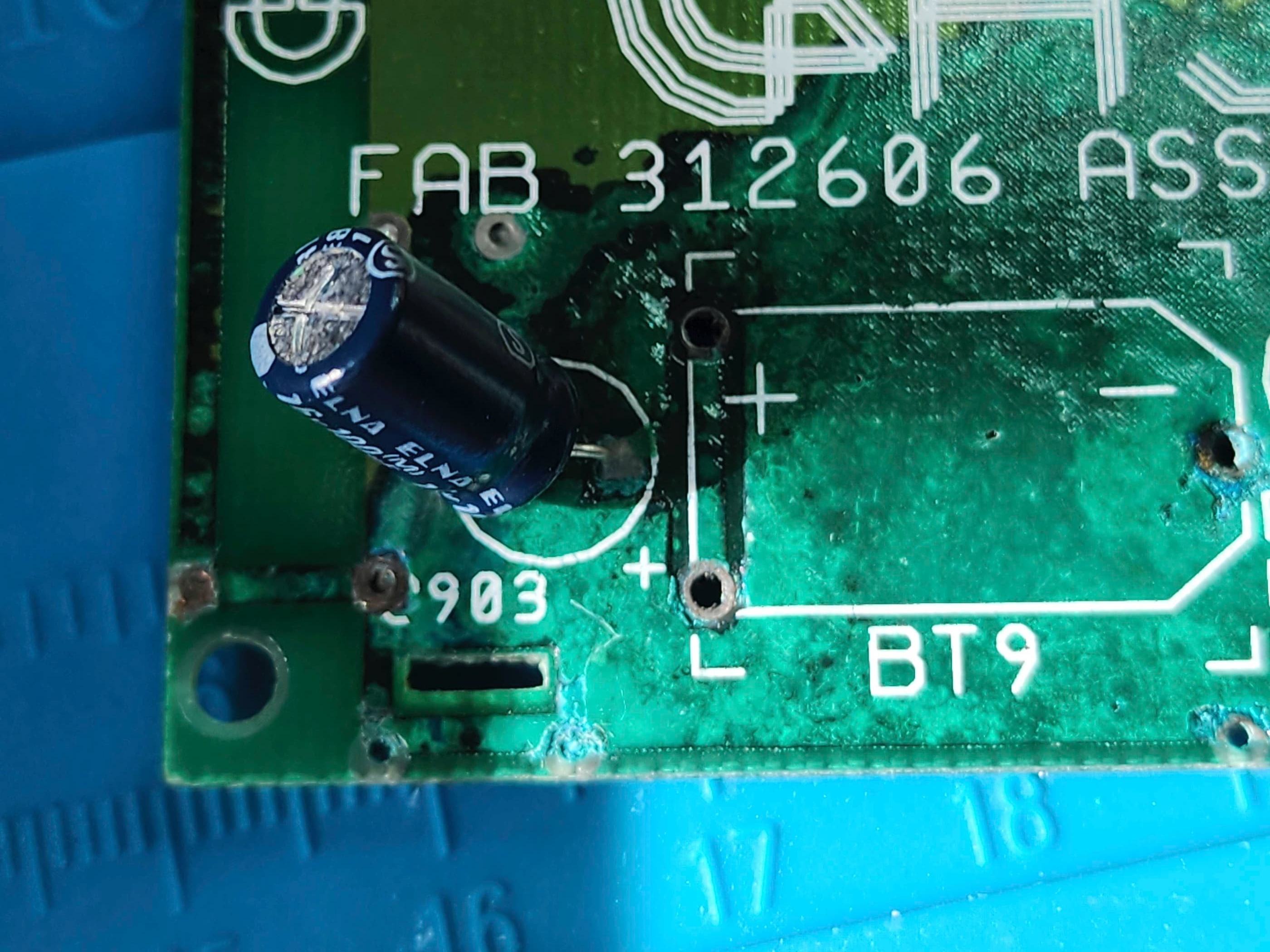
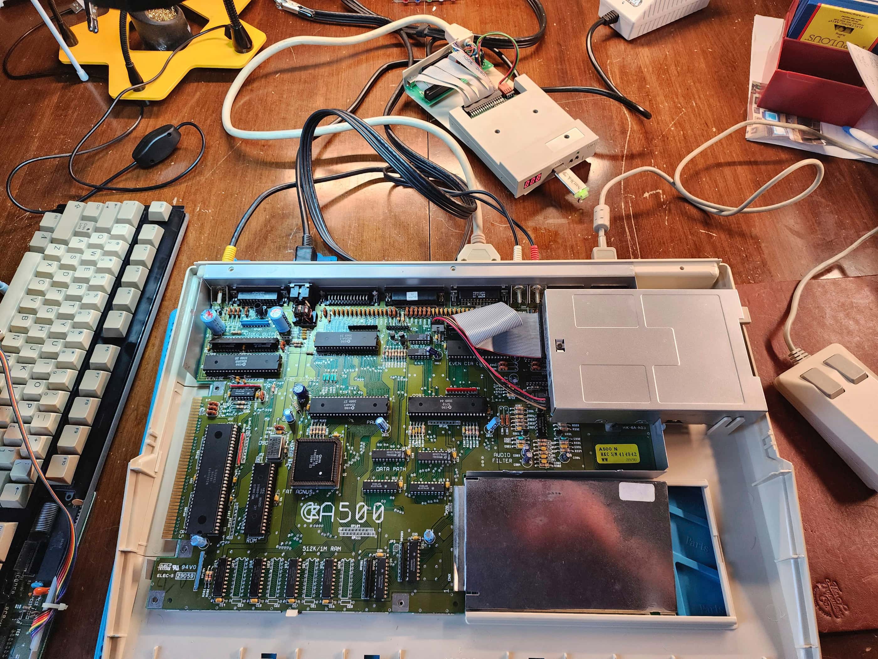
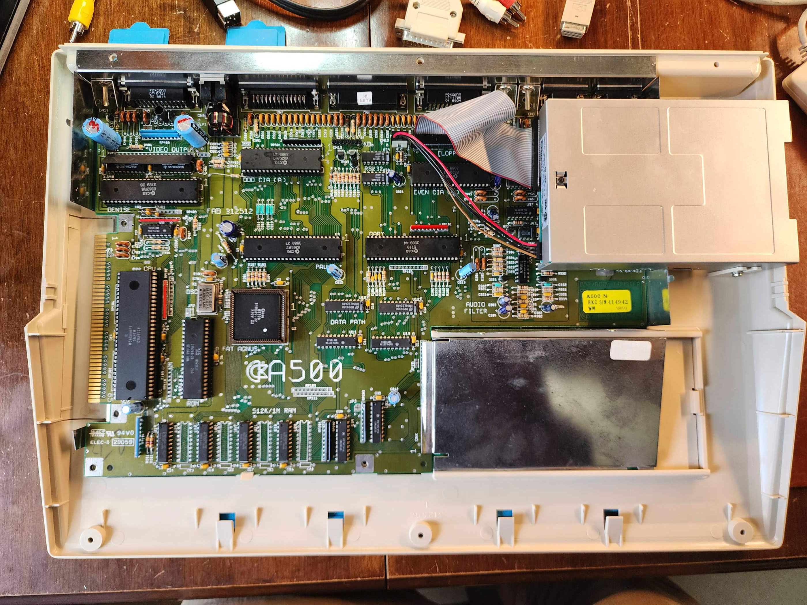
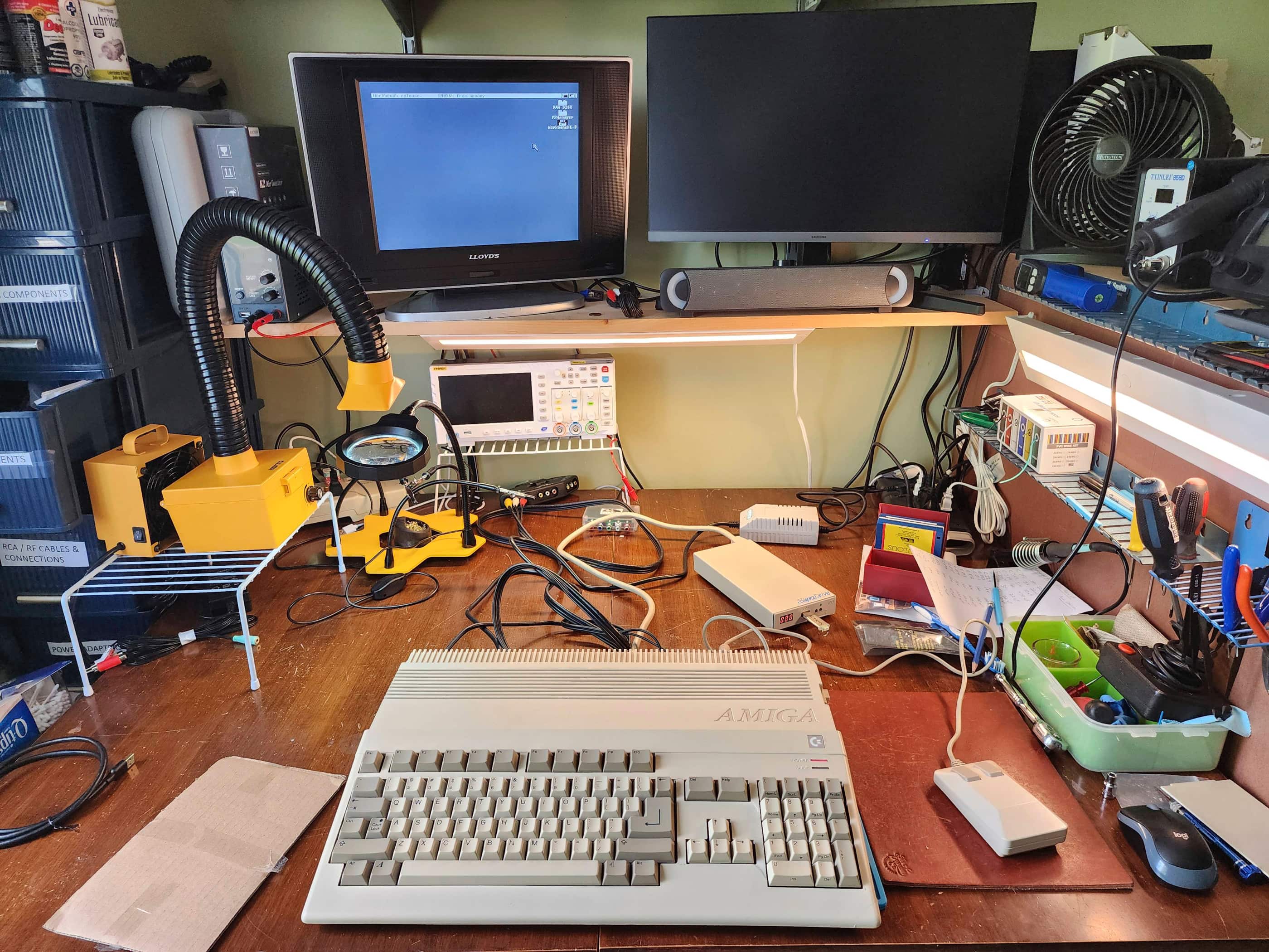
With the new power supply and other parts on hand, I used the B&W composite output for testing (along with an A520 adapter to see things in colour; though I soon acquired a 1084S monitor thanks to my brother-in-law). Thankful to see Workbench 1.3 boot, I noticed right away that the 512K expansion module was not registering. Knowing that the RTC battery had more than likely leaked, I proceeded to remove it and desolder the RF shielding that enclosed it.
Sure enough, the battery had leaked and had caused extensive damage to the board. After desoldering the battery, I then tried to clean-up the corrosion with vinegar and with IPA. Once it looked presentable, I attached it back onto the motherboard and fired up the computer. No dice.
Using my eyes along with a continuity tester to look for broken traces, I failed to find a reason why it didn’t work. I also used Deoxit D5 to clean the male pin header on the motherboard along with the female header on expansion board. Still no dice.
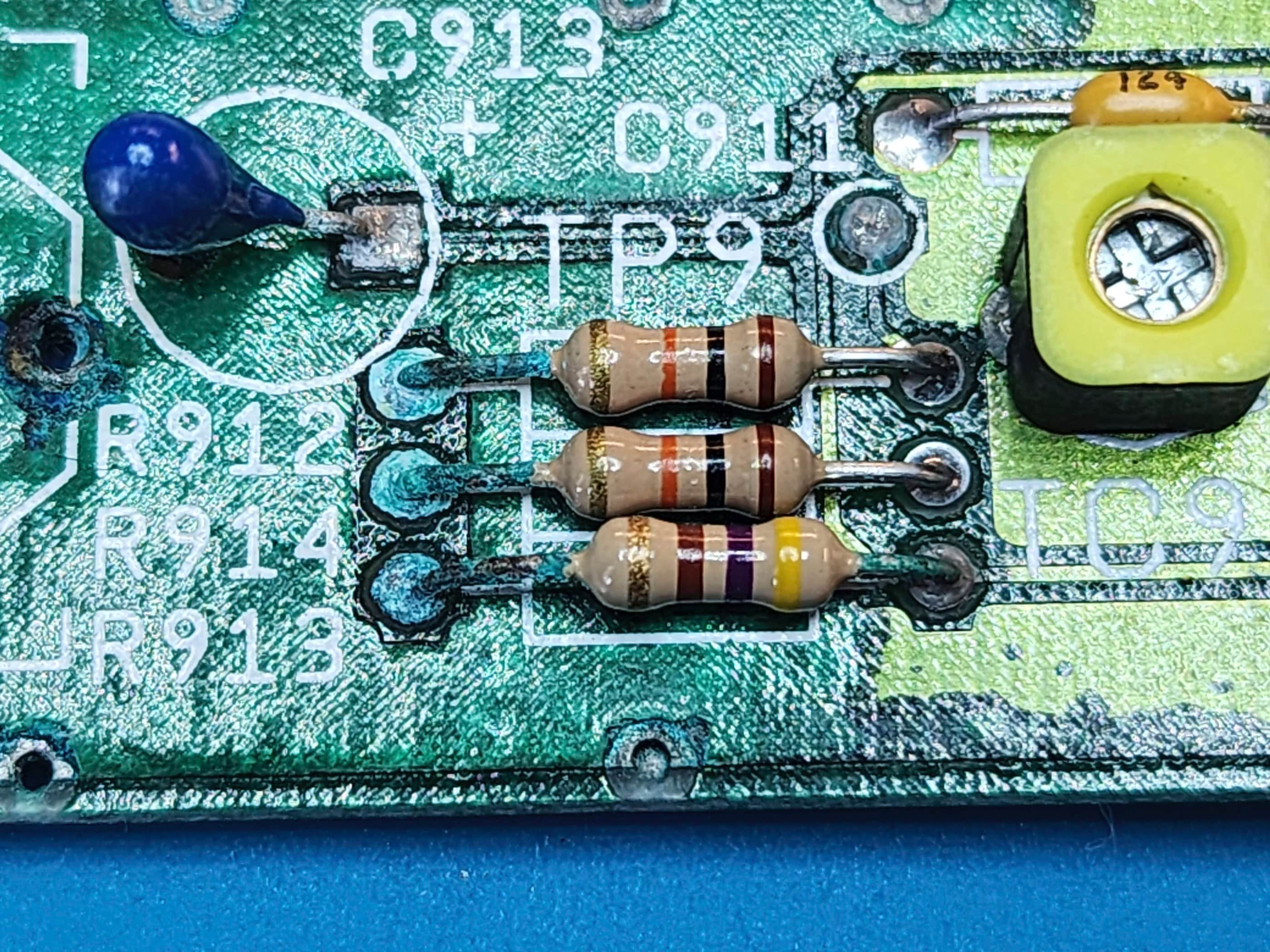
That’s when I decided to replace the electrolytic capacitor and the three resistors that were all in the path of the battery’s carnage. For good measure, I also replaced the only other electrolytic capacitor on the board. I then plugged it into the motherboard and SUCCESS! The computer recognized the additional memory and it was back up and running. Without the RTC, my Amiga thinks it is either 1978 or 1988 when it is turned on, but I’m good with that for now.
Next, I proceeded to give the board a thorough cleaning with IPA along with re-seating and treating all of the socketed chips with Deoxit. An inspection of the capacitors did not turn up anything suspect, so I was happy to leave these alone. Had the OEM power adapter tested out of spec, I might have thought about replace the two (C401 & C402) 10v 3300 uF ones, but they seemed to be okay. I then proceeded to carefully clean the 3.5” floppy drive.
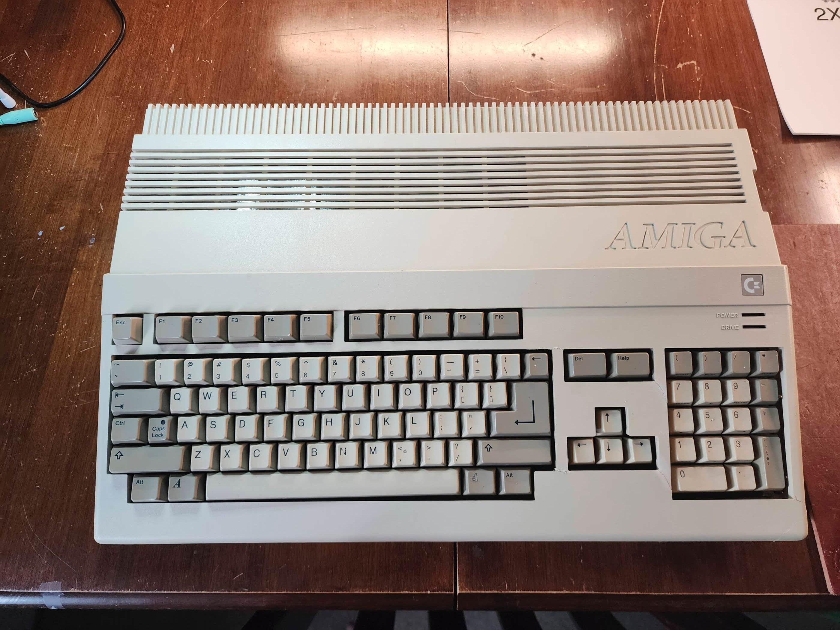
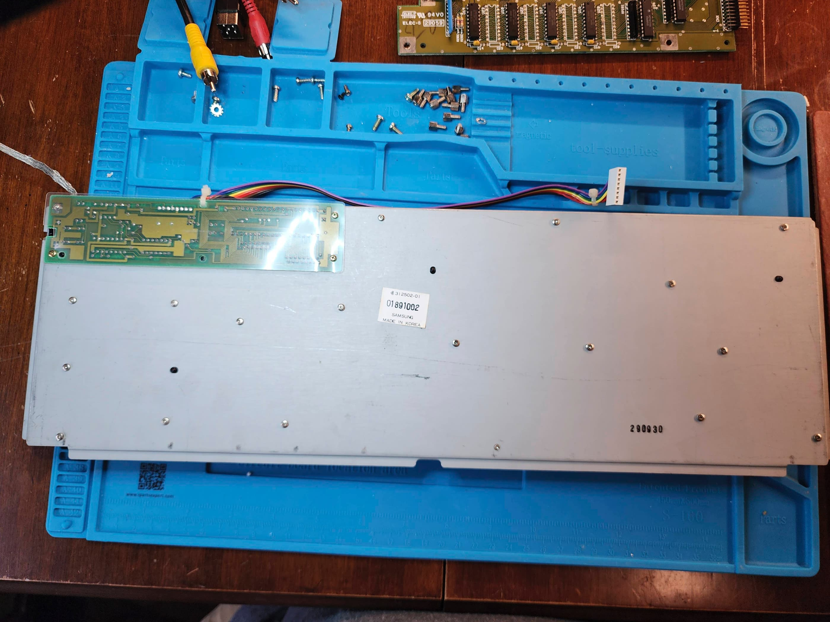
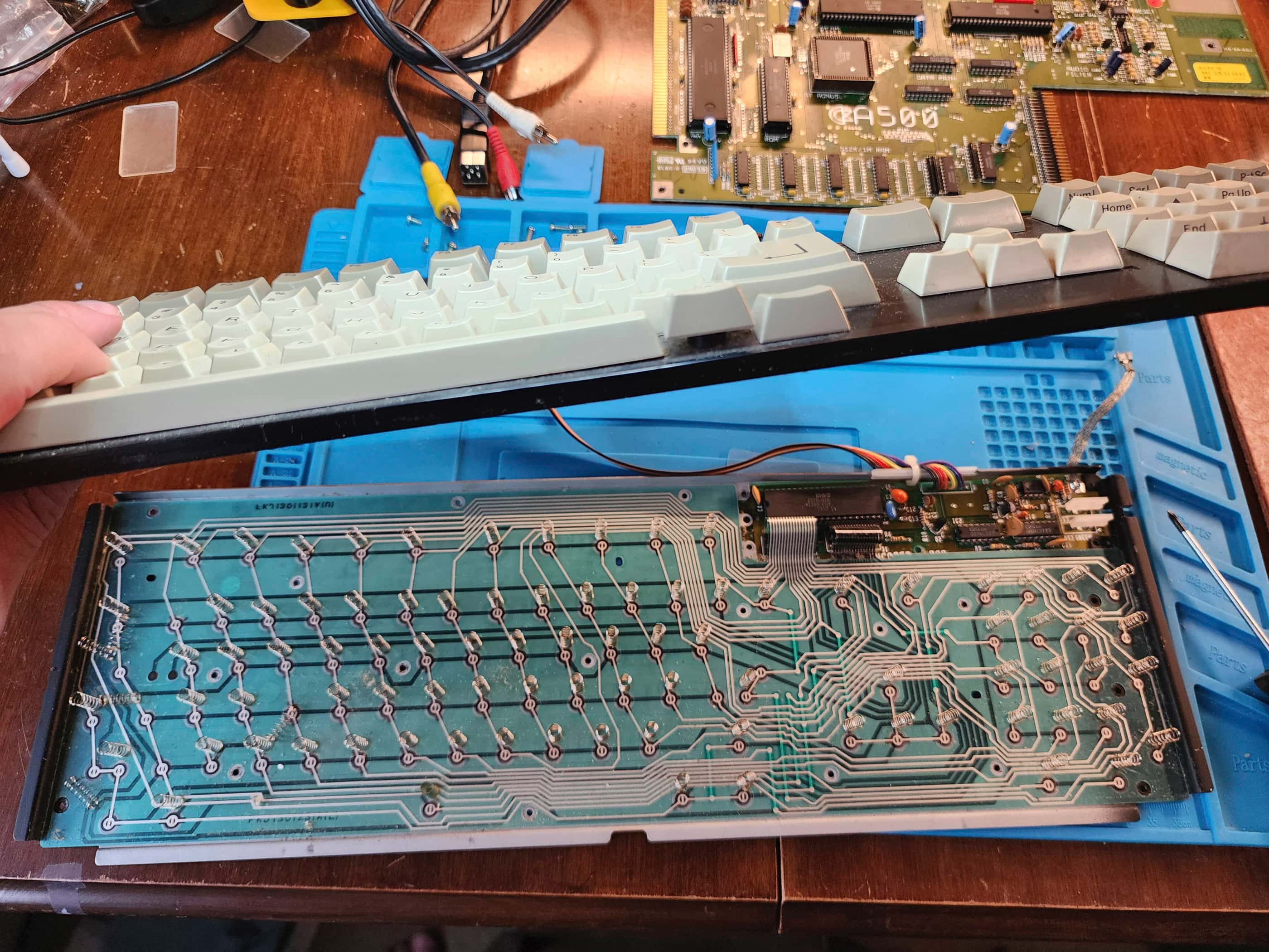
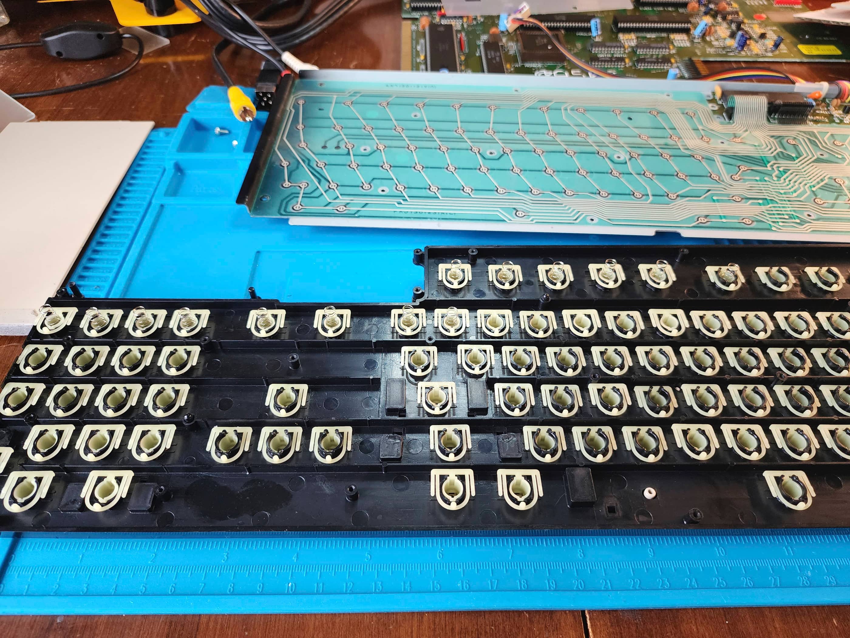
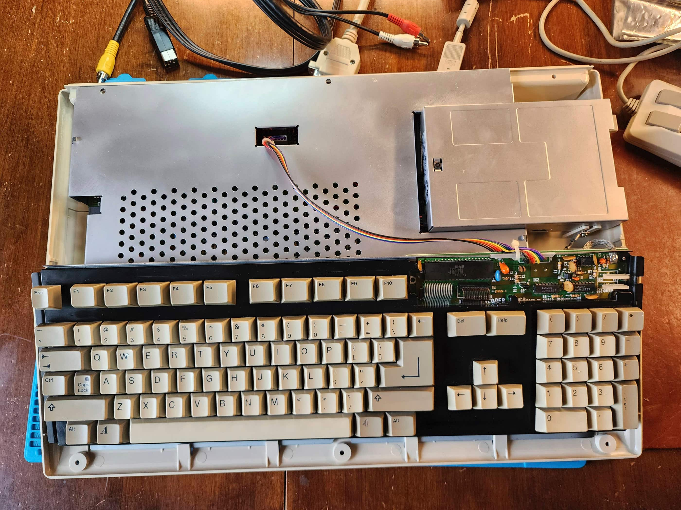
The keyboard was next, and I was surprised to see that it was a Samsung and not a Mitsumi. I was even more surprised when I removed the keyboard layer and saw all the springs standing upright on the mylar flex circuit. I carefully gathered these up so as not to lose any but somehow, I still managed to lose one. Fortunately, I could replace it by winding down a spring from an old Sega Genesis power button.
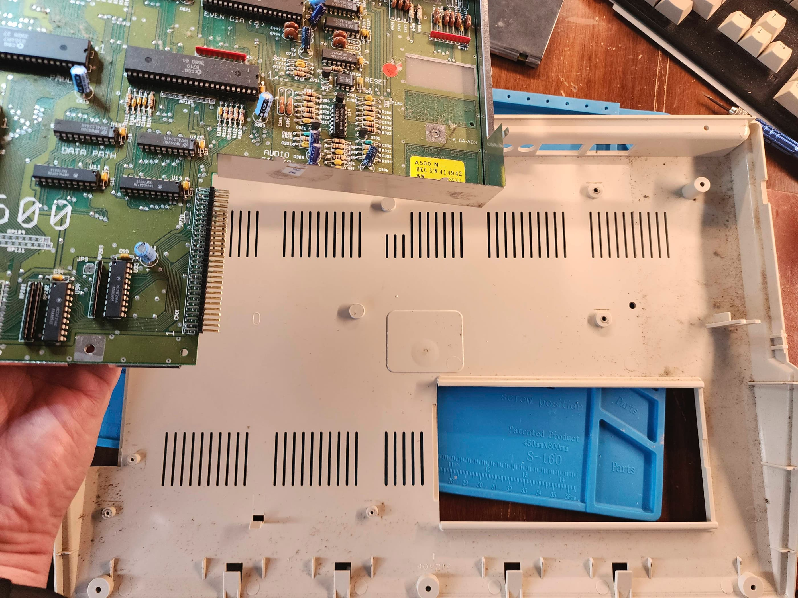
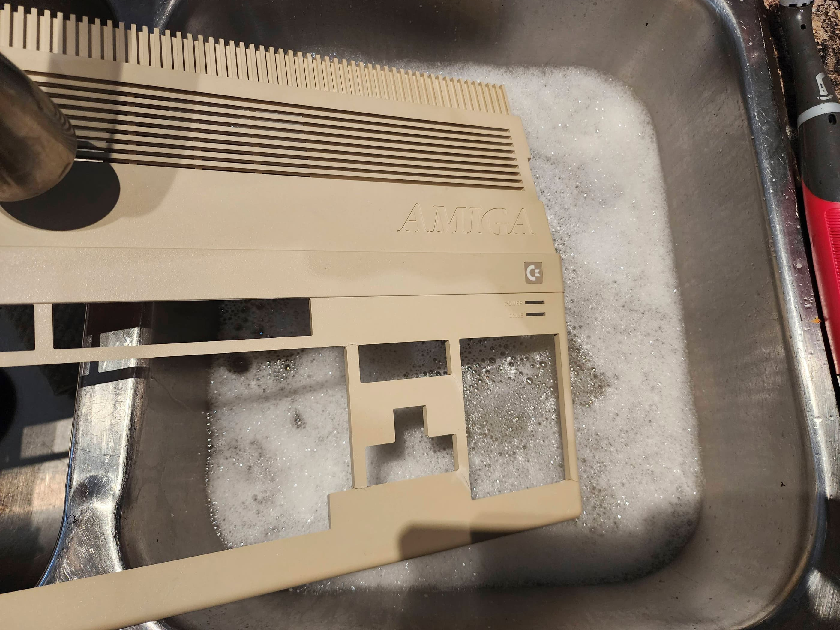
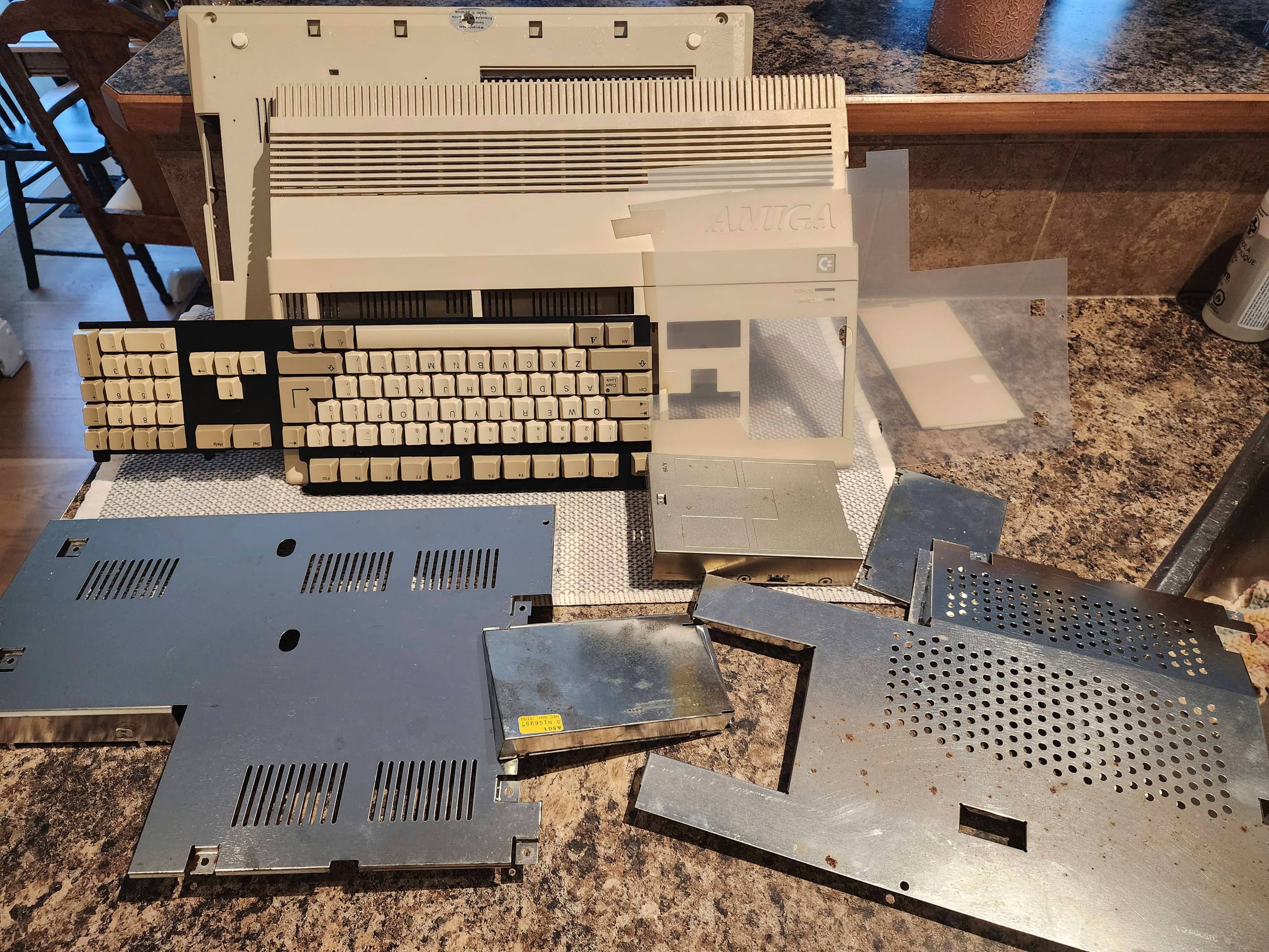
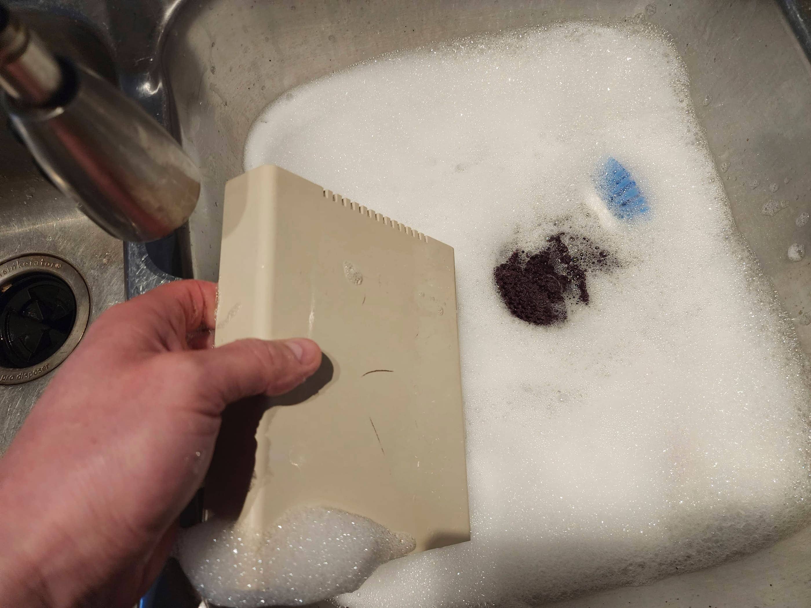
With the keyboard removed, I washed it along with the case. As the top half of the RF shielding was quite rusty, as was the top case of the floppy drive, I soaked these in vinegar before scrubbing off the rust with steel wool. As an experiment, I spray-painted only the top of the RF shielding with Rustoleum and then did the same for the drive case. I did not spray paint the sides of the shielding or where it made connection with the bottom shielding. It certainly looked better than it did before, so I may try this limited action on another unit.
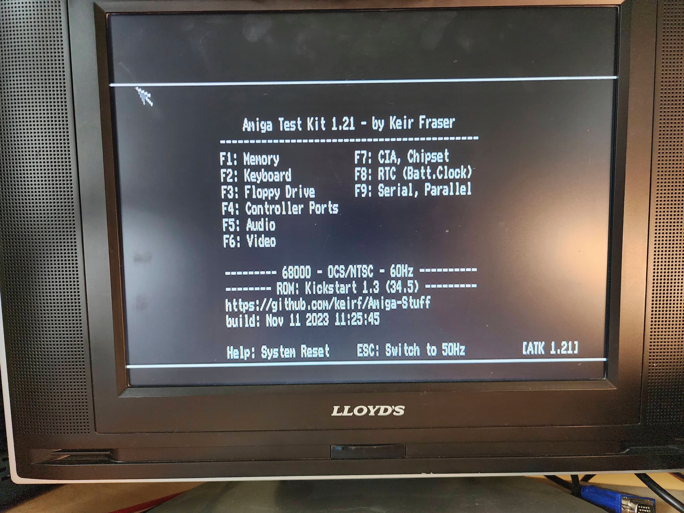
Once the keyboard was dry and the mylar circuit clean, I re-assembled the keyboard. I then connected everything up to the motherboard including the Gotek which I had configured using the retrofriends’ tutorial which I had preloaded with Amiga Test Kit from Kier Fraser. After running it through all the tests and seeing everything pass, I partially reassembled the entire unit while I waited for my switchless boot selector to arrive.
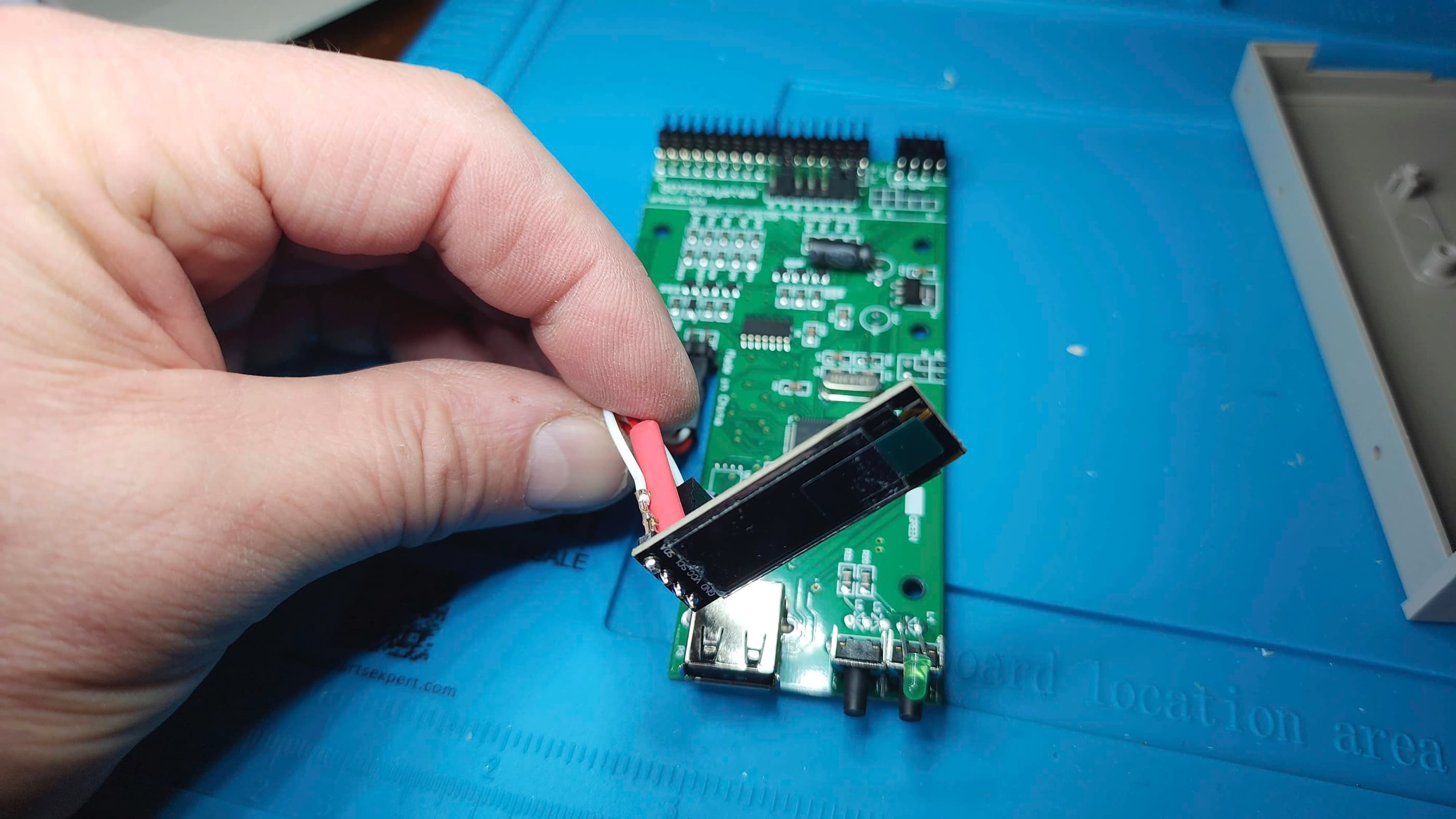
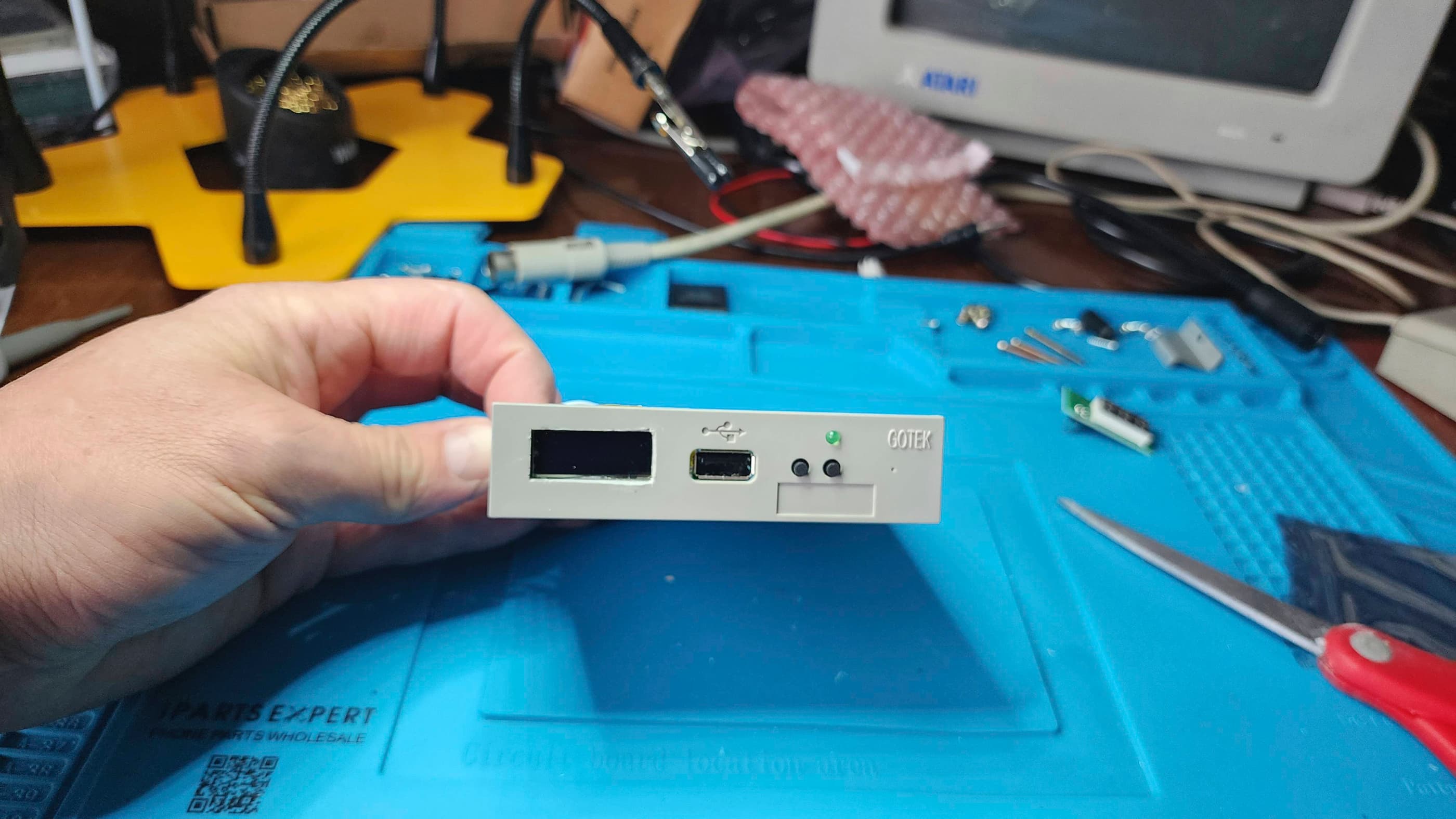
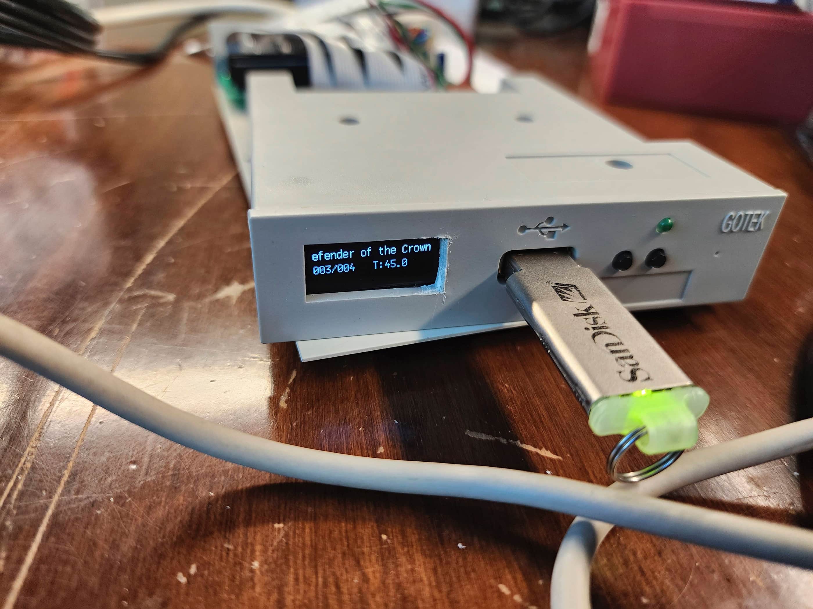
While waiting for the boot selector, I decided to modify my Gotek even further by adding an OLED screen using yet another great tutorial from retrofriends. This is one mod that I 100% recommend doing as it makes the functionality of a Gotek so much better!
After modifying the Gotek, I was excited to have the switchless boot selector arrive. However, for whatever reason, I could not get the selector to function. Troubleshooting included inspecting the correct alignment and seating of the selector inside the 8502 Even CIA chip socket and also the correct seating of the Even CIA in the selector socket. As the default was set to boot from DF0 (3.5” floppy), toggling to boot from DF1 (Gotek) was supposed to be accomplished by hold the reset key sequence for 4+ seconds or performing the reset sequence 3 times in a row.
Yet, once the boot selector was installed, I could not boot from either DF0 or DF1. In fact, the power seemed to disappear from DF0 altogether. Hmmm… 🤔 I then removed the boot selector and put the Even CIA back into its original socket and powered everything up again. This time DF0 functioned as normal. After trying two or three more times, including trying to set the Gotek up as DF0 by removing it from its current housing, nothing happened. Finally, I tried doing everything over gain with a different switchless boot selector, all with the same results.
Since this should be a very simple procedure (see this tutorial by Bits Bytes & Bourbon) I was at a loss as to why I couldn’t get either selector to work. I’ve since made numerous attempts to get things to work and have done detailed checking of both CIA chips and nothing. To date, I simply haven’t been able to figure this one out…
As DF0 works perfectly as a floppy and the Gotek works perfectly as DF1, I simply make physical 3.5” boot disks for games while keeping the subsequent disk .ADFs on DF1. This works, but I’d rather be able to boot directly from the Gotek. That the Gotek won’t work when setup as DF0 in place of the 3.5” drive only adds to the mystery…. 🤔
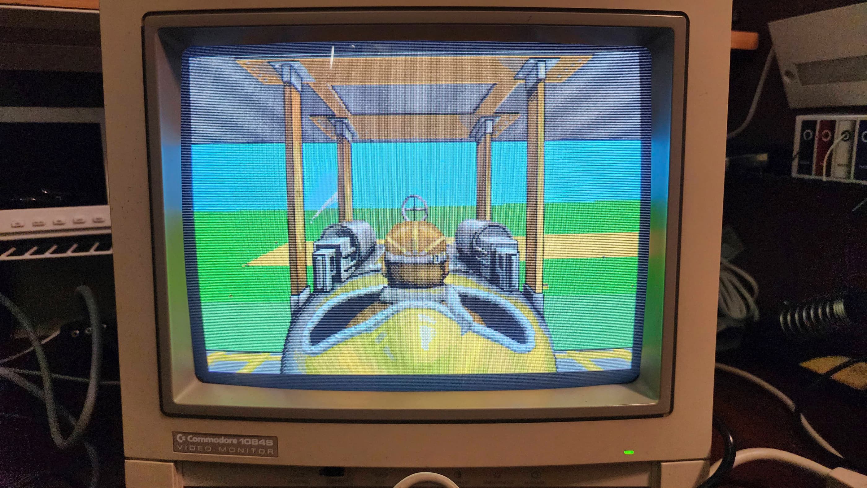
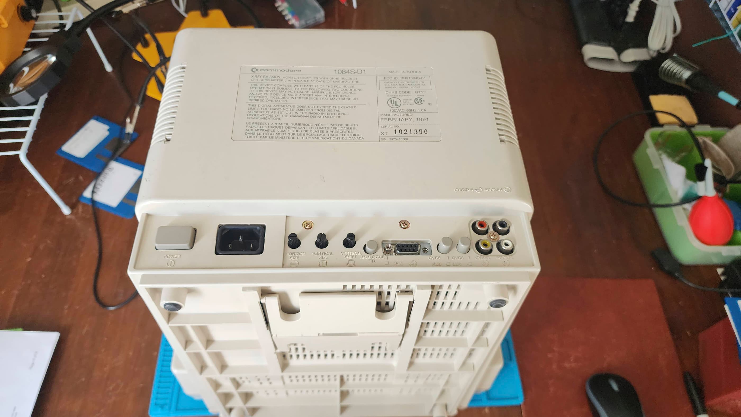
While I was trying to figure out the boot selector mystery, my BIL went to a retro computer show in Calgary and found a working Commodore 1084S monitor for me for $200. It was dirty and missing the front panel cover, but it was a sweet deal.
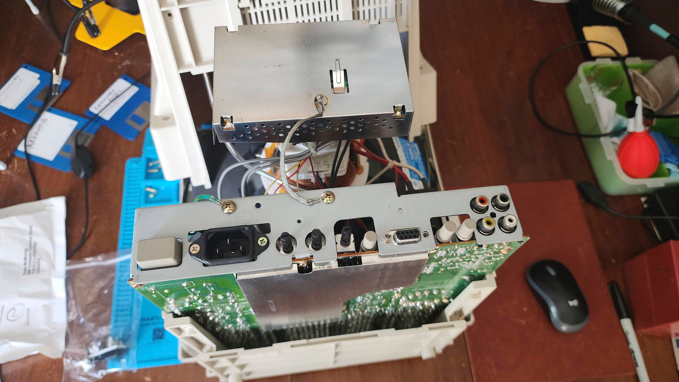
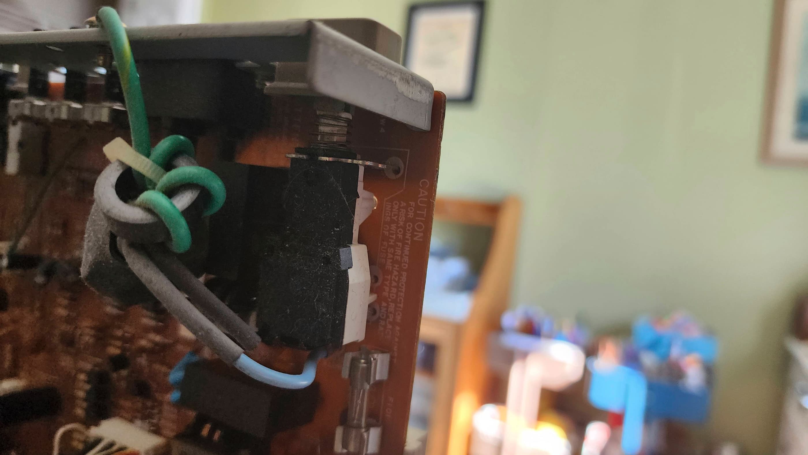
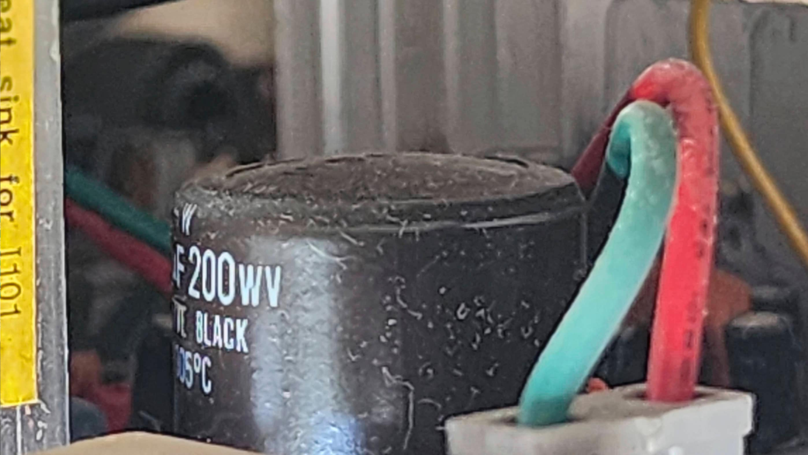
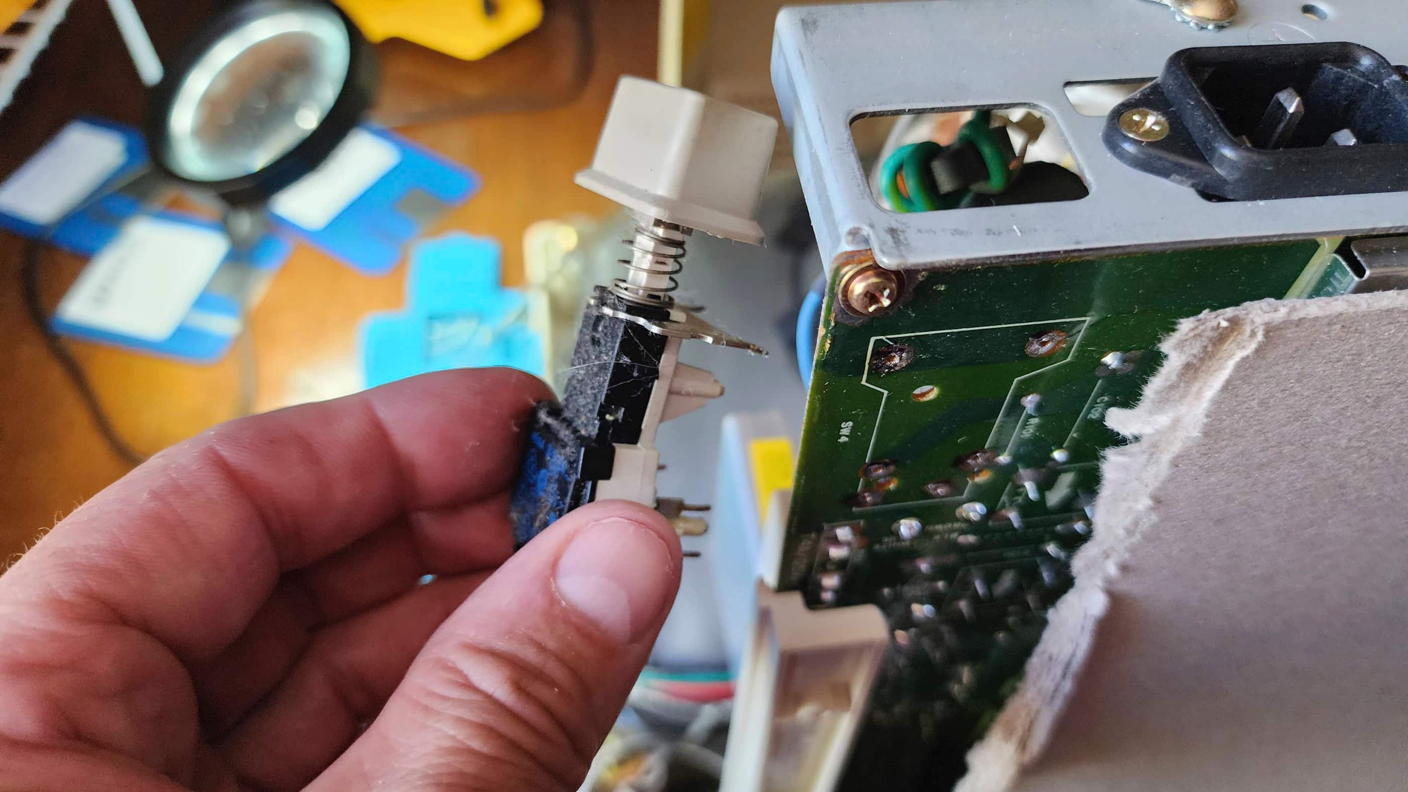
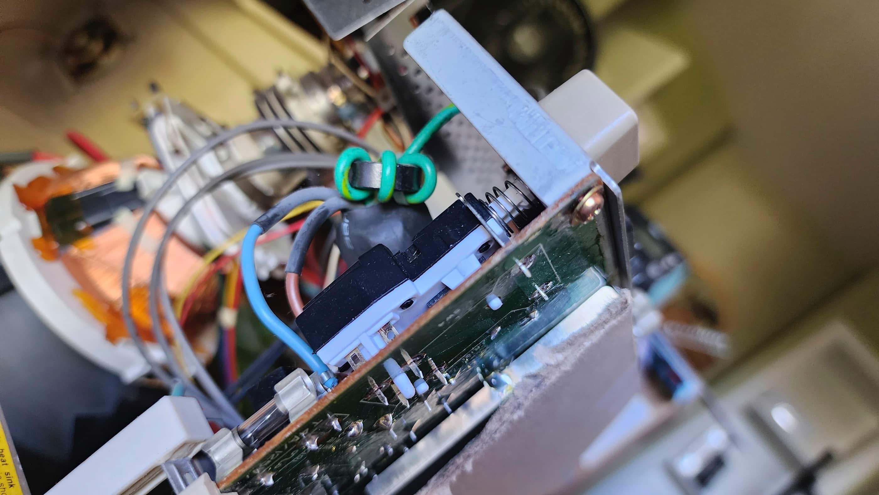
However, after getting it home and using it for a few weeks, the power button gave up the ghost (not uncommon for these monitors) and I was forced to order in a replacement from Poland. When it arrived several weeks later, I found the only mod I needed to do, was to cut off one of the extra contacts. I then de-soldered and removed the old switch and tested the fit of the new one – it fit perfectly! It was an easy solder to install the new switch.
While the monitor was apart, I inspected the caps and gave it a thorough dusting. After I put everything back together, I tested the new switch and it worked without a hitch. The monitor was fixed! I then spent time cleaning the outside of the monitor to give it back some dignity. I will also keep my eyes open for a replacement panel cover.
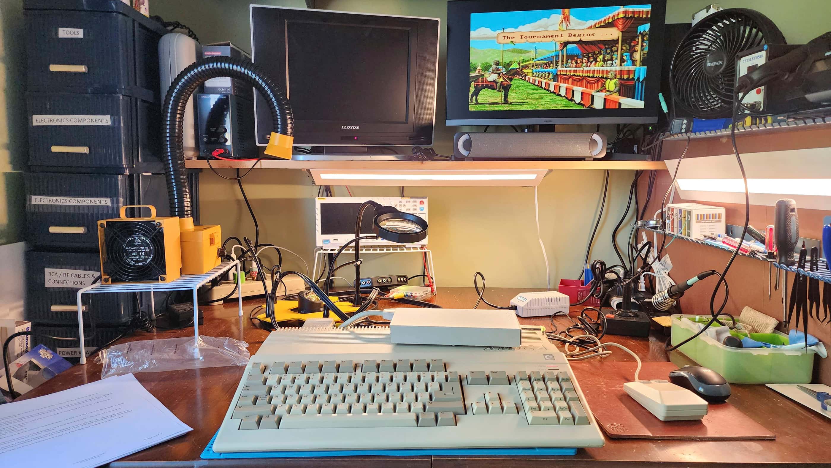
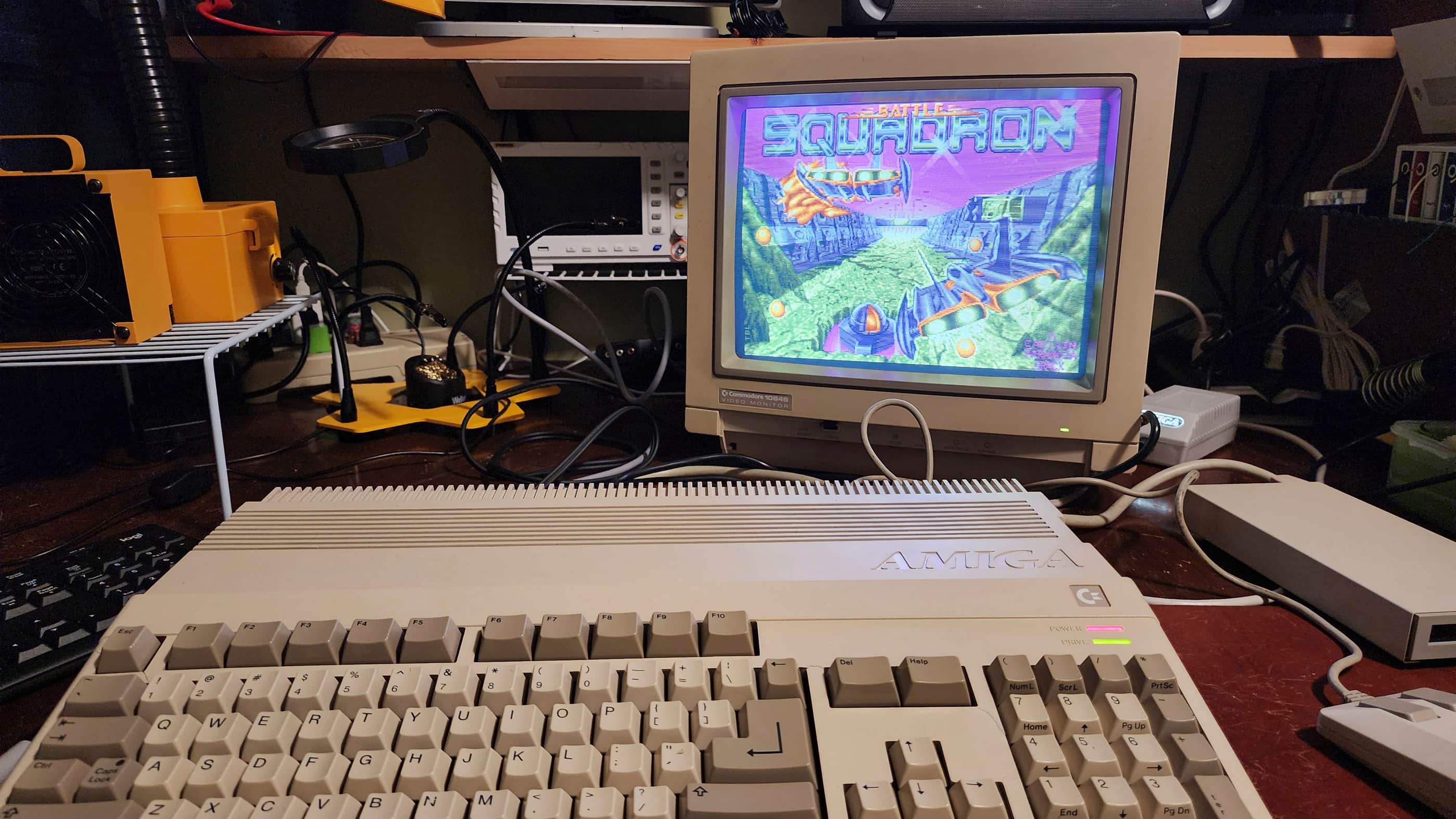
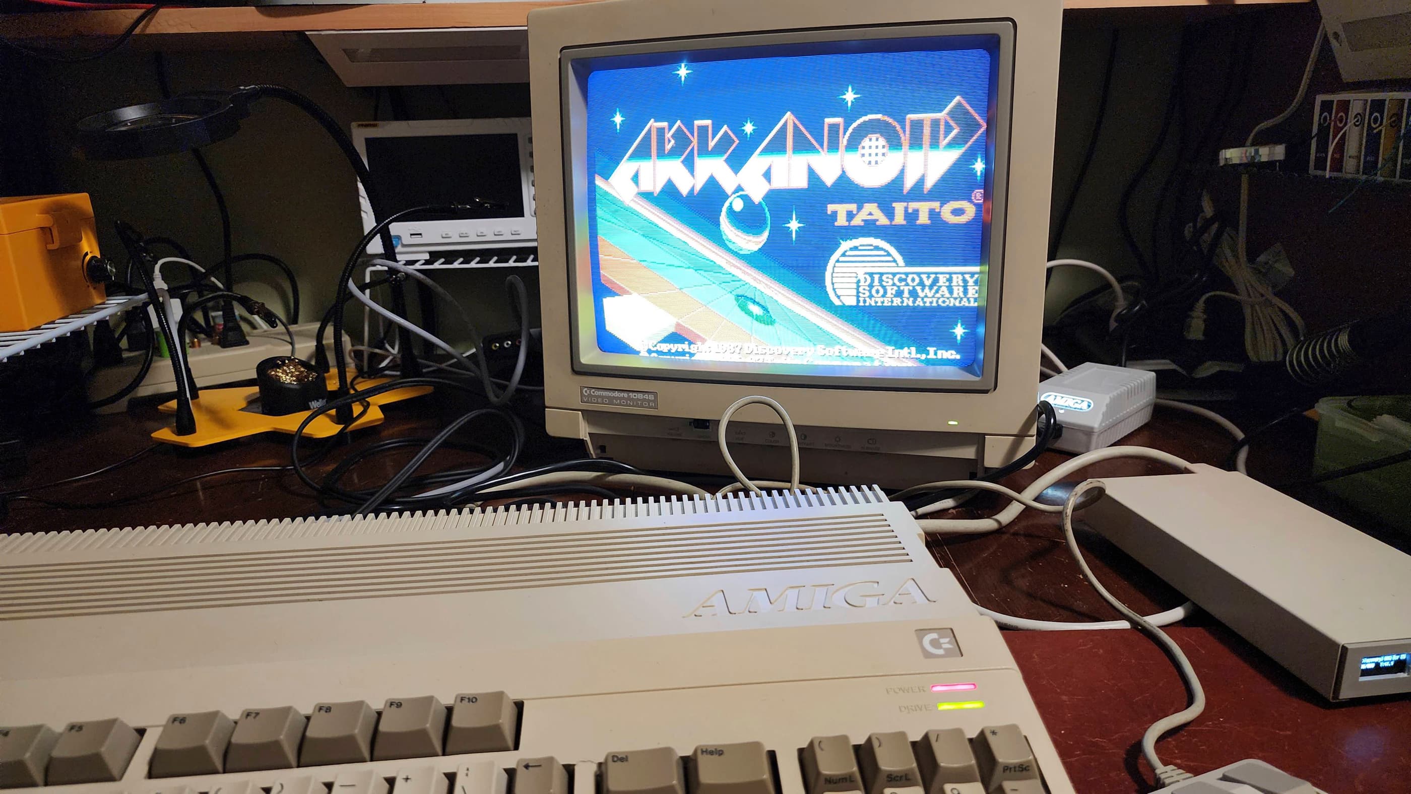
I now have a working A500 and 1084S and I’ve enjoyed playing many of my favourite games over the past few months. I love the Amiga!! 😀
Parts & Products Used: 99% isopropyl alcohol; Chemical Guys Natural Shine; Permetex Plastic Welder epoxy; Deoxit D5; Rustoleum Rust Paint (silver); Keelog Amiga power supply; A501 Expansion: electrolytic capacitors (radial): 16v 100 μF (2); resistors: 10k 5% (2), 460 5% (1); 1084S Monitor: PreH ME5A power switch; Gotek (SFR1M44 U100 3.5); Gotek OLED: 0..91″ OLED Display 128×32 12C Interface SSD1306 DC3-5V

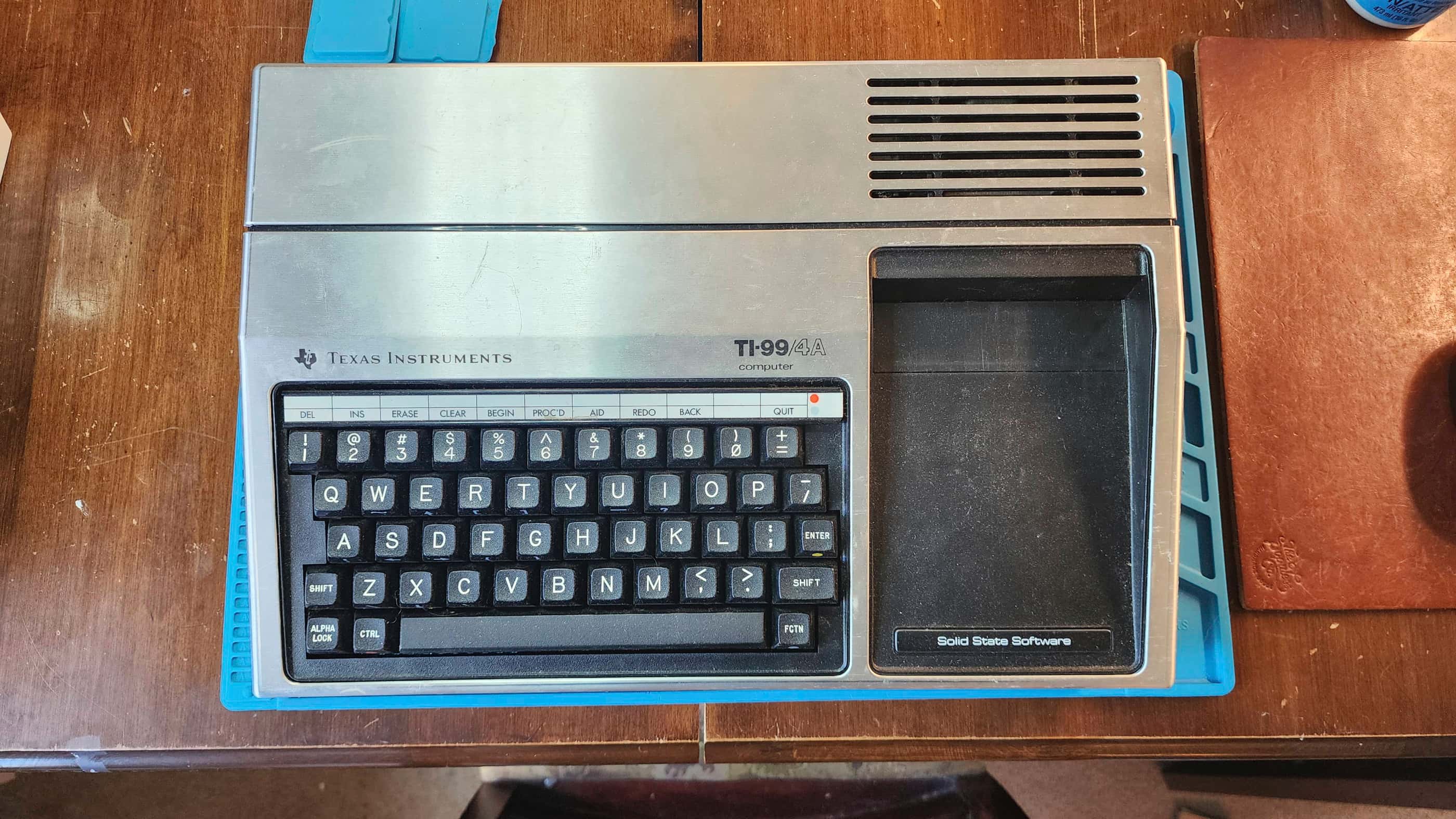
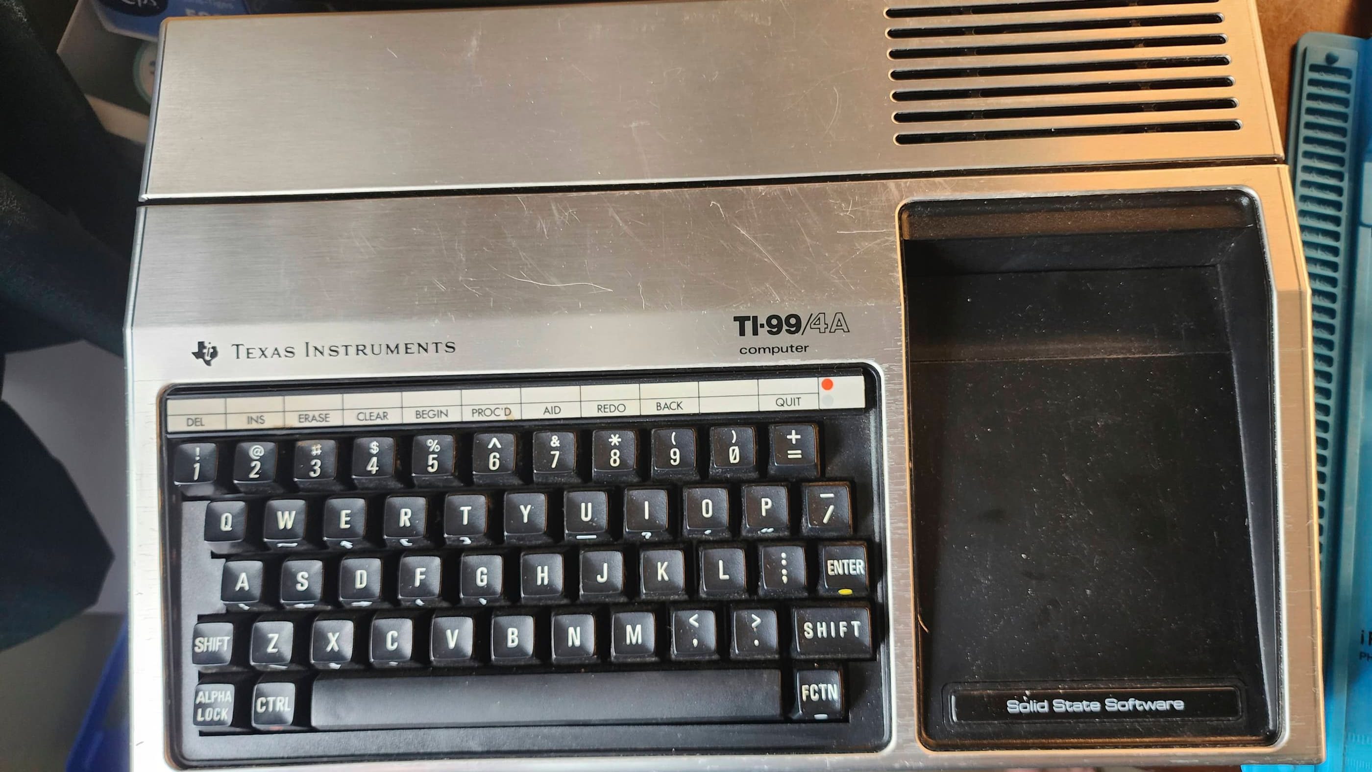
Texas Instruments TI99/4A #1
Years (1981-1984)
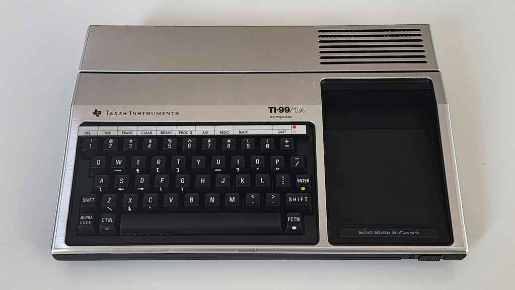
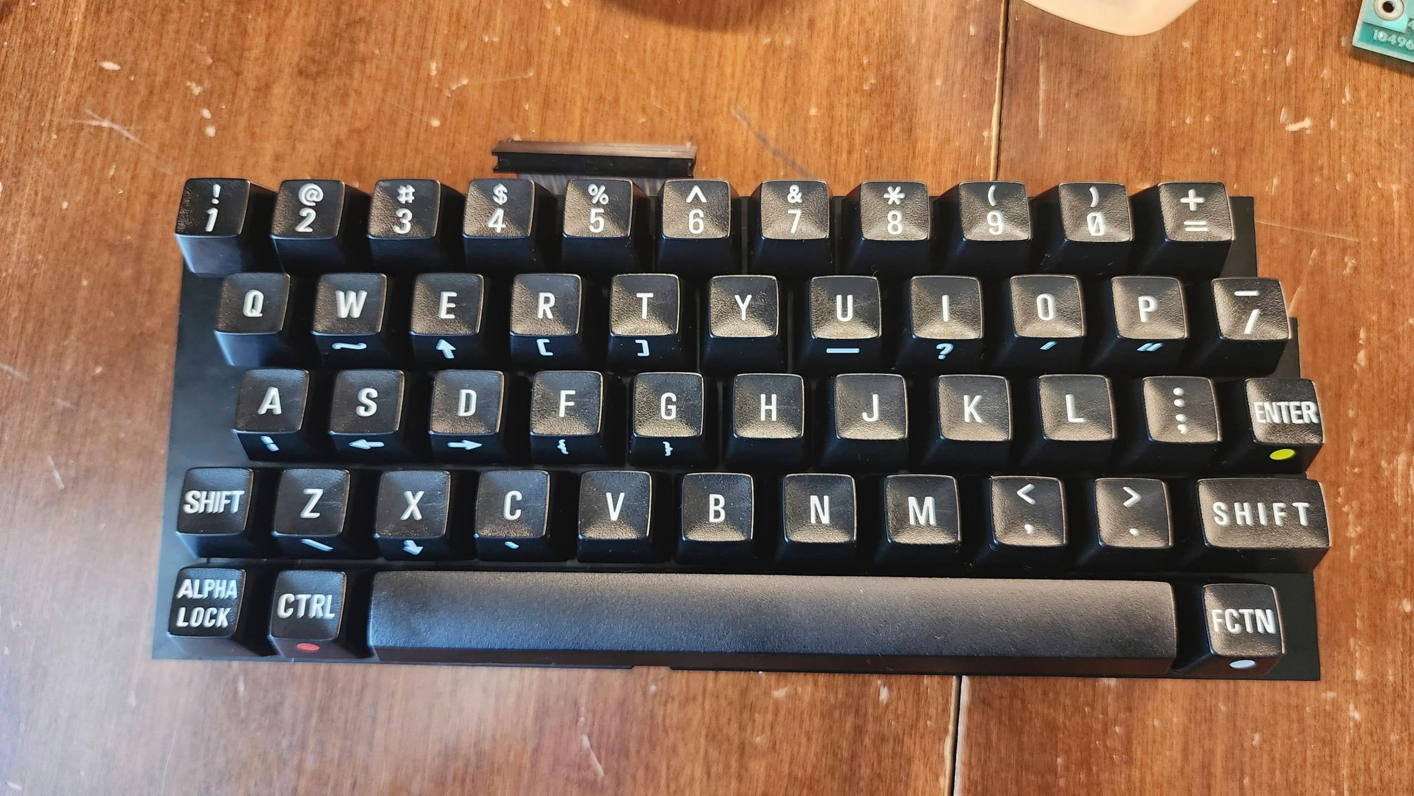
Interesting Fact: The TI99/4A was the updated version of the TI99/4 that was originally released in 1979. (source) The original TI99/4 was unique in that it was the first 16-bit home computer to reach the market, but unfortunately, its architecture limited the machine to being merely 8-bit in functionality. (source) The TI99/4 suffered from poor sales, and so the TI99/4A was released in 1981 as a more competitive replacement. (source) Unfortunately, the basic architecture of the 4A remained the same as its predecessor with the main upgrades being a better keyboard and the TMS9918A Video Display Processor (VDP). (source) Approximately 2.8 million TI99/4As were sold during its production run. (source)
Condition When Acquired: Non-Functional
Current Condition: Fully Functional


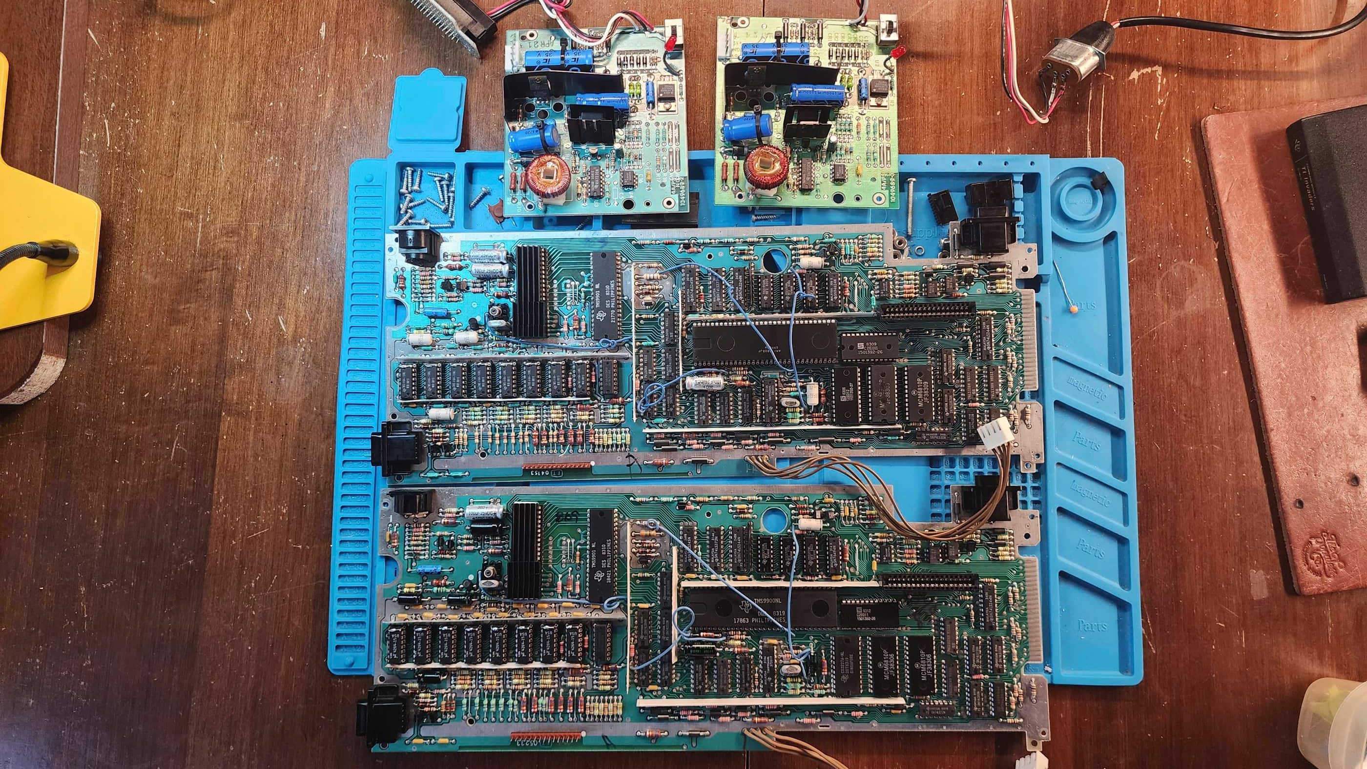
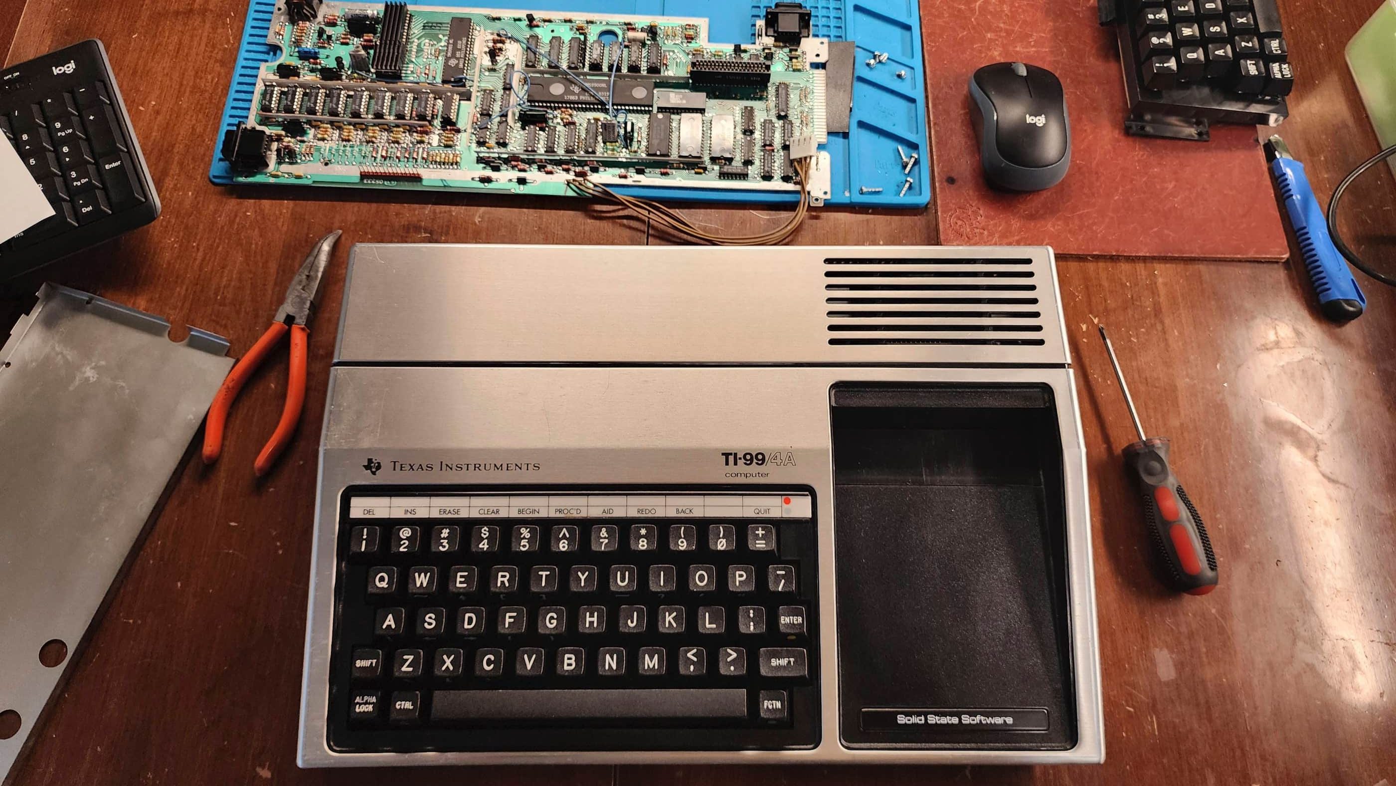


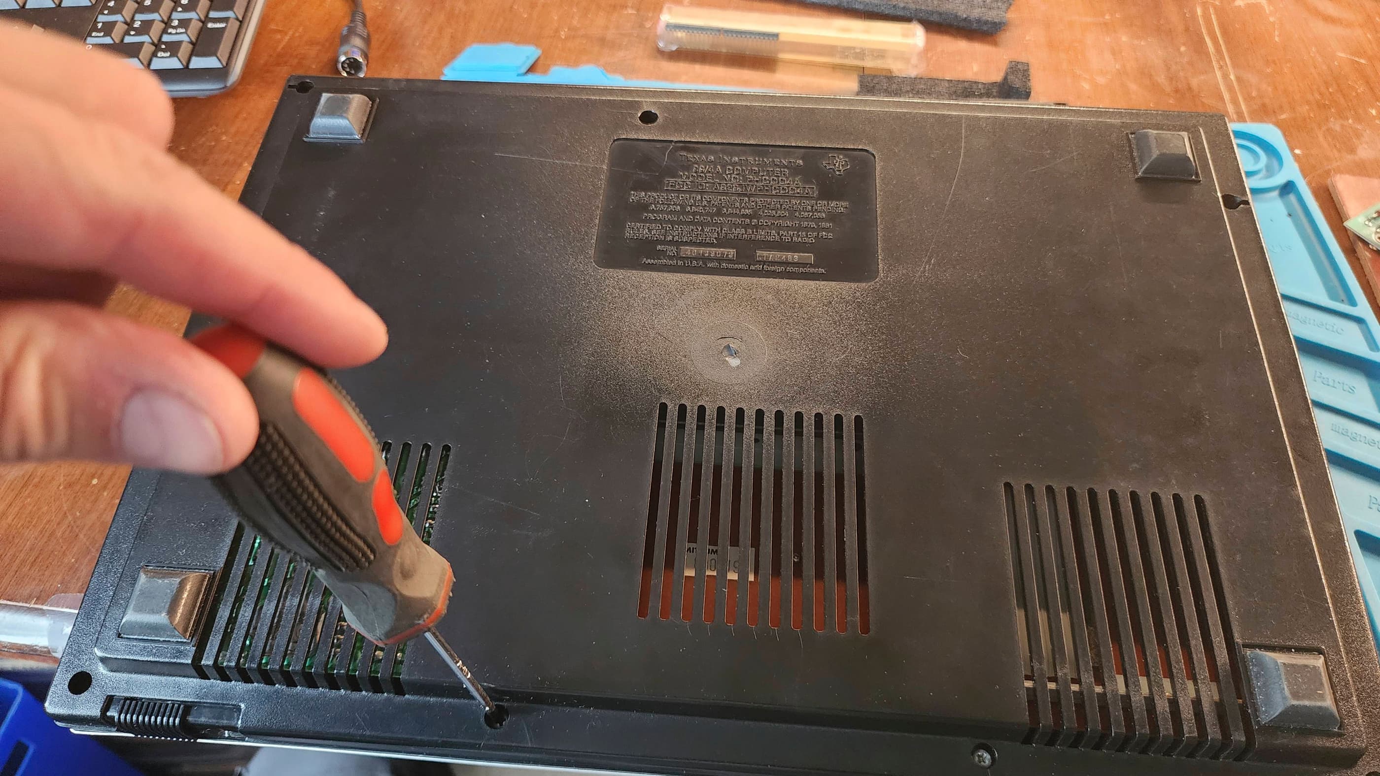
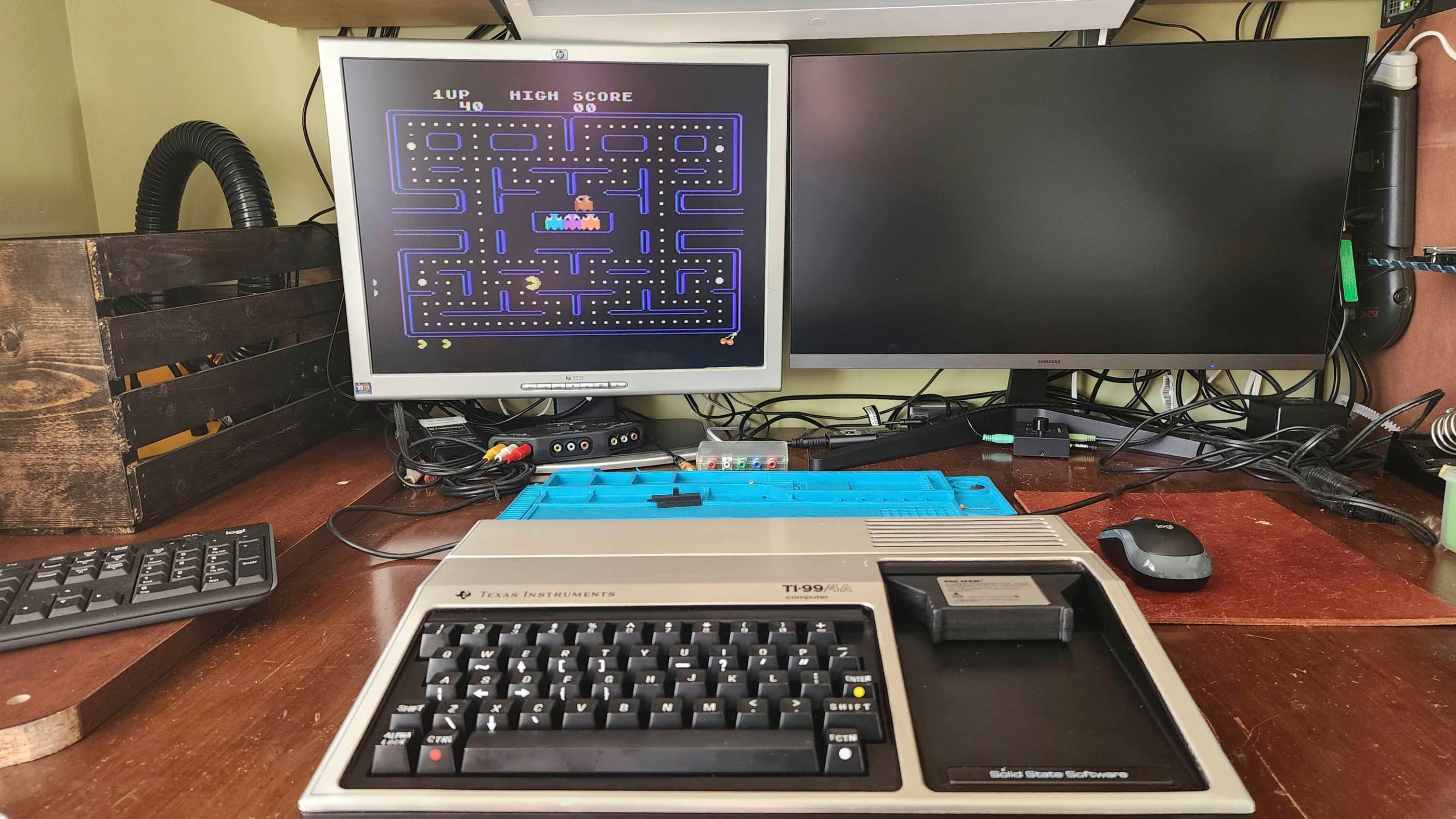
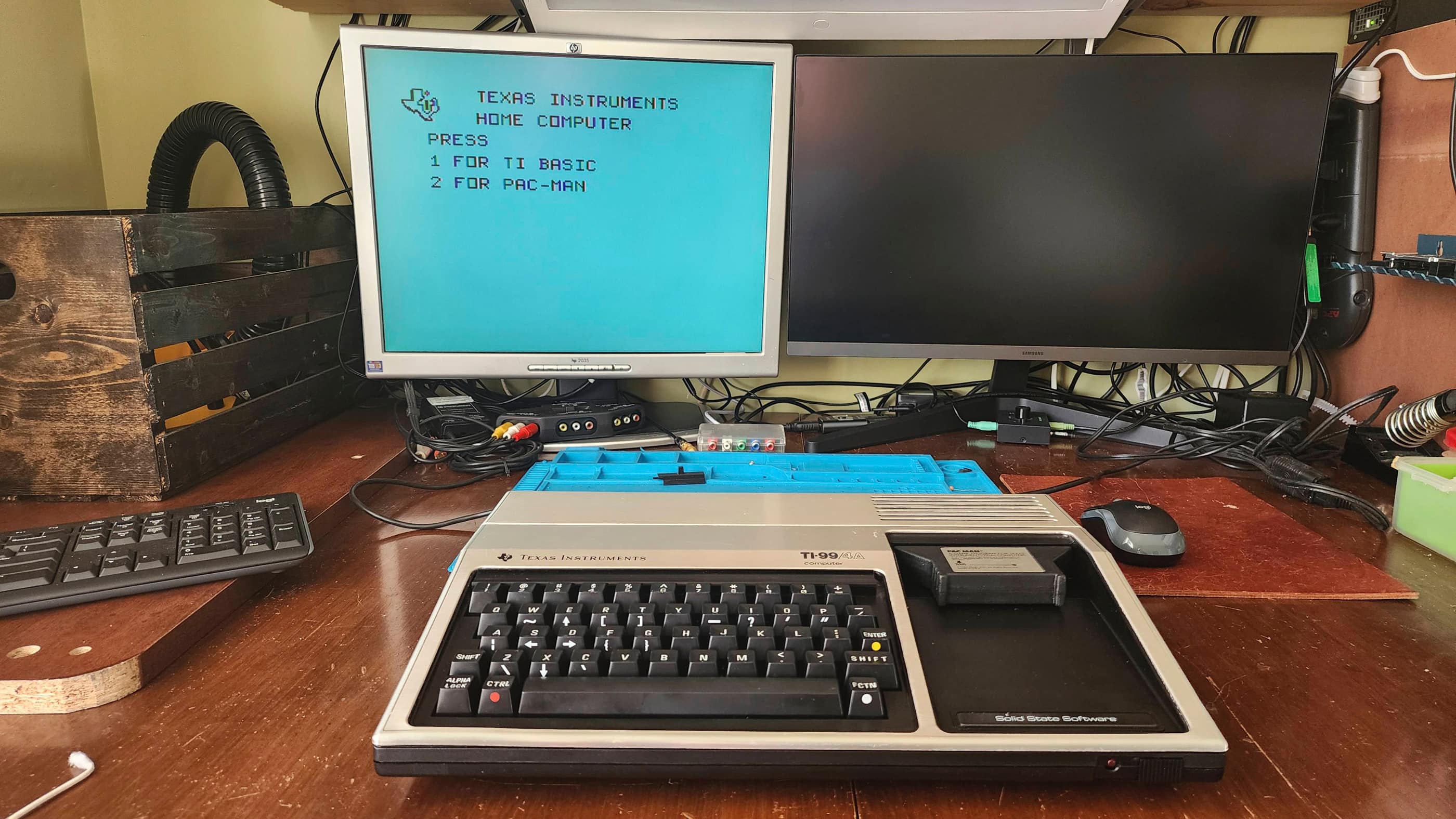
Project Details: I acquired this machine and a second TI99/4A at almost the same time, so it was helpful to work on both concurrently. All I knew about this particular machine, was that the power light came on when it was plugged in, but it was never connected to a monitor or TV. Like many of my consoles and computers, it came to me as a mystery box.
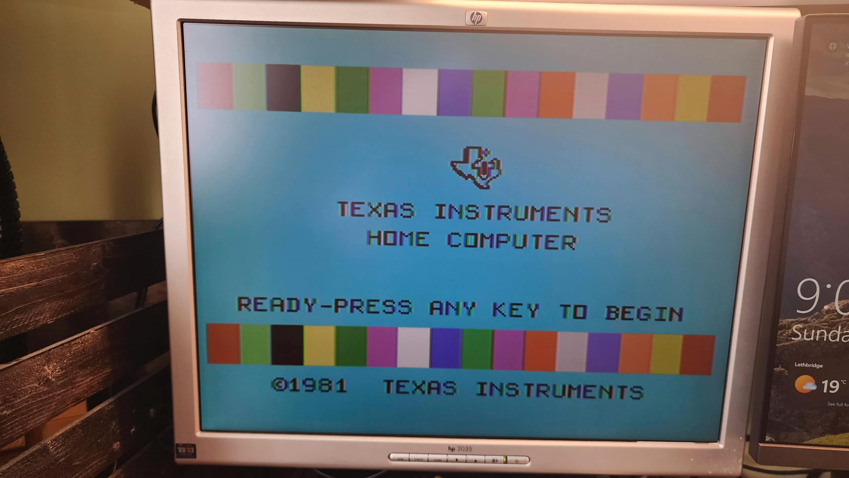
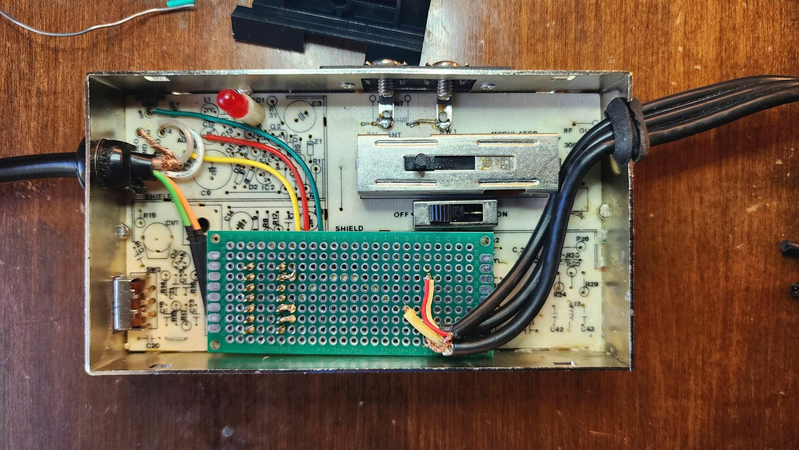
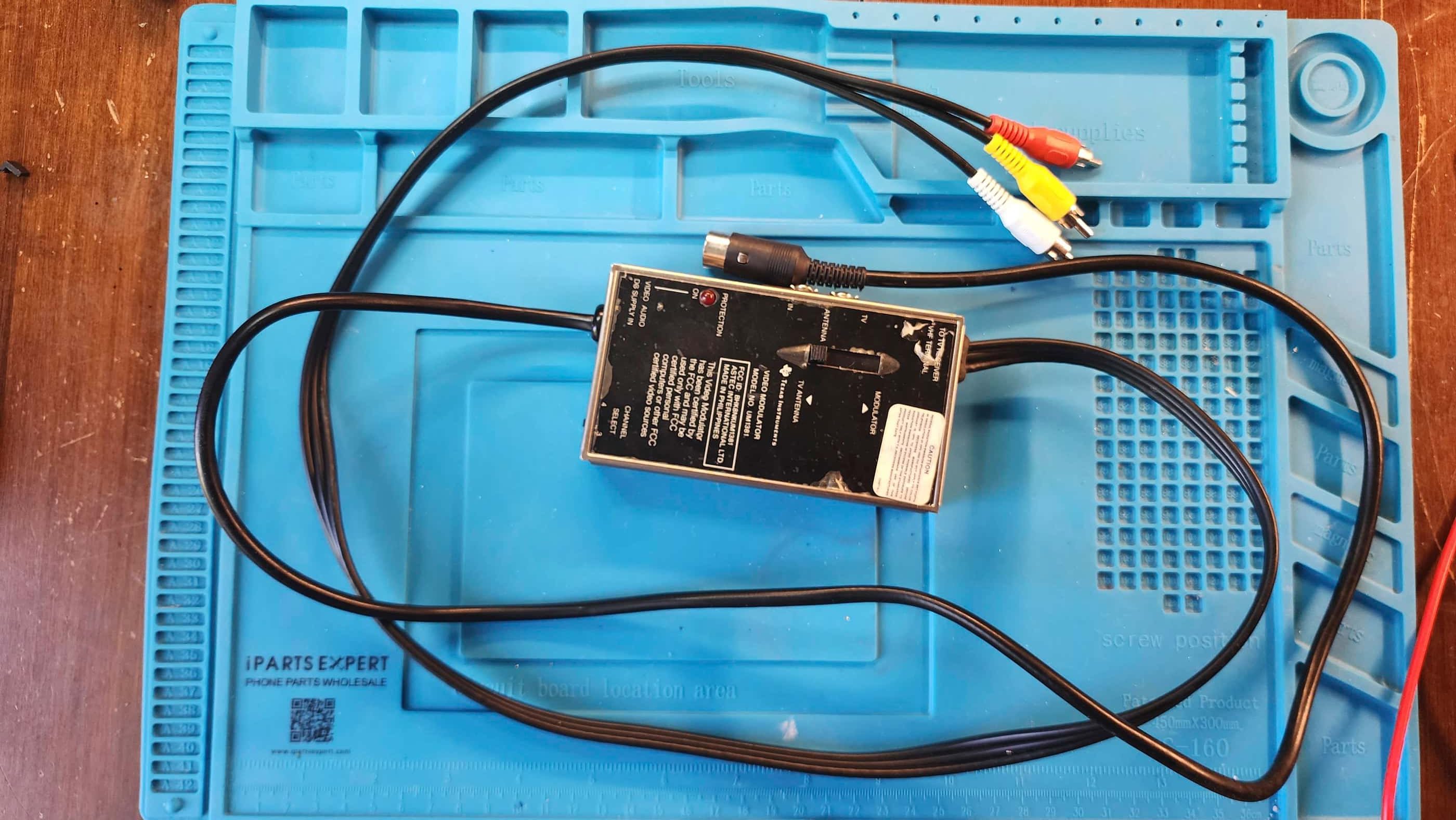
After removing it from its original box, my first step was to check the voltages coming from the external power adapter. Once I confirmed that they were in spec, I hooked the TI99/4A up to the RF input on my TV and turned the computer on. I was promptly greeted with a black screen and a continuous high-pitched sound. 😳
This prompted me to consult the Elders of the Internet and I was particularly grateful to Adrian Black from Adrian’s Digital Basement and also Noel from Noel’s Retro Lab for their TI99/4A repair videos. However, like both Adrian and Noel, diagnosing the precipitating fault for the black screen was a bit of an adventure.
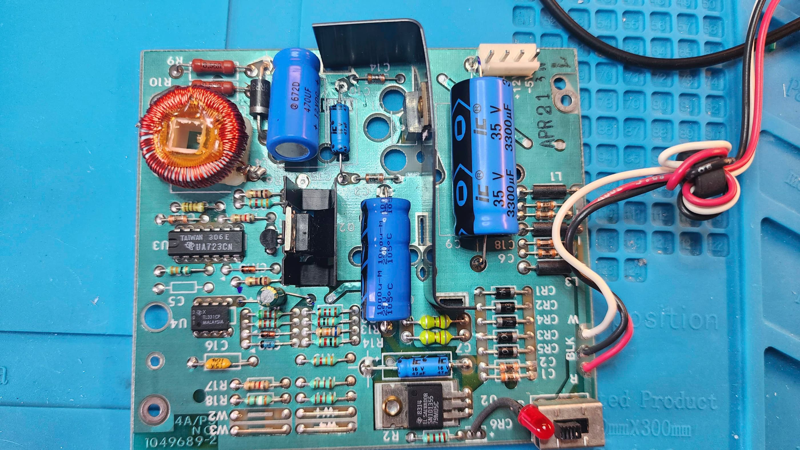
My first theory was that it may have had something to do with the proprietary RF connector; however, using a known working cable ruled that out. Next, I disassembled the computer and began voltage testing the internal power board and elsewhere on the main board. The voltages were normal, but a couple caps on the power board had weird, burn-like patterns, so I replaced these. However, the unit still presented a black screen with a continuous high-pitched sound.
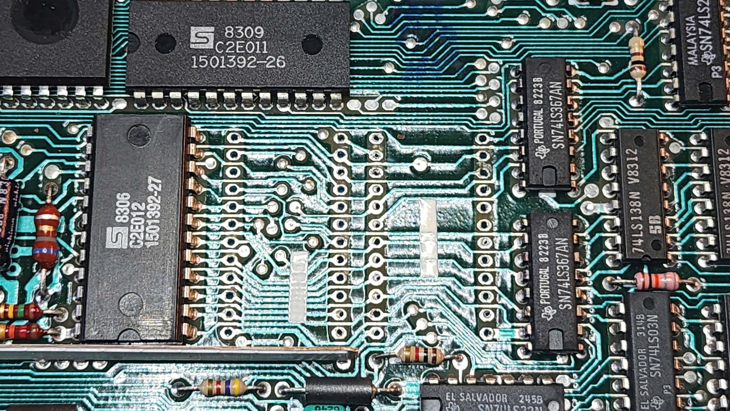
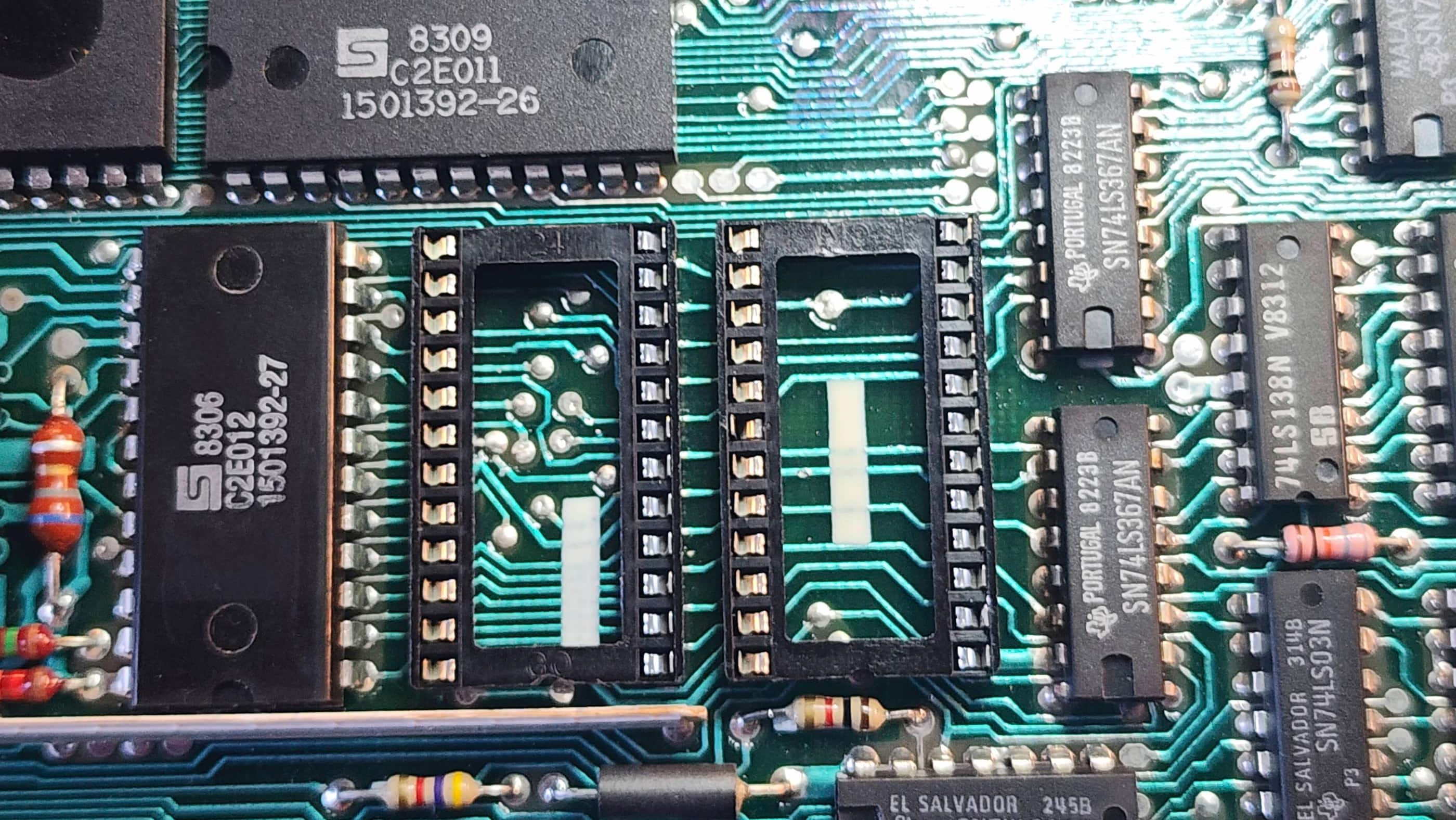
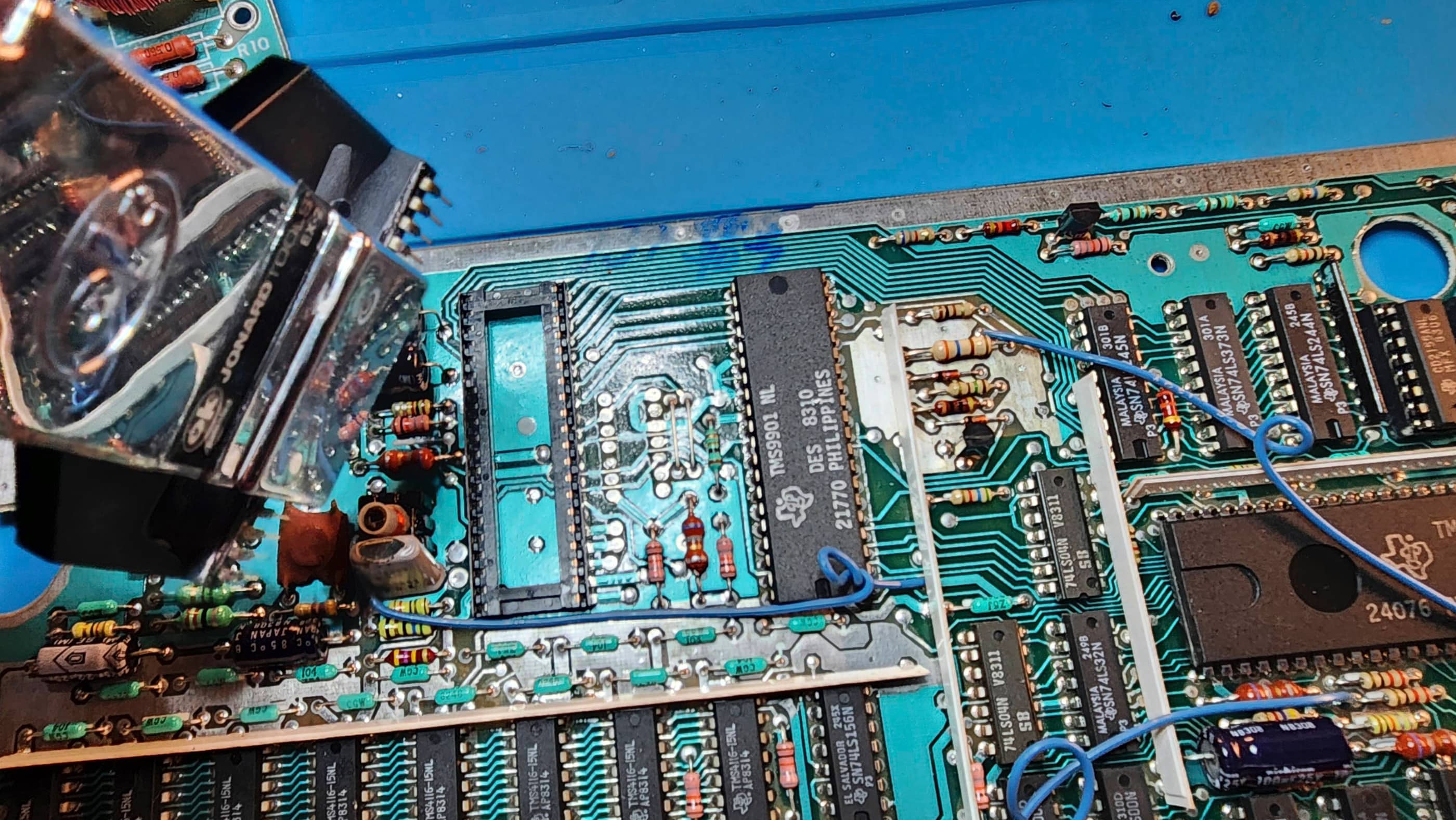
I then downloaded the original TI99/4A Data Sheet and the super helpful, Sams TI99/4A Computerfacts Technical Service Data booklet. Both of these links I found on the relevant Atari Age forum. Before doing further in-depth probing, I reseated all of the socketed chips and I swapped the VDP with my other TI99/4A – which is where I discovered that the VDP from this computer was good and that the VDP (U100) from my second computer was bad – so it pays to work on two boards concurrently. 🙂
From all of the aforementioned technical information, I deduced that the problem lay in the first 5 steps of the start-up sequence; resulting in the sound chip not shutting off from its initial singular beep.
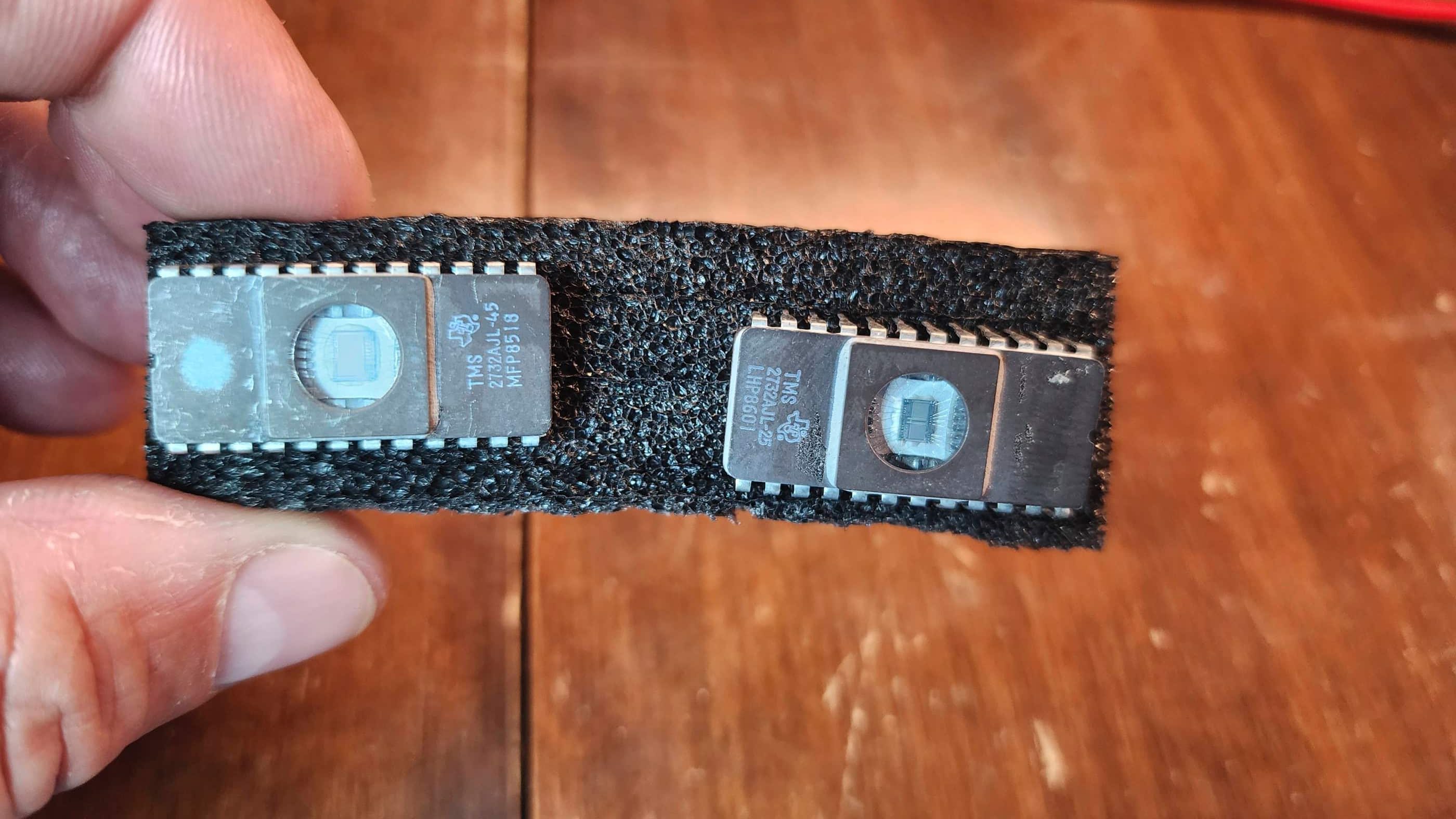
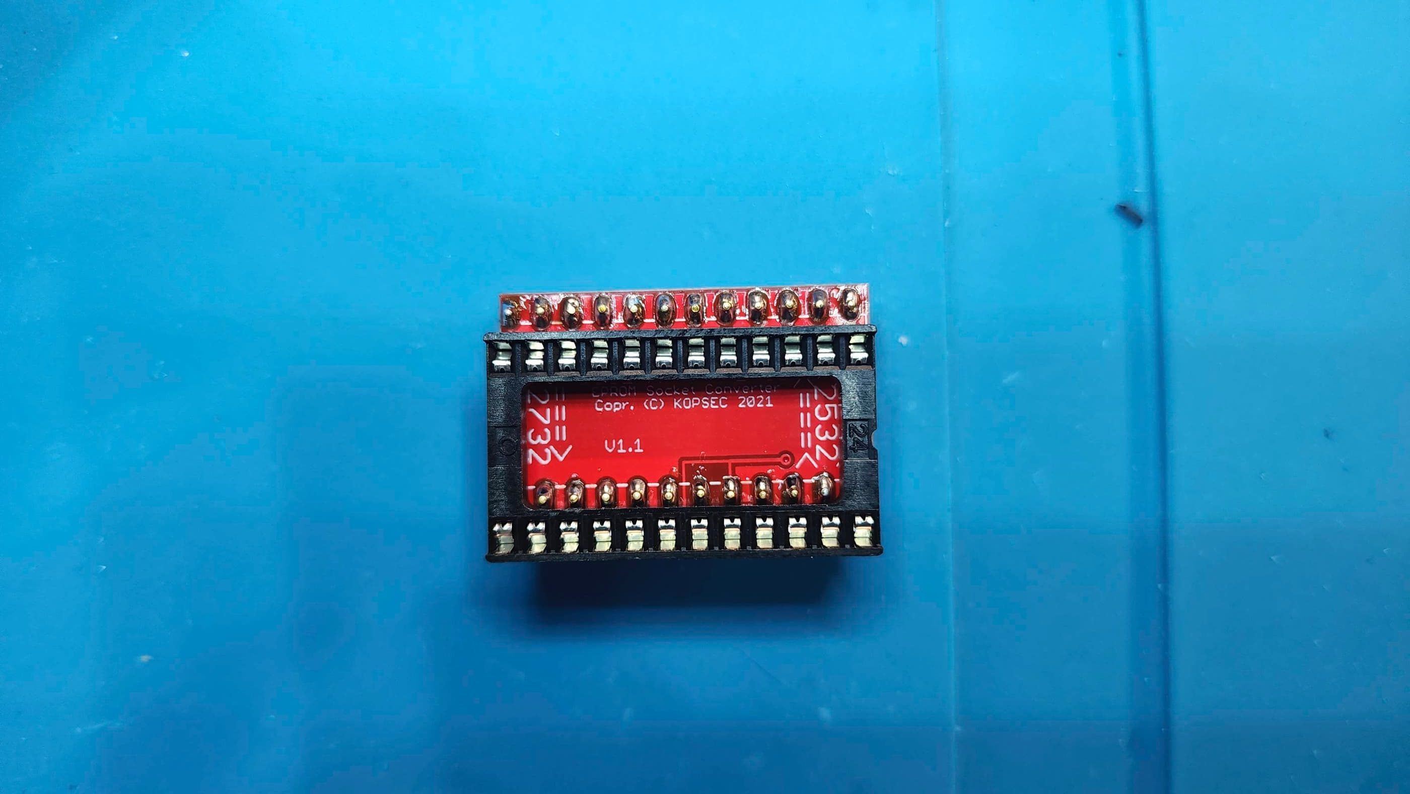
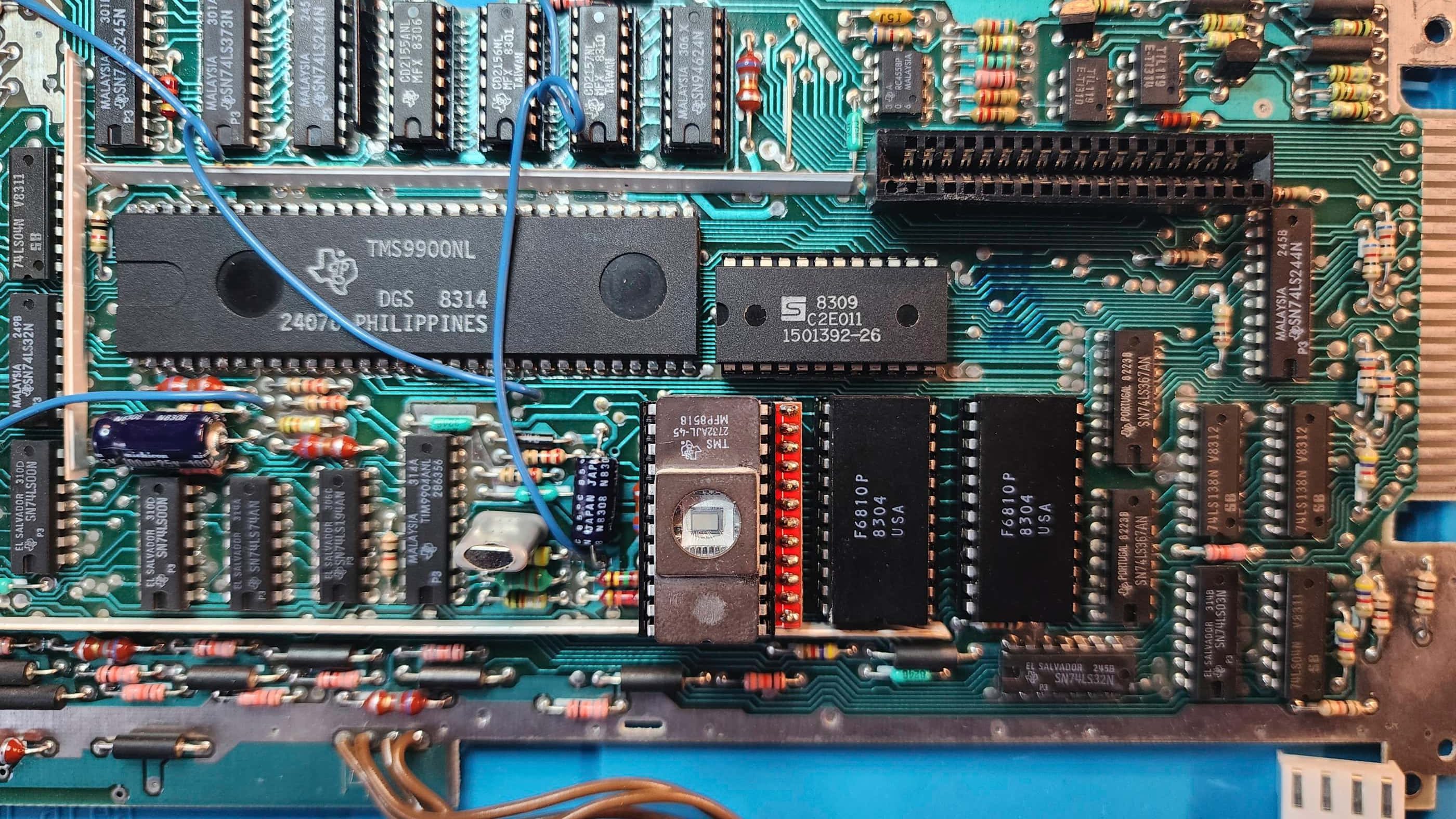
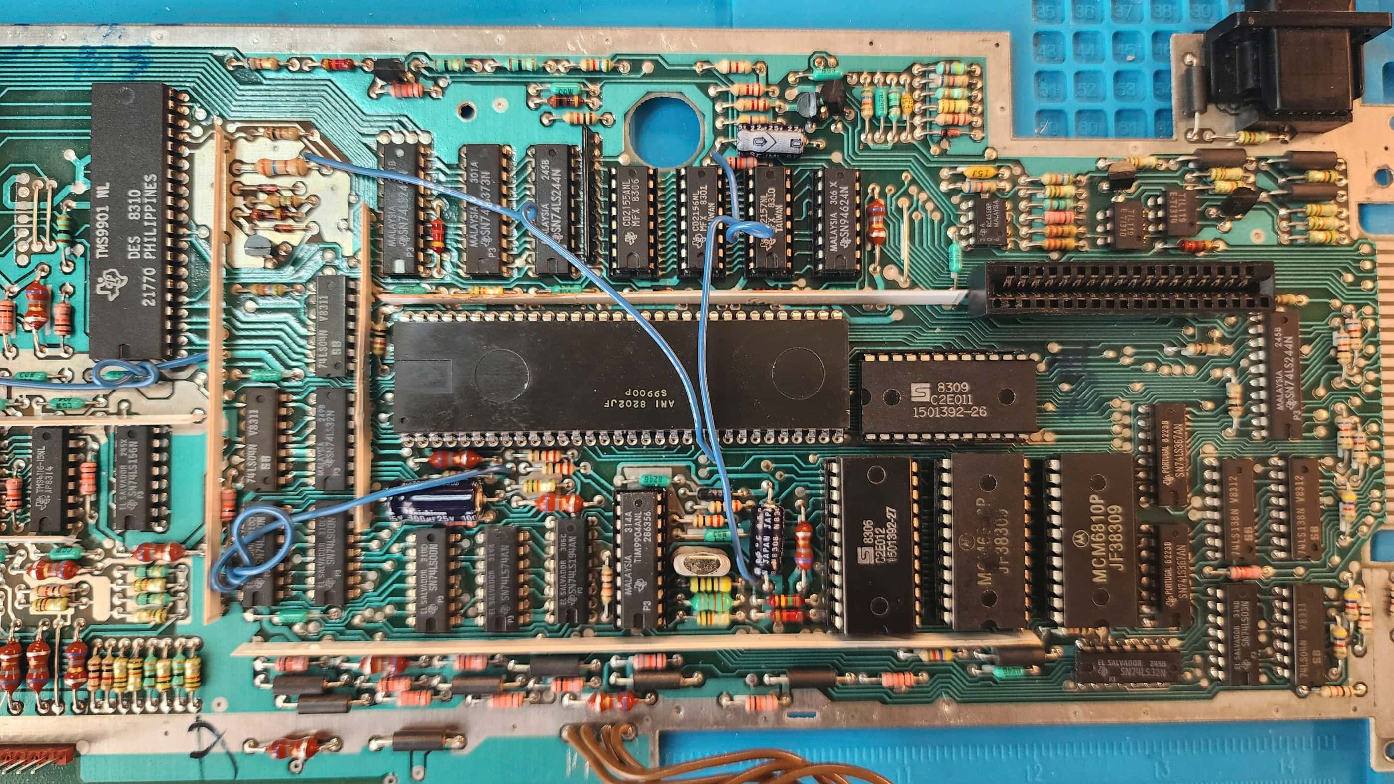
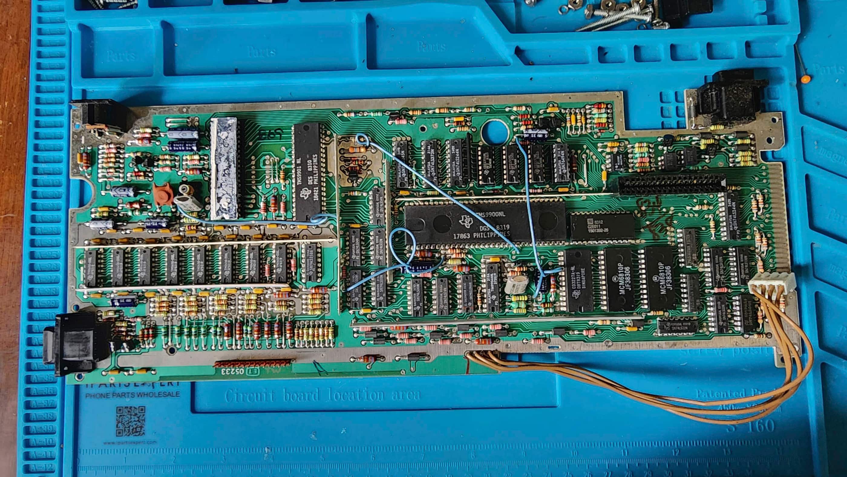
This is where the real adventure began, and in the subsequent diagnosis, I ended up: removing and replacing the SRAM (U609 & U608); programming and replacing the ROMs (U610 & U611); and replacing the clock generator (U601) even though all four clocks tested normal.
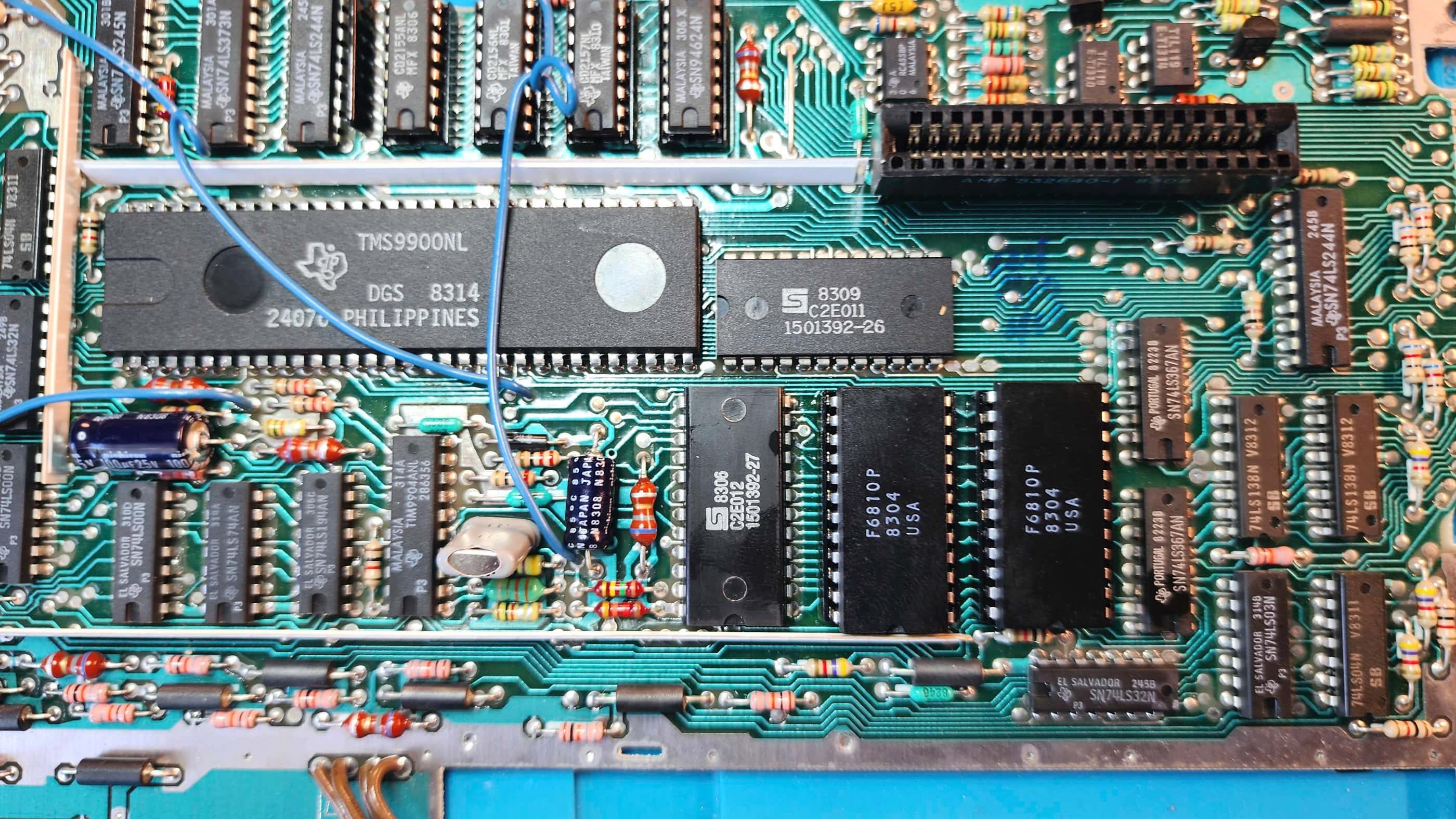
I then turned my attention to the CPU (U600) and had I checked this first with a logic probe early on, I would have discovered some irregularities based on what the service manuals indicated were normal signals. However, my oscilloscope missed these or more accurately, I missed these while using the scope and this is why I was stumped. Once I’d ruled out everything else, including swapping the GROMs with the other system, I returned to the CPU.
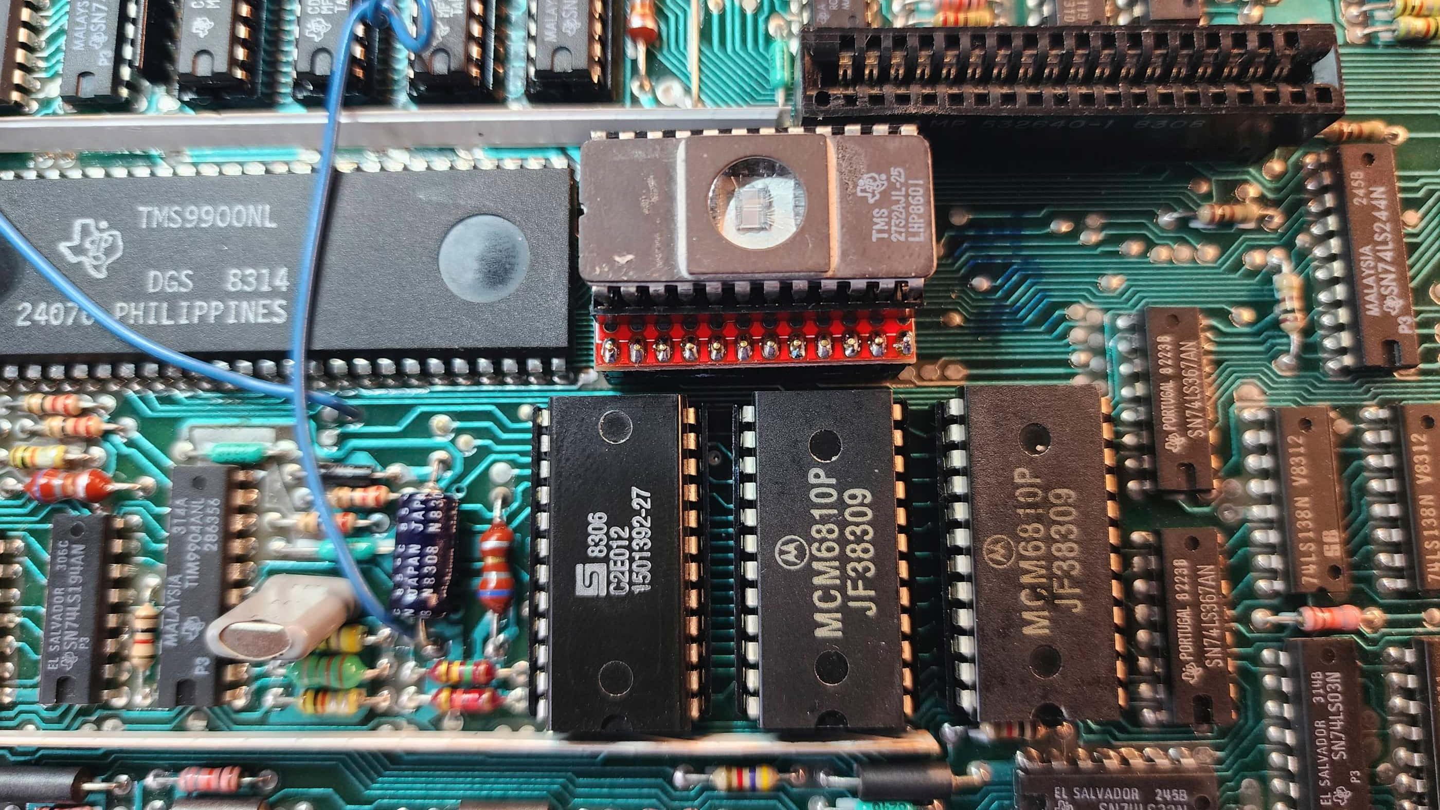
After carefully de-soldering all 64 pins of the chip, I removed it and soldered in a socket (I also added sockets to the other chips that I removed). When my replacement CPU arrived (I used an AMI S9900P which is the equivalent to the original TMS9900), I powered up the machine and it worked! Success!! 😁
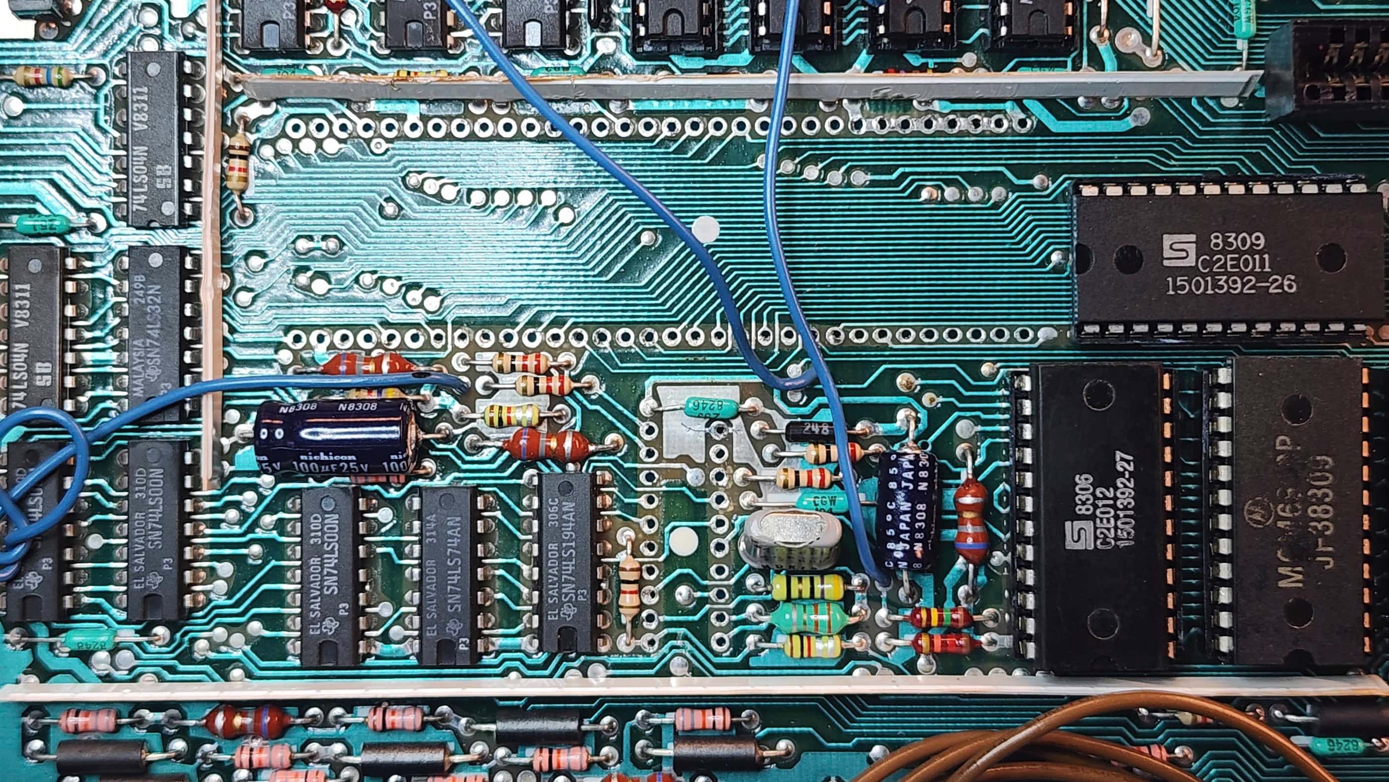
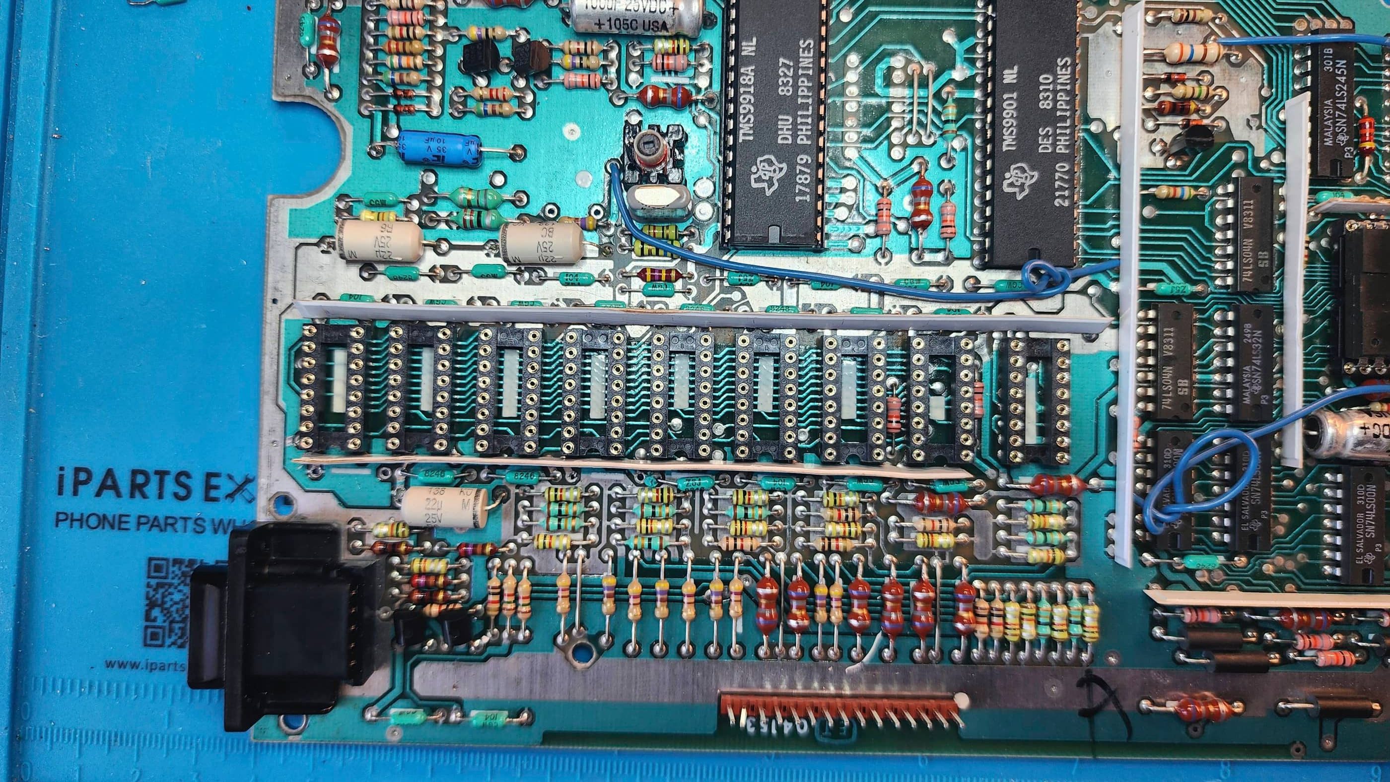
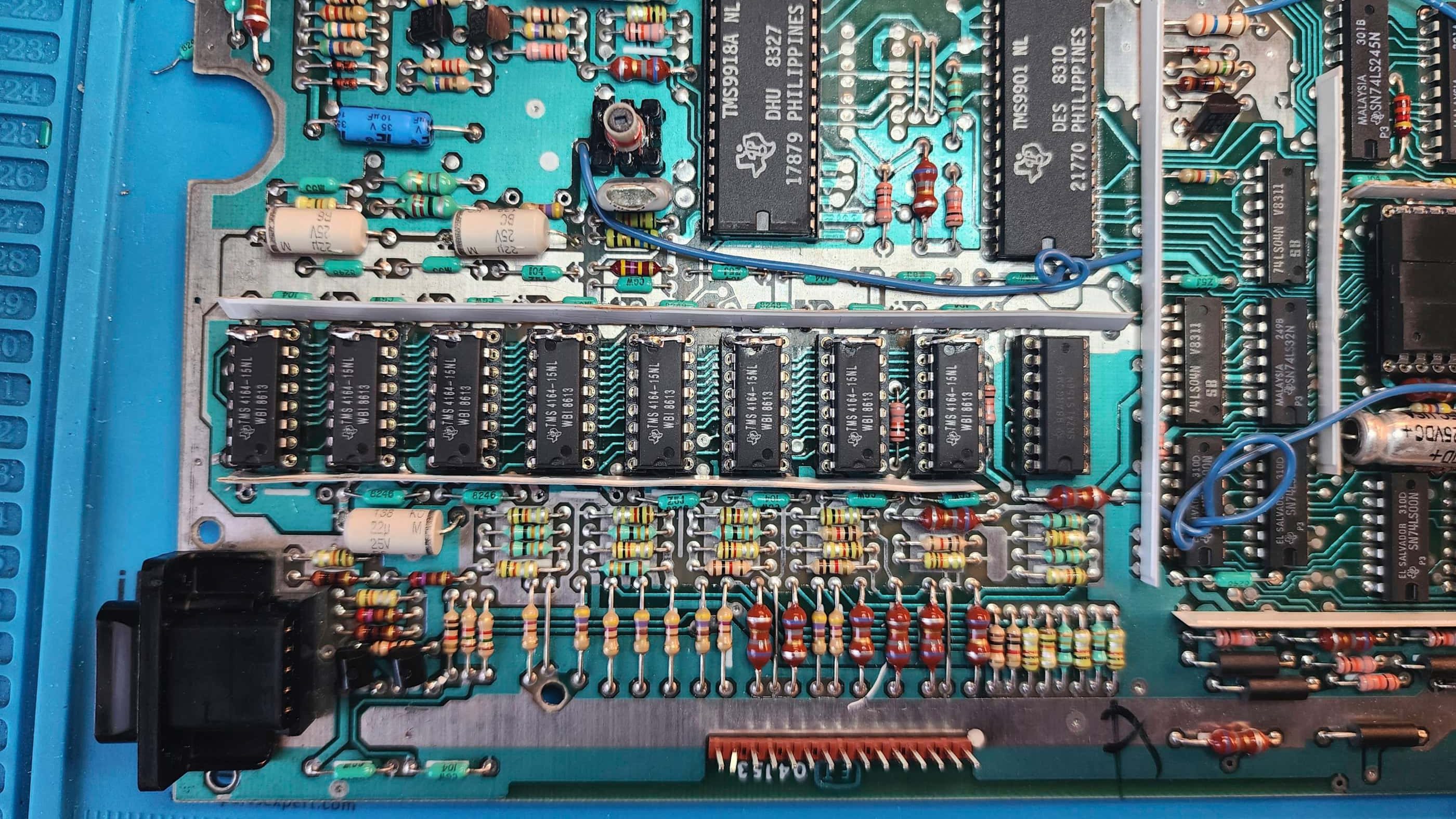
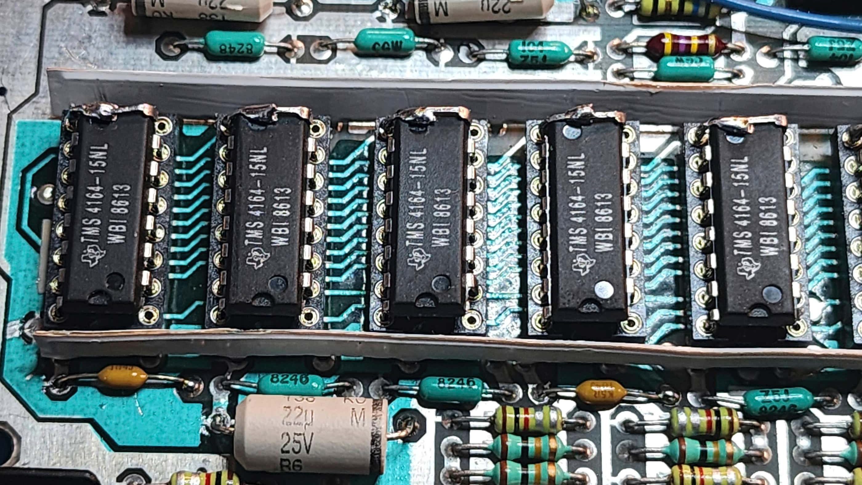
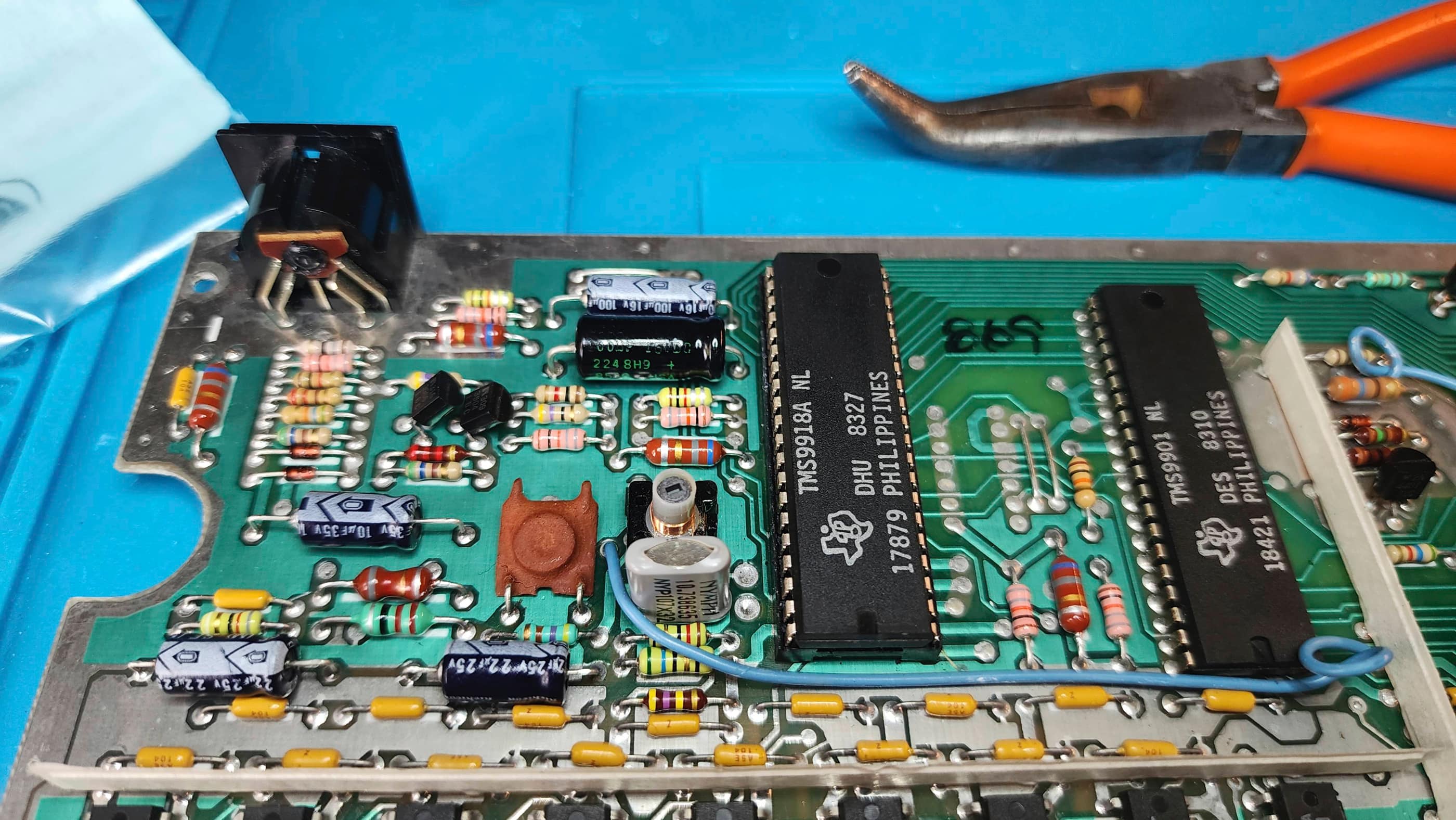
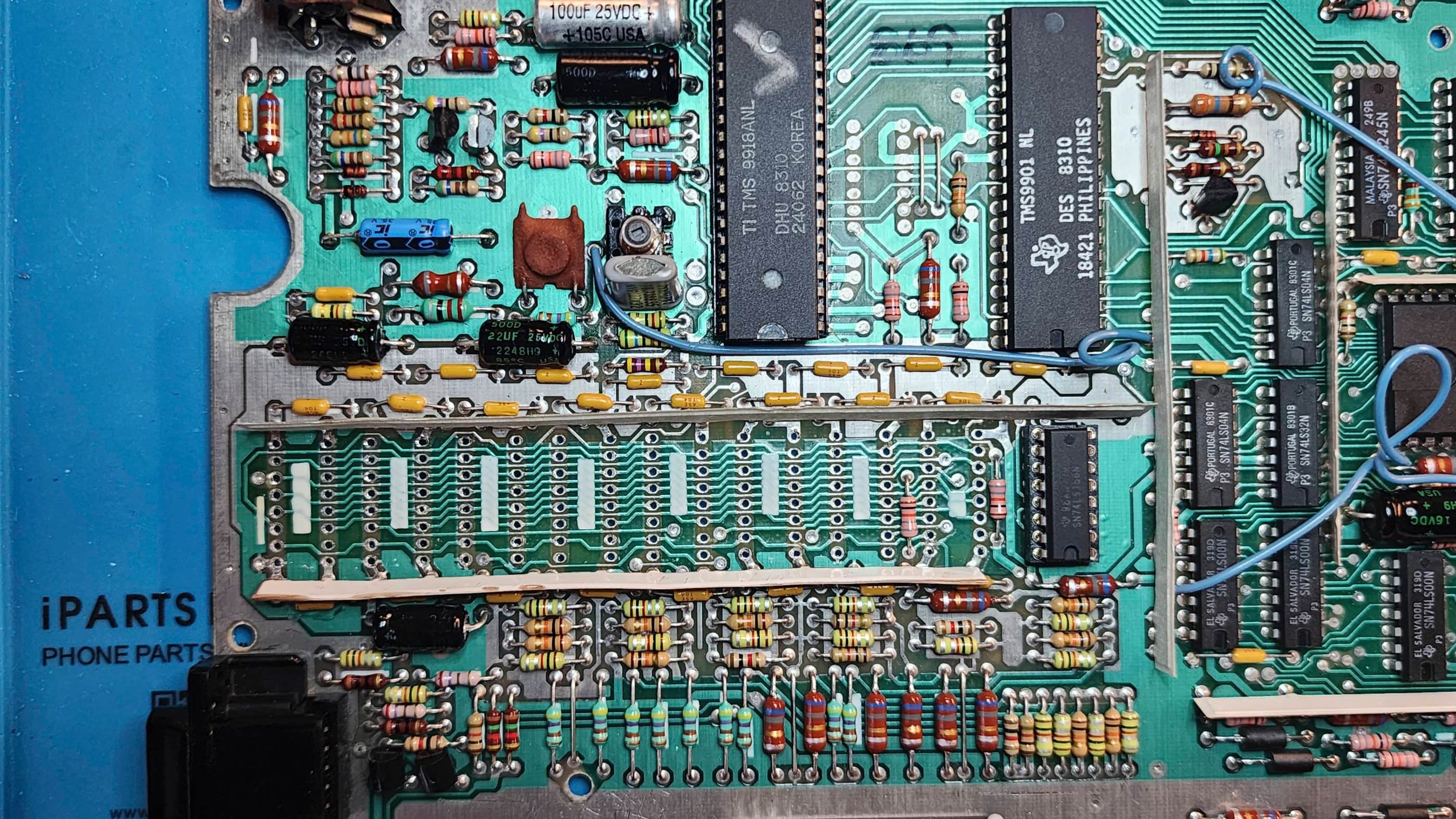
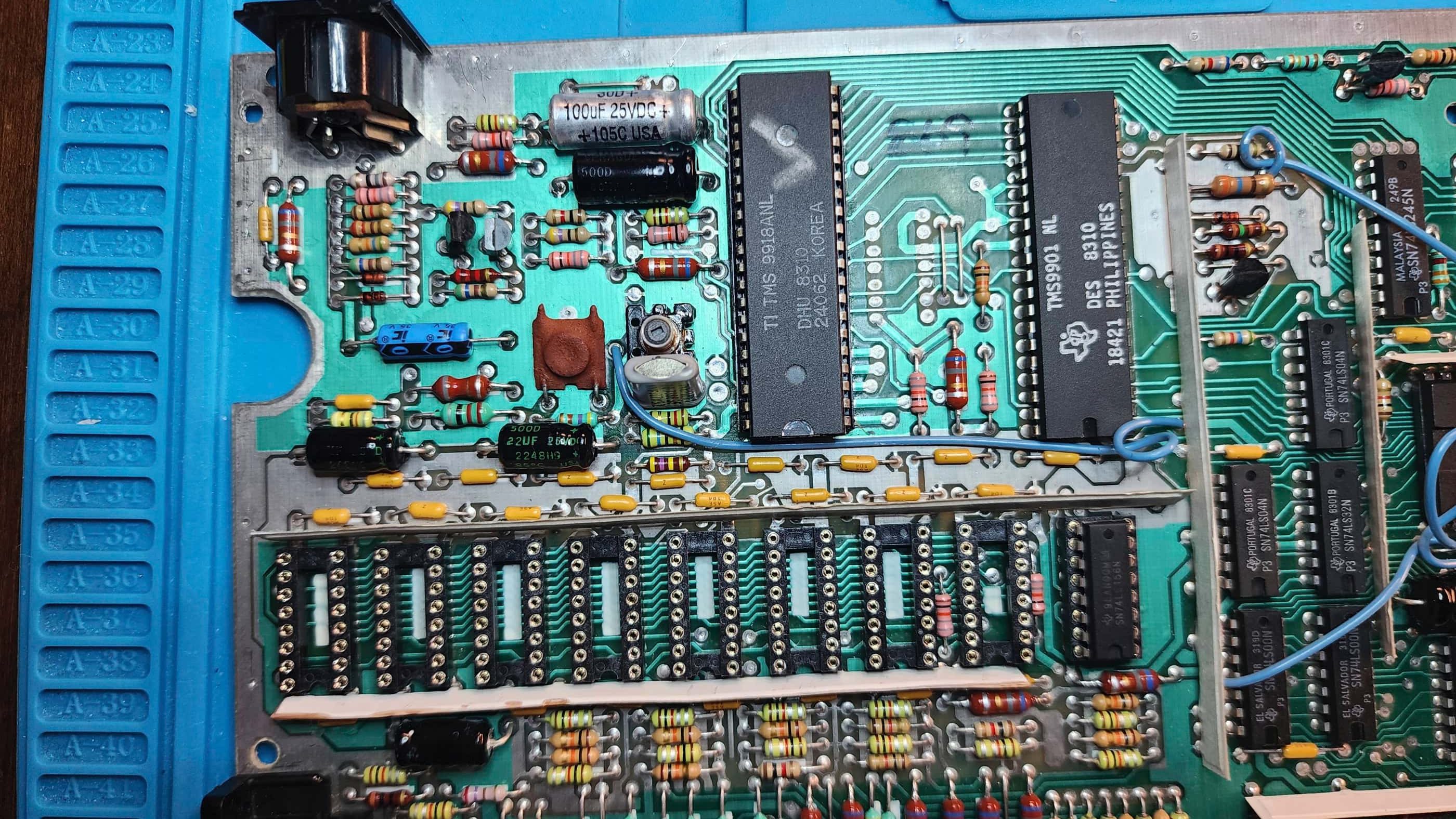
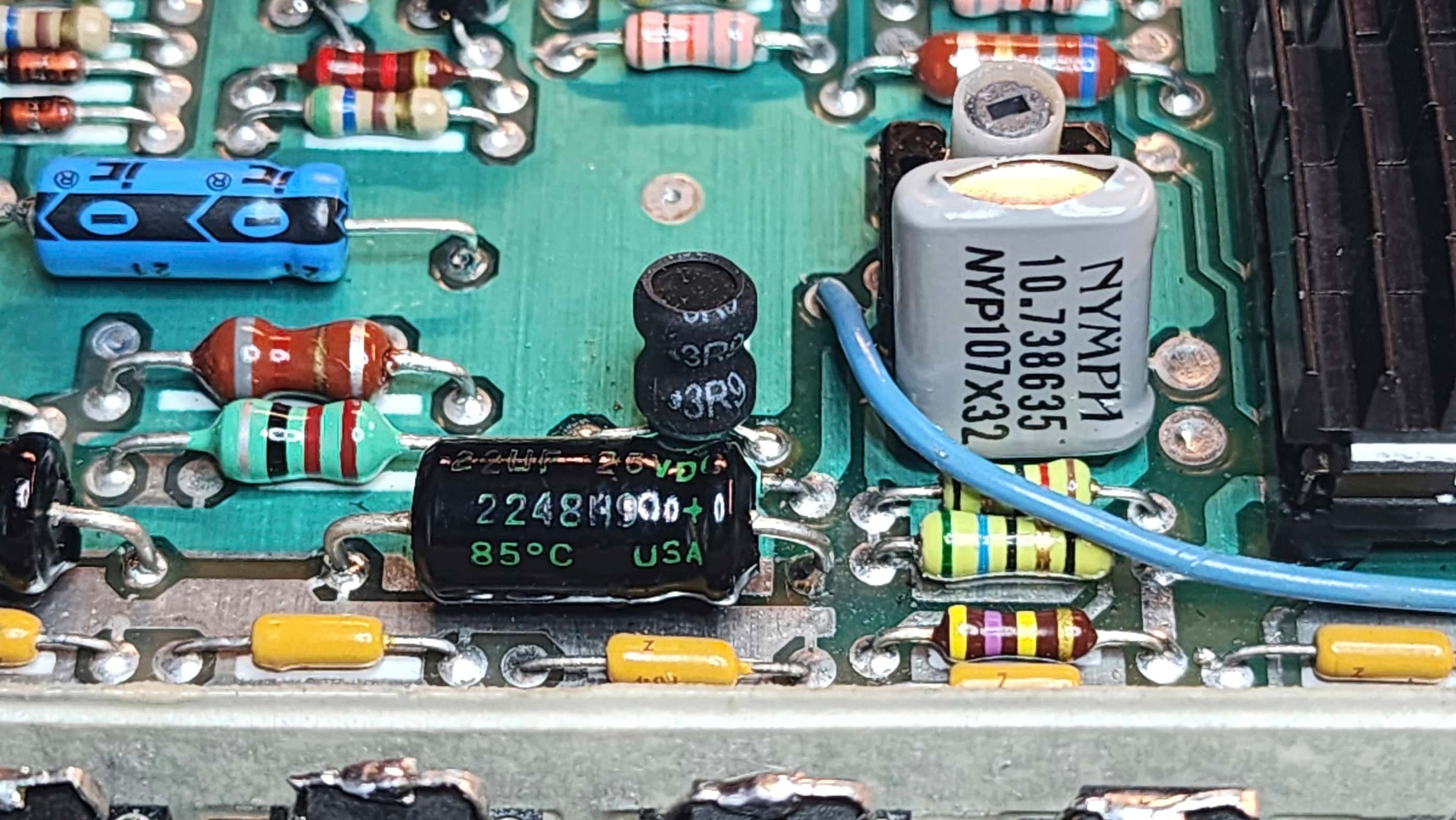
Now that everything was working, I proceeded to make some future-proofing mods. First, I finished re-capping the rest of the power board followed by replacing all of the caps on the main board. I then turned my attention to the DRAM, where I noticed that a couple of the ceramic caps (C120 & C123) had bad cracks. I then made the decision to swap out the 4116 DRAM and replace it with modified and socketed 4264 DRAM to make the system run cooler by using less voltage. The SN74LS156N (U302) was also removed and replaced with a socketed brand-new replacement. In the process, I also replaced both of the cracked ceramic caps.
As I was working on my other TI99/4A at the same time – which I diagnosed to have a bad choke and a bad VDP – I went ahead and replaced the ceramic choke (L107 /L207) with a new 3.9UH 720MA replacement. I also added a new aluminum heatsink to the VDP (U100).
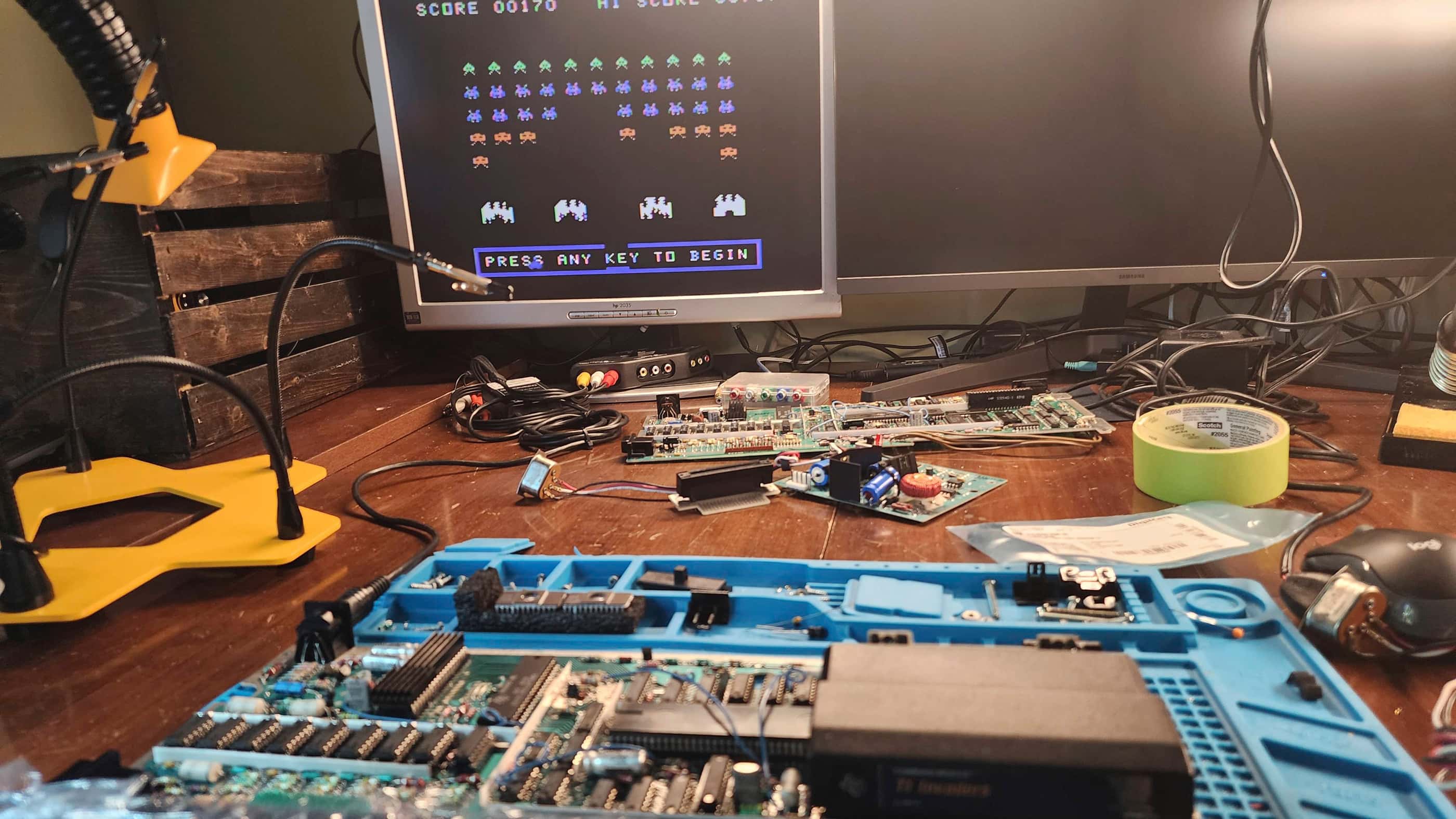
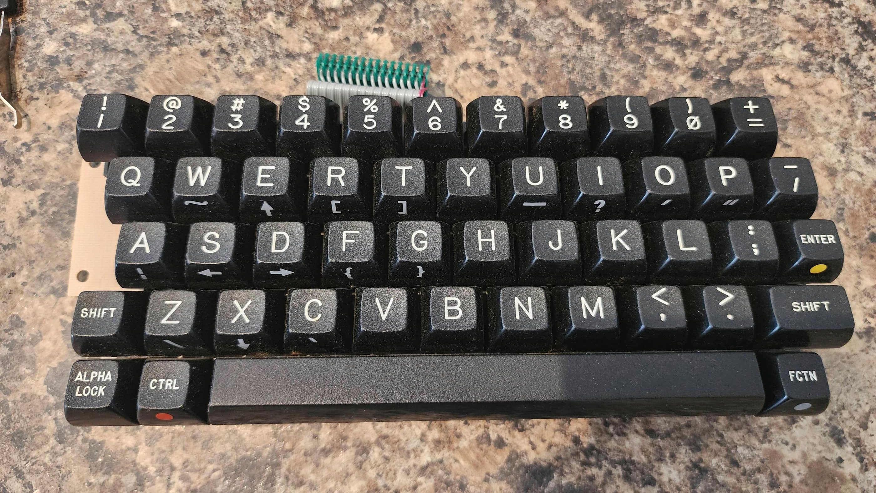
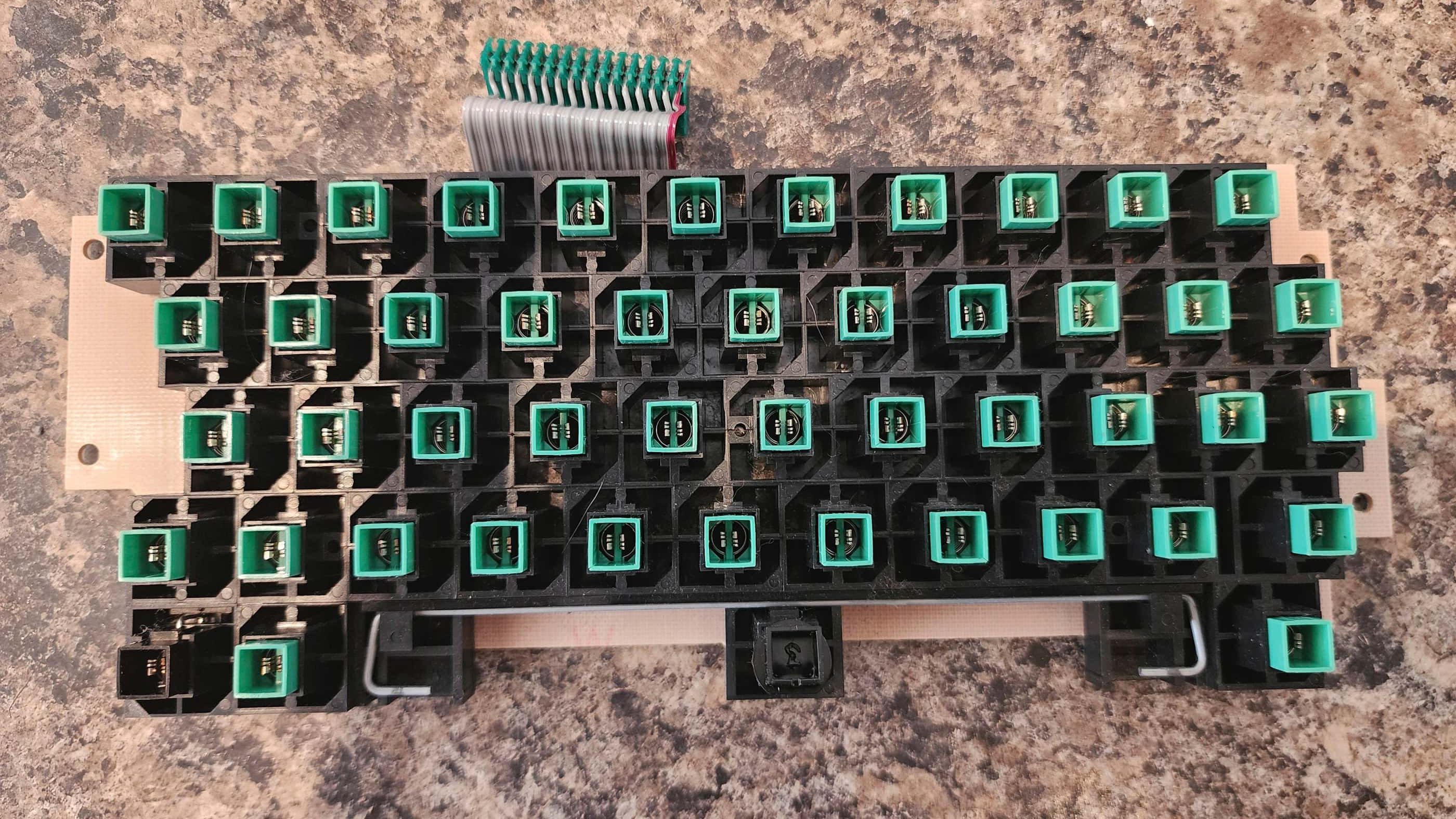
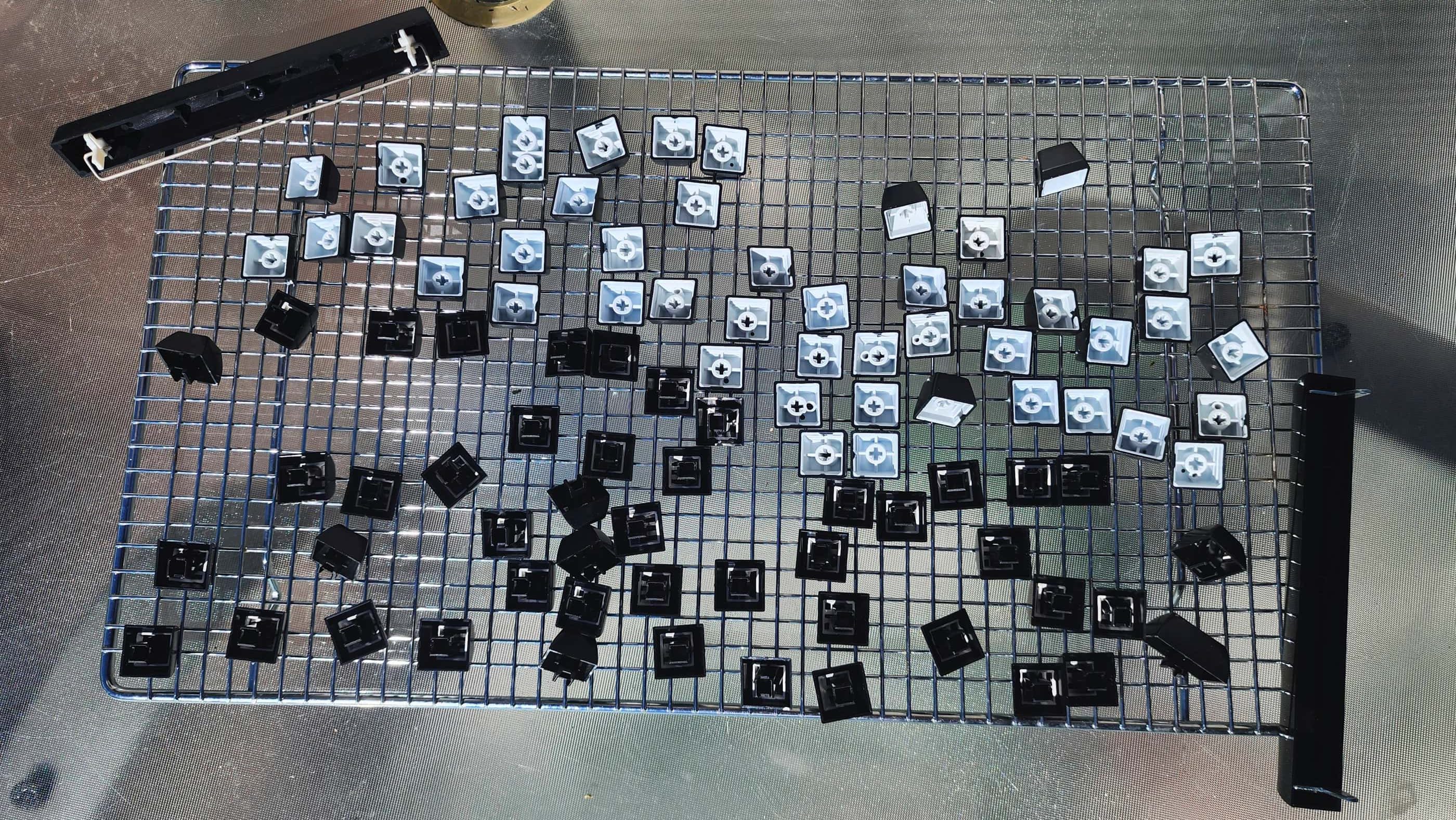
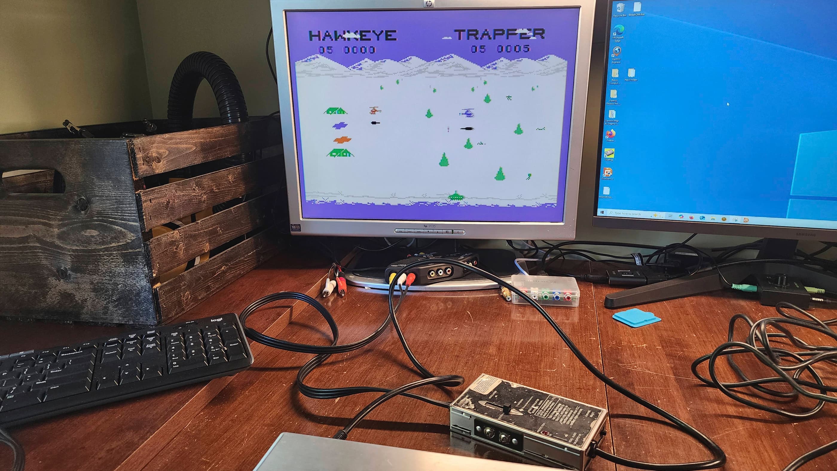
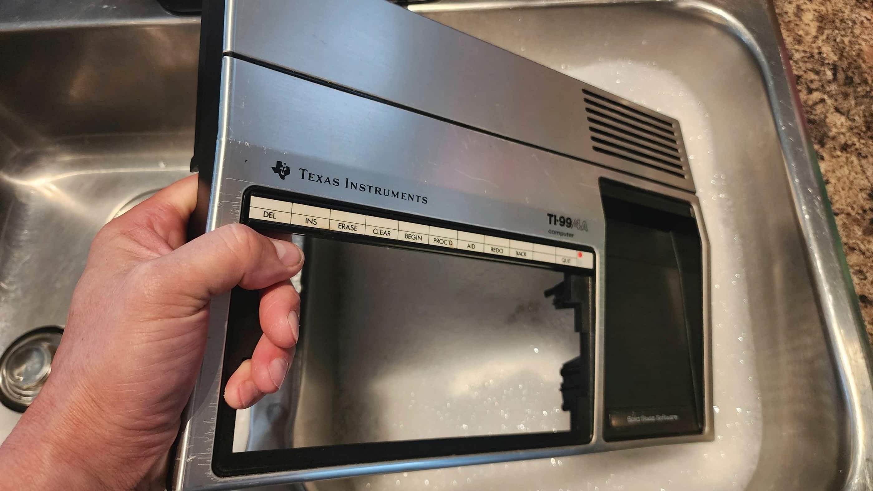
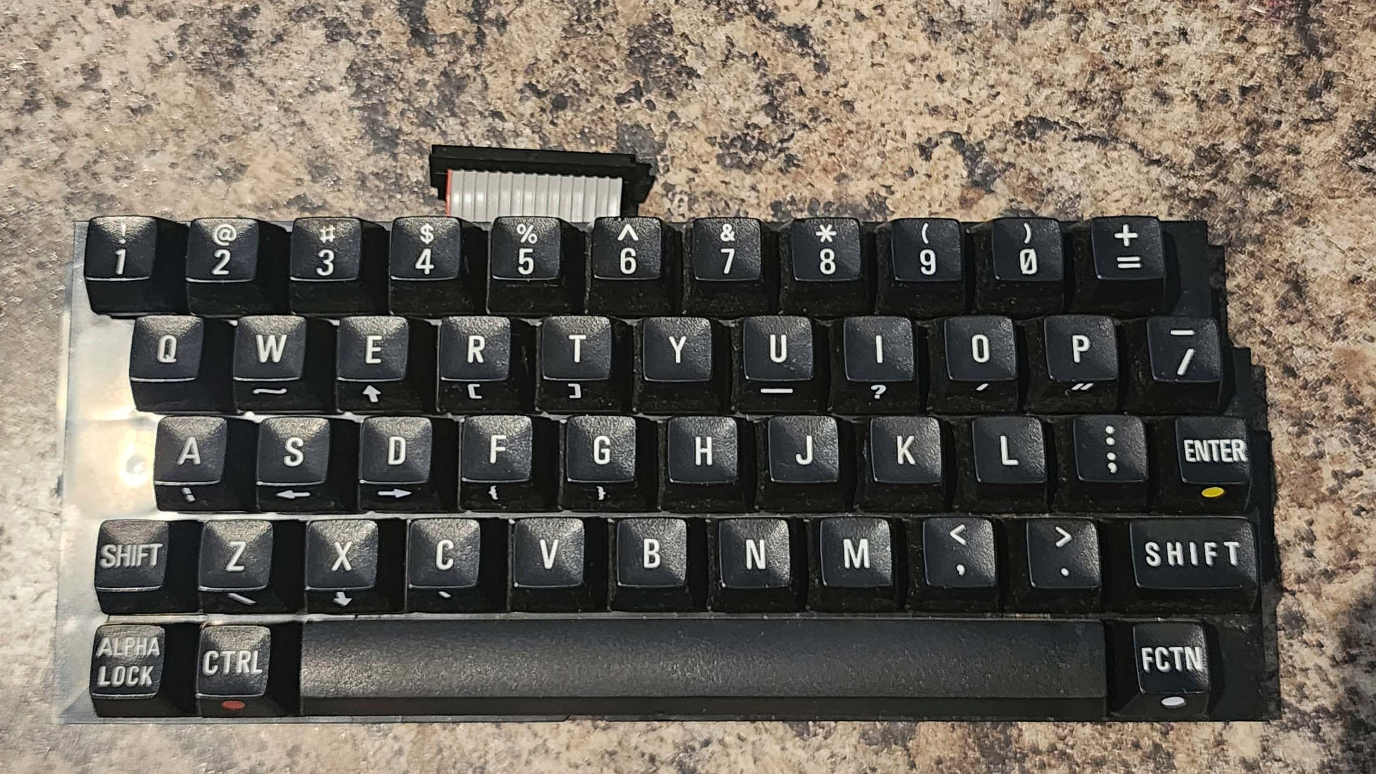
Finally, I cleaned the entire unit including the stackpole keyboard and then I tested the computer thoroughly. Everything was in great working order. 🙂
Parts and Products Used: 99% isopropyl alcohol; Chemical Guys Natural Shine; Deoxit D5; internal power board electrolytic capacitors (radial): 35v 4.7μF (1); internal power board electrolytic capacitors (axial): 12v 470 μF (1); 16v 47μF (2); 25v 1000μF (1); 35v 3300 μF (1); Main Board electrolytic capacitors (axial): 25v 10μF (1); 25v 22μF (5); 25v 100μF (3); L107/L207 choke replacement: 3.9μH 720MA (1); CPU: AMI S9900P; Clock IC: TIM9904ANL (1); DRAM: TMS 4146-15NL (8) – modified by removing PIN 1 and then bending and extending PIN 8 to join PIN 9; Multiplexer IC: SN74LS156N (1); IC Sockets: 14 PIN DIP machine pin (9); 20 PIN DIP double wipe (1); 24 PIN DIP double wipe (4); 64 PIN DIP machine pin (1); Aluminum heatsinks; double-sided thermal IC tape
Texas Instruments TI99/4A #2
Years (1981-1984)
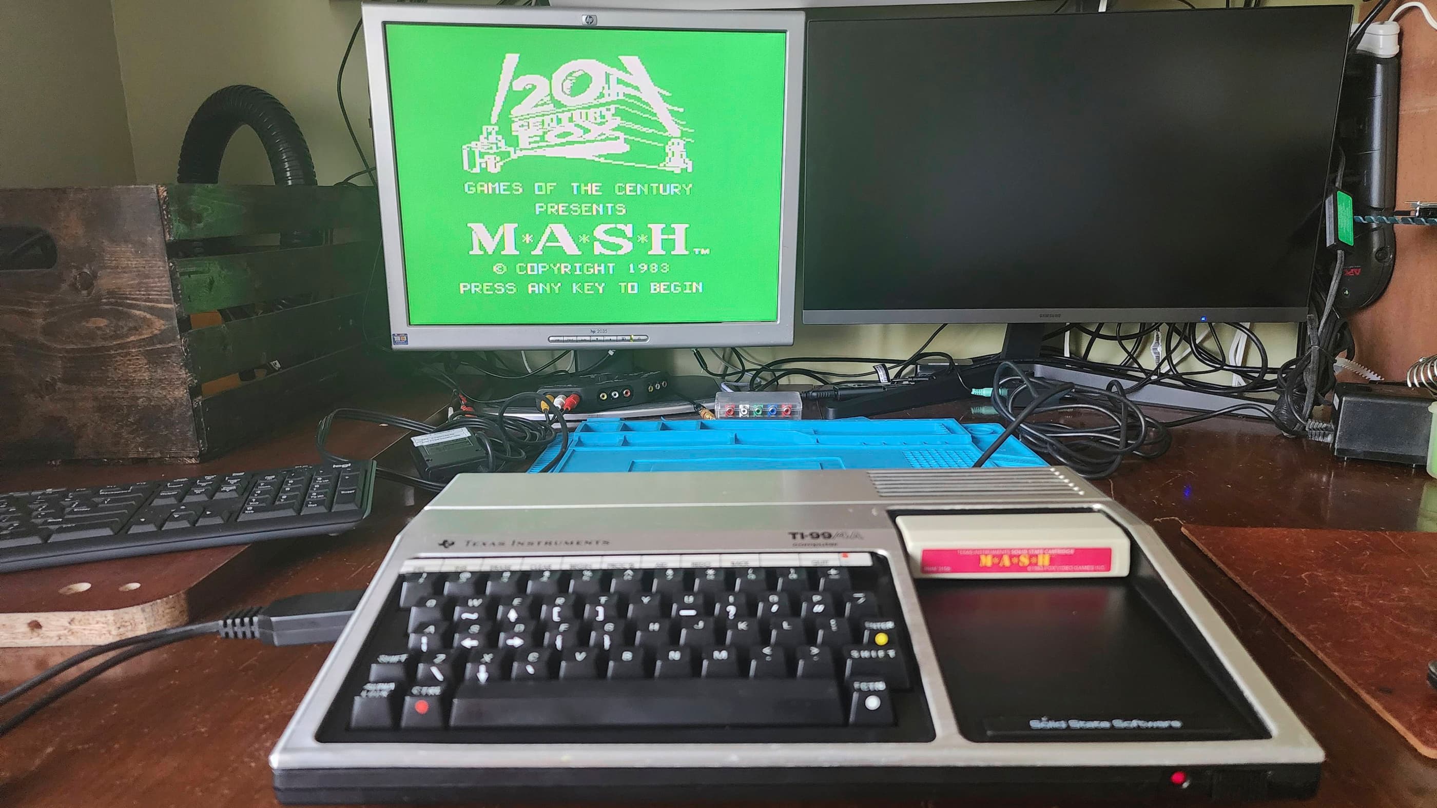
Interesting Fact: Despite being an upgrade on the original TI99/4, the TI99/4A was hampered soon after its release by Commodore’s aggressive marketing of the VIC-20 that forced Texas Instruments (TI) into slashing its price from $1150 USD to just $49 USD. (source) This meant that TI lost money on every machine that it made; though it did boost sales significantly. (source) The upgraded TMS9918A Video Display Processor (VDP) included a bit-mapped graphics mode and the 4-voice SN74489 sound generator was incredibly capable for its time. (source)
Condition When Acquired: Non-Functional
Current Condition: Fully Functional


Project Details: I acquired this machine and a second TI99/4A at almost the same time, so it was helpful to work on both concurrently. In the case of this computer, it came to me as untested, so I had no idea what to expect.
After unpacking it (it also came in its original box), my first step was to check the voltages coming from the external PSU. Once I confirmed that they were in spec, I hooked it up to a known, working video cable and powered up the machine. Unlike my other TI99/4A, this unit gave no signs of life outside of the illuminated power LED.
With different symptoms than my other machine, my first step was to disassemble the unit and then begin voltage testing. I first tested the internal power board followed by elsewhere on the main board, including the chips. The voltages were all normal – at least for the first 5 minutes, but more on that in a minute.
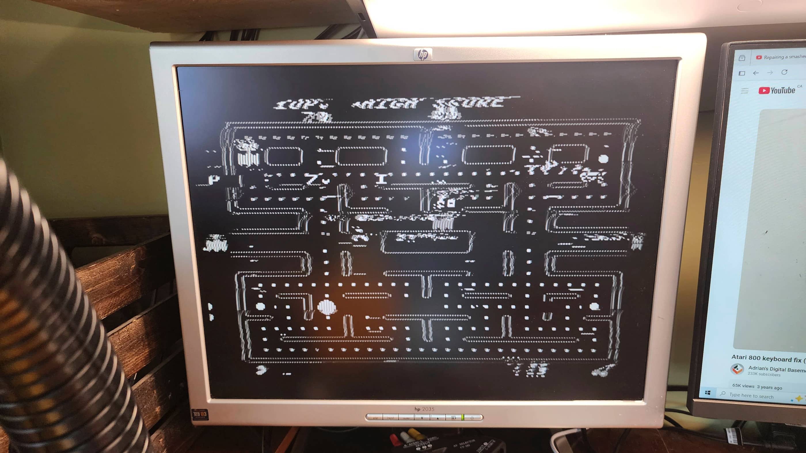
As I was concurrently working on my other TI99/4A, I swapped out the VDP (U100) and powered on the computer. Success! The system started successfully and I was able to perform several tests to verify it functionality. 🙂
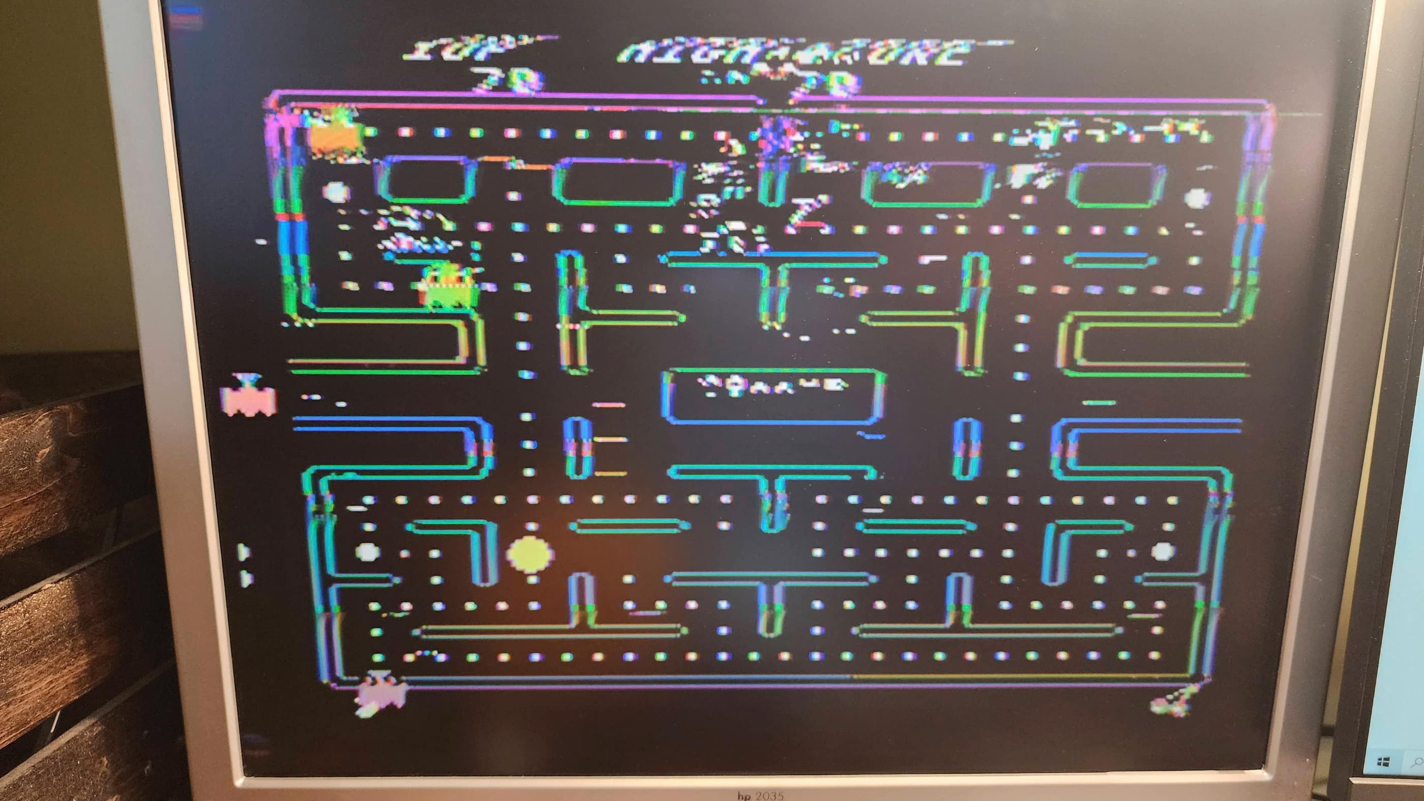
However, after 5 minutes or so of operation, the video output began to degrade into garbled graphics. 🤔 I first suspected that it might have been from the VDP not having a heatsink on it, but it continued to do so even after adding a heatsink. To confirm it wasn’t the VDP, I ordered in a new chip that I replaced it with. However, the same symptoms continued. Once the machine had warmed up, the graphics went from perfect to progressively garbled.
I then suspected that the DRAM might be at fault and on inspection, noted a cracked ceramic cap (C120). I replaced this but the symptoms continued. Voltage testing the DRAM also displayed nothing irregular even after the graphics began to deteriorate. I then made the decision to swap out the 4116 DRAM and replace it with modified and socketed 4264 DRAM to make the system run cooler by using less voltage. The SN74LS156N (U302) multiplexer was also removed and replaced with a brand-new, socketed replacement.
Unfortunately, after performing this DRAM mod on my other machine first, the only remaining 4264 DRAM I had was MT branded, which may come back to bite me later as it is known to be somewhat failure prone. Nonetheless, I powered up the computer but the symptom of degrading video graphics continued.
It was then that I found a forum on Atari Age where someone had a machine with the same symptom as this one. From this forum, I zeroed in on the video crystal, but it tested bang on for specs. What was weird however, was the fluctuation in voltage to the VDP began after it had been in operation for several minutes. This corresponded to the degradation of the video output. The voltage input on the VDP tested normal for several minutes after the computer was powered on, but once the voltages began to fluctuate, the graphics also began to deteriorate. That this didn’t occur until after the machine had been running for several minutes is why I was fooled when I first tested the voltages on the VDP shortly after power up.
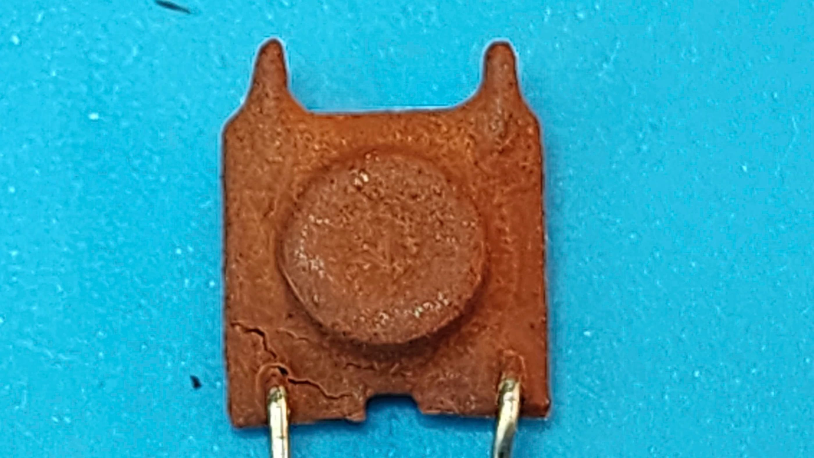
The Atari Age forum included a link to an old newsletter (page 6) that mentioned that the ceramic choke (L107 /L207 depending on your schematic) next to the crystal could go bad and that replacing it, had resolved similar video degradation issues. To test this, I swapped the choke from my other TI99/4A and powered the computer on. Bingo! With the swapped choke, the computer could stay on with any issues whatsoever. I’d solved the problem, now I just had to find a new replacement.
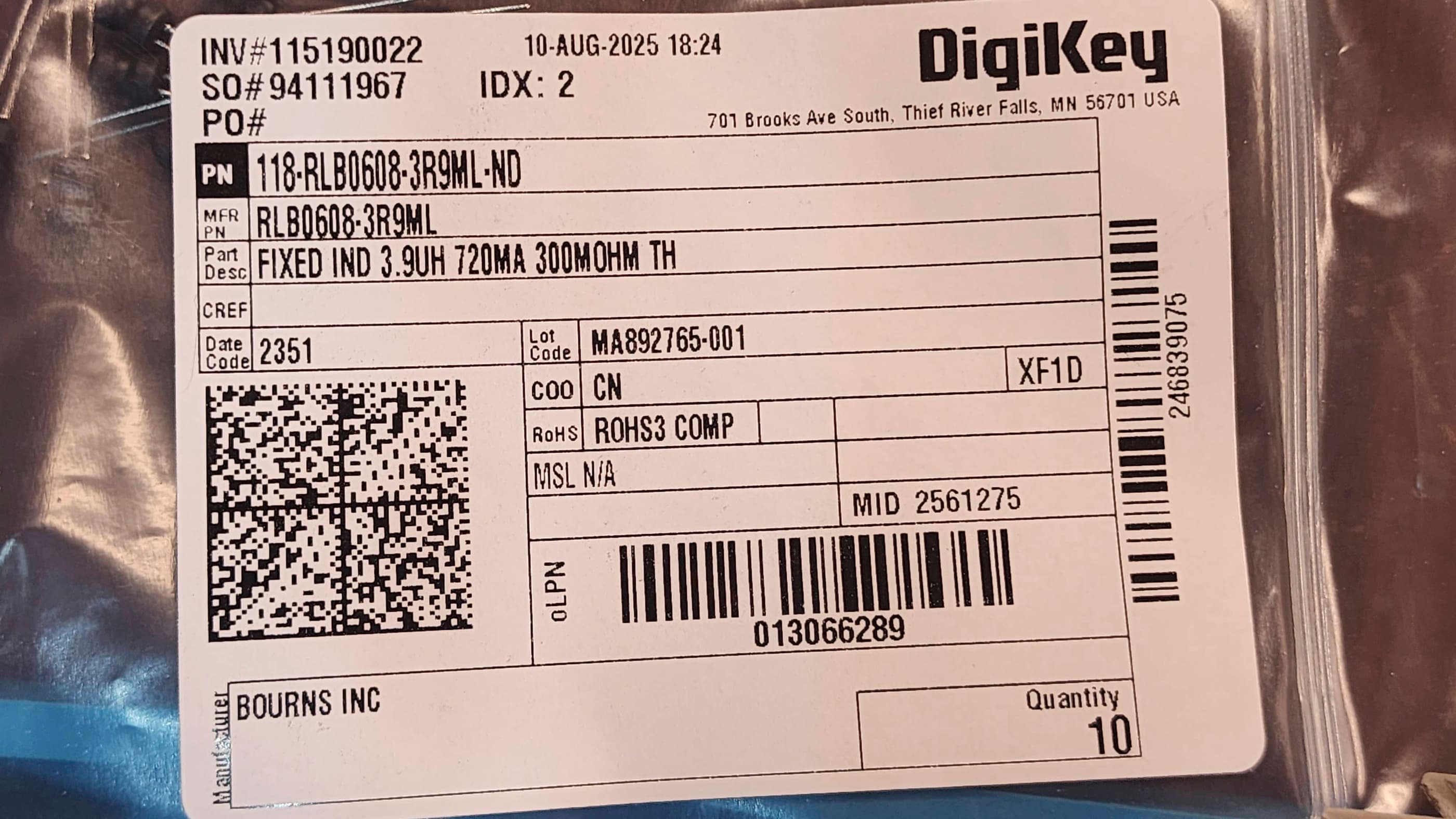
Thanks to the forum I knew that the choke would be 3.9 μH as the original schematics and parts lists, did not provide this information. However, it also seemed that a replacement could have a higher range of tolerance for μH as the writer of the newsletter article noted that he’d experienced no issues between 4 and 120μH. Given, the specific calculations in the Atari Age forum, I decided to first try a 3.9μH choke.
So, I ordered in a new choke from Digikey and replaced the original. On closer inspection, I could see that the original ceramic choke was cracked which aligned with what the writer of the newsletter had observed, that “the choke has the ability to soak up as much moisture as possible. I have dissected a number of these chokes to find that the interleaved windings have all manner of green stuff growing in and around them.”
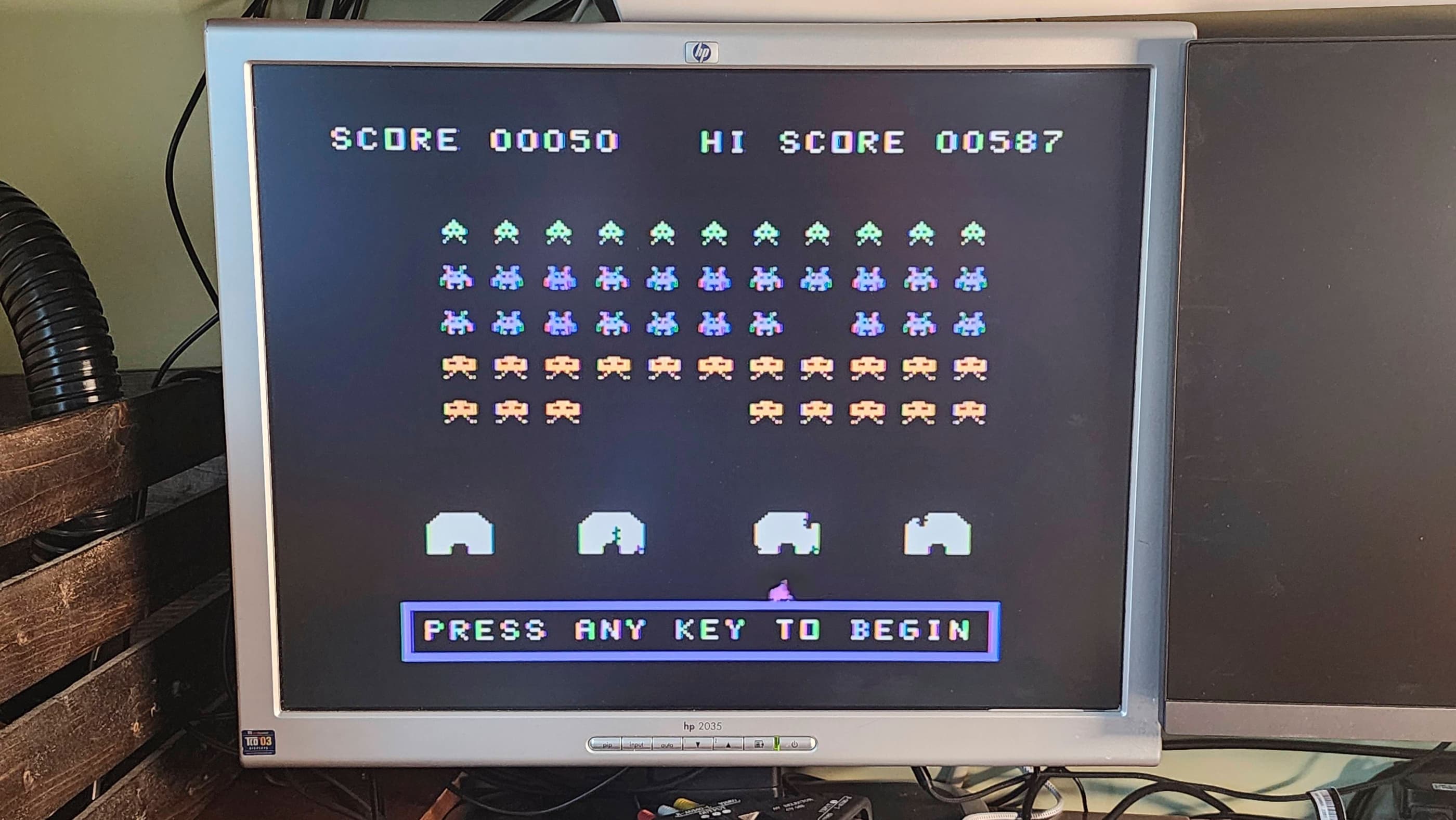
After installing the new choke, I powered the machine on and then began testing. I let the machine run for 30 minutes or more multiple times, and not once did the video degrade. It remained stable and operational. Success!! 😀
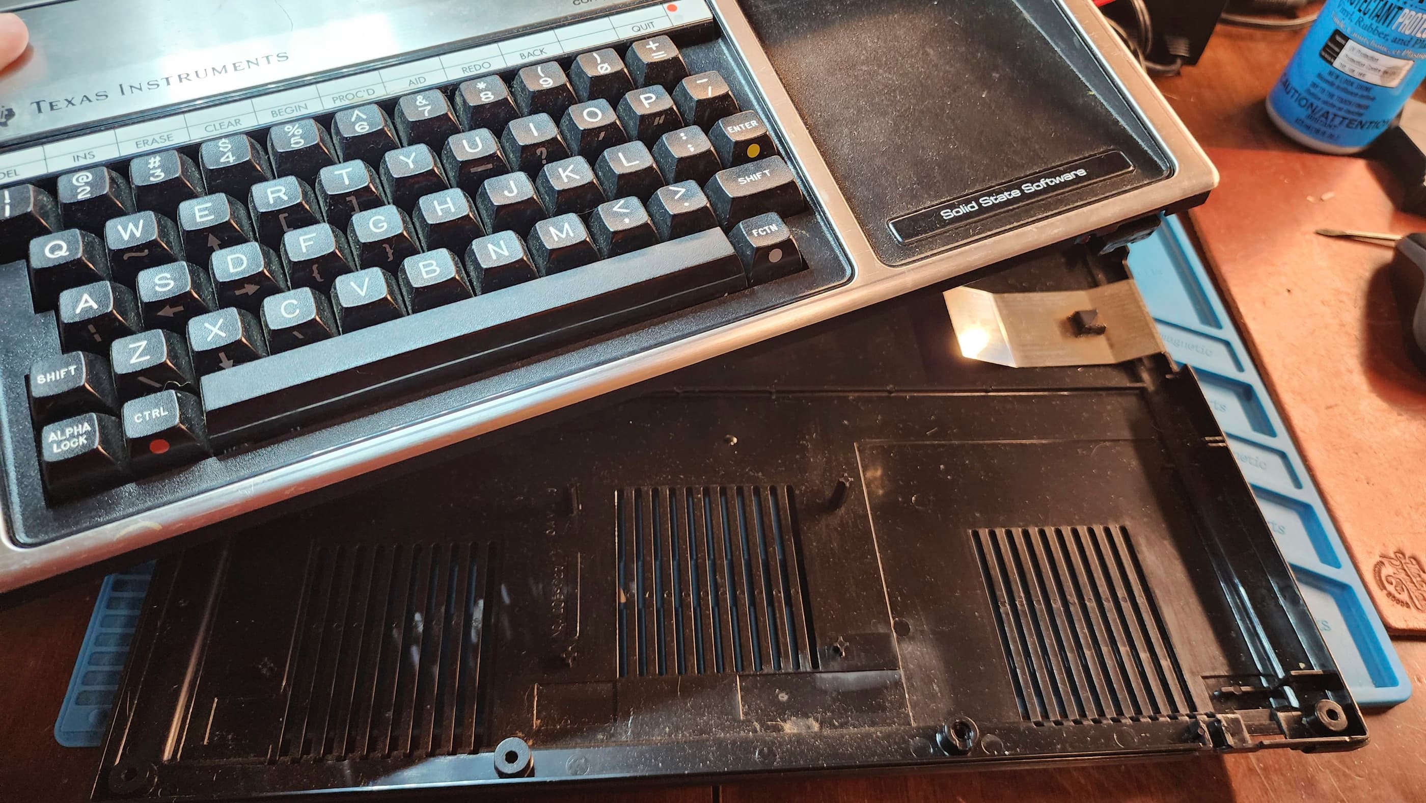
As I had with my other TI99/4A, I re-capped the power board and the main board. On testing, I noted that a couple keys on the keyboard weren’t working entirely at 100%, so I disassembled the keyboard and used a heat gun to peel back, clean, and reseat the mylar membrane. This resolved the issue.
I then cleaned the unit thoroughly and ran it through more testing. Everything worked perfectly. I now have two fully working TI99/4As in my collection. 🙂
Parts and Products Used: 99% isopropyl alcohol; Chemical Guys Natural Shine; Deoxit D5; internal power board electrolytic capacitors (radial): 35v 4.7μF (1); internal power board electrolytic capacitors (axial): 12v 470 μF (1); 16v 47μF (2); 25v 1000μF (1); 35v 3300 μF (1); Main Board electrolytic capacitors (axial): 25v 10μF (1); 25v 22μF (5); 25v 100μF (3); L107/L207 choke replacement: 3.9μH 720MA (1); Video Display Processor (VDP): TMS9918A; DRAM: 4264-15 (8) – modified by removing PIN 1 and then bending and extending PIN 8 to join PIN 9; Multiplexer chip: SN74LS156N (1); IC Sockets: 14 PIN DIP machine pin (9); Aluminum heatsinks; double-sided thermal IC tape
32-Bit

Commodore Amiga 1200
Years (1992-1996)
Interesting Fact: The A1200 represents the third generation of Amiga computers, and like the A500, was targeted specifically at the home market. (source) Unfortunately, by the time of the A1200s release in October, 1992, Commodore was already bleeding money and would declare itself insolvent in April,1994. (source) For an excellent history of Commodore and the Amiga, I would recommend reading: “A History of the Amiga” by Jeremy Reimer and watching “Amiga Story” by Nostagia Nerd. Both of these multi-part sources are fantastic.
Condition When Acquired: Non-Functional / Unknown
Current Condition: Fully Functional


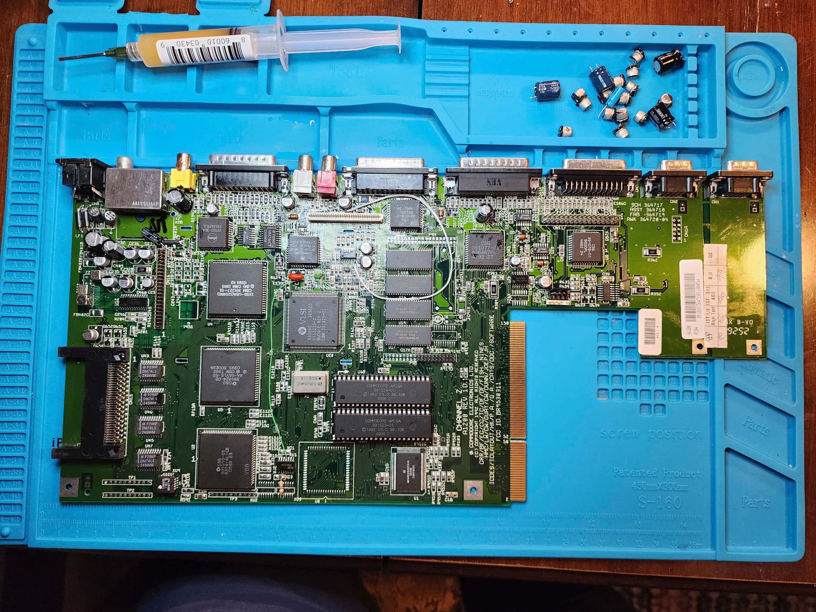


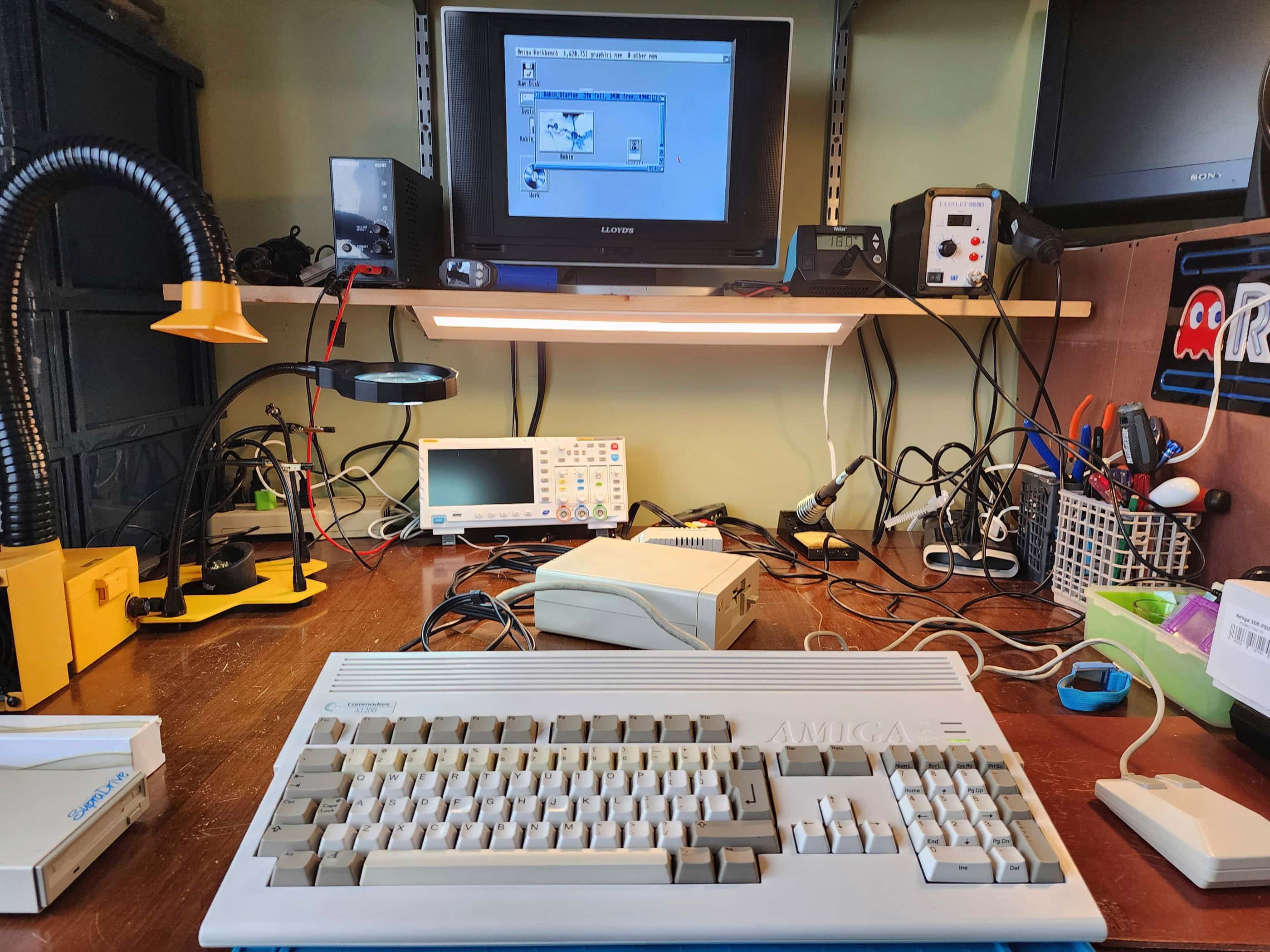


Project Details: This is not my computer; it’s my brother-in-law’s (BIL). Yet, since it’s in the family, I’m counting it as part of my collection. 😁
A life-long Amiga aficionado, my BIL bought this system new when he graduated high school in 1993. After a few years of use, life happens and people move, change jobs, etc., and his beloved Amiga 1200 went into deep storage sometime in the late 90s, though he never stopped thinking about it.
After watching me hack out a side hobby of repairing old consoles, he asked if I’d take a look at the 1200 and see if I could re-cap it for him. To be honest, it’s one thing when you’re risking your own consoles to the dangers of meddling, but it’s another when you’re doing it for someone else, let alone close family. Couple that with the rarity of the system, and I was a bit nervous to say the least. 😯
Nevertheless, I accepted the challenge because as I’ve mentioned before, I consider Amigas to be the best gaming machines of their era. I had an A500 (as did my wife and BIL), but the A1200 was the next level successor in terms of speed and processing power. Unfortunately, it arrived on the scene when Commodore was going down the tubes and cutting costs – something that I could plainly see while working on this project.
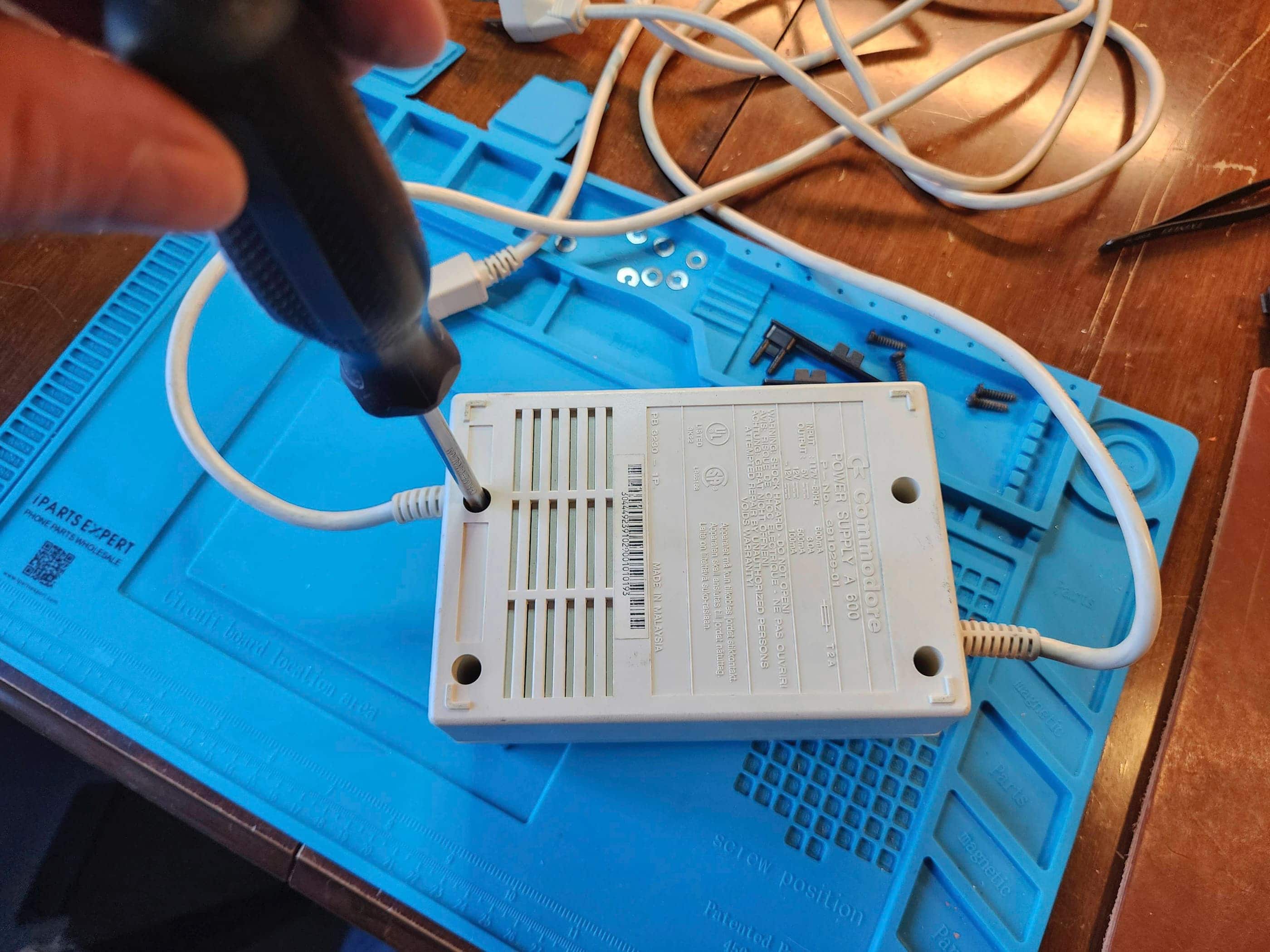
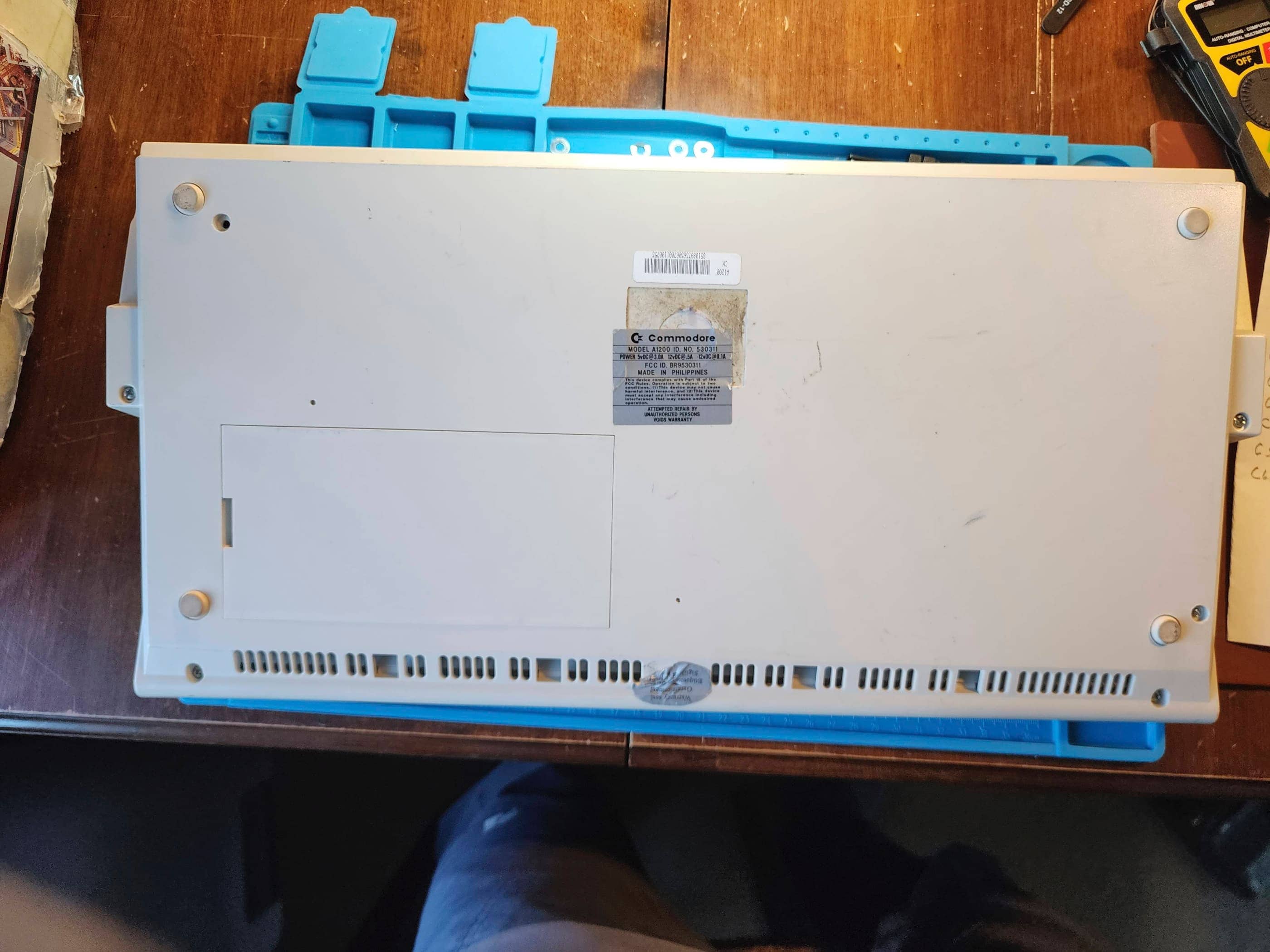
After bringing the A1200 home, the first thing I did – even before unpacking the computer – was test the OEM A600 power supply. Noting that the voltages were badly out of spec, I put an order into Console5 for both a power supply re-cap kit and an A1200 re-cap kit. While I waited for everything to arrive, I set about cleaning the unit.
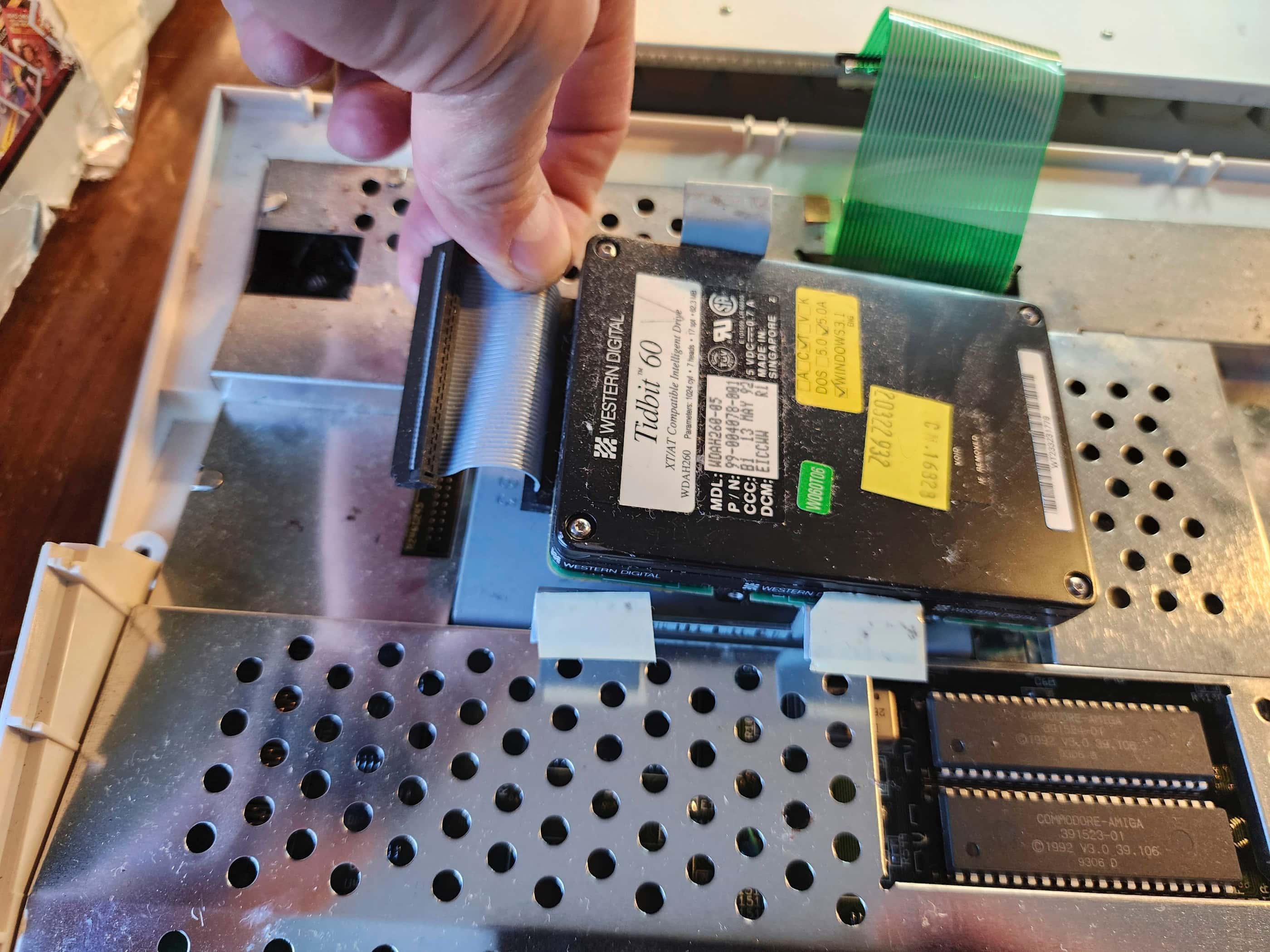
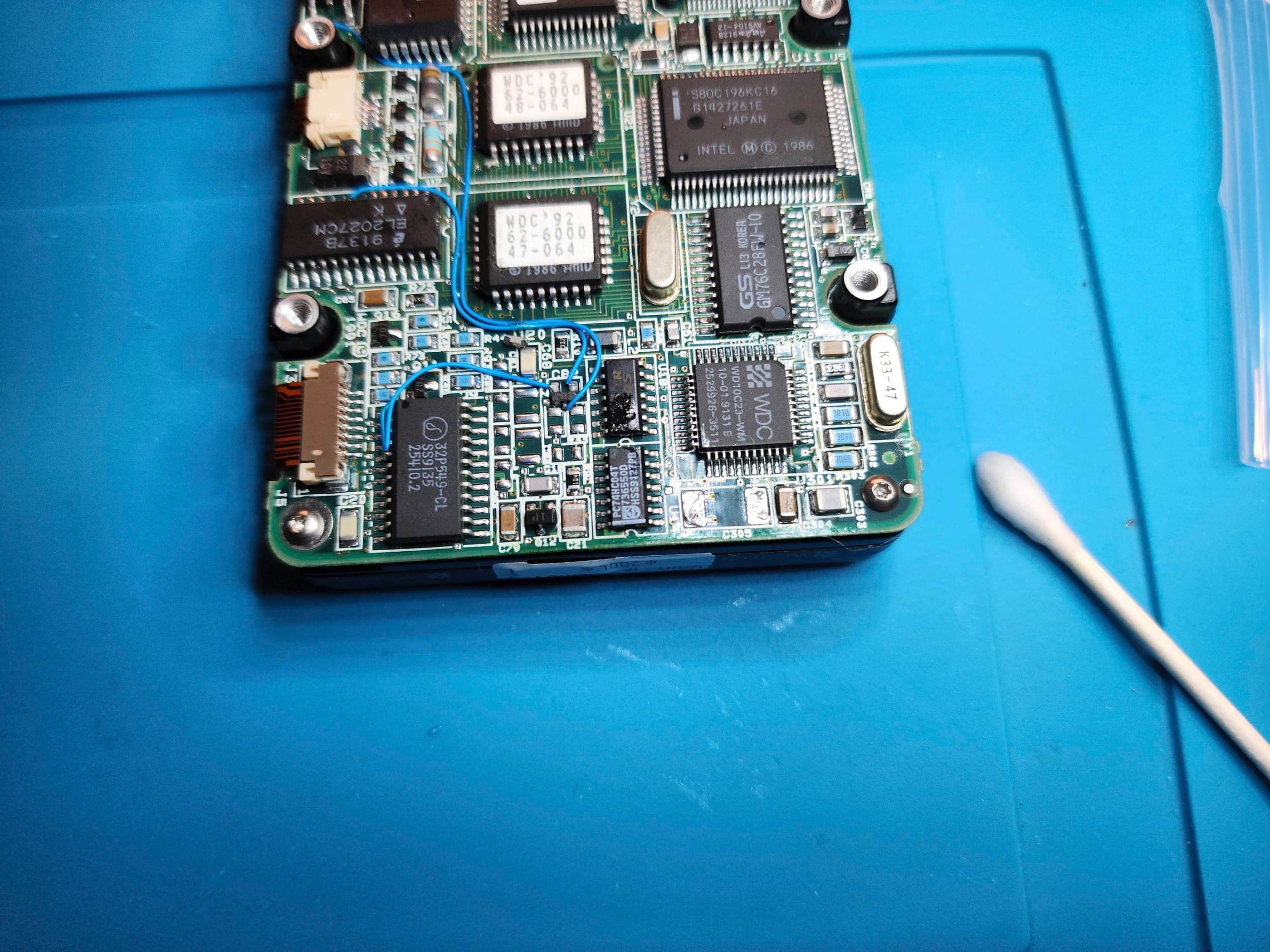
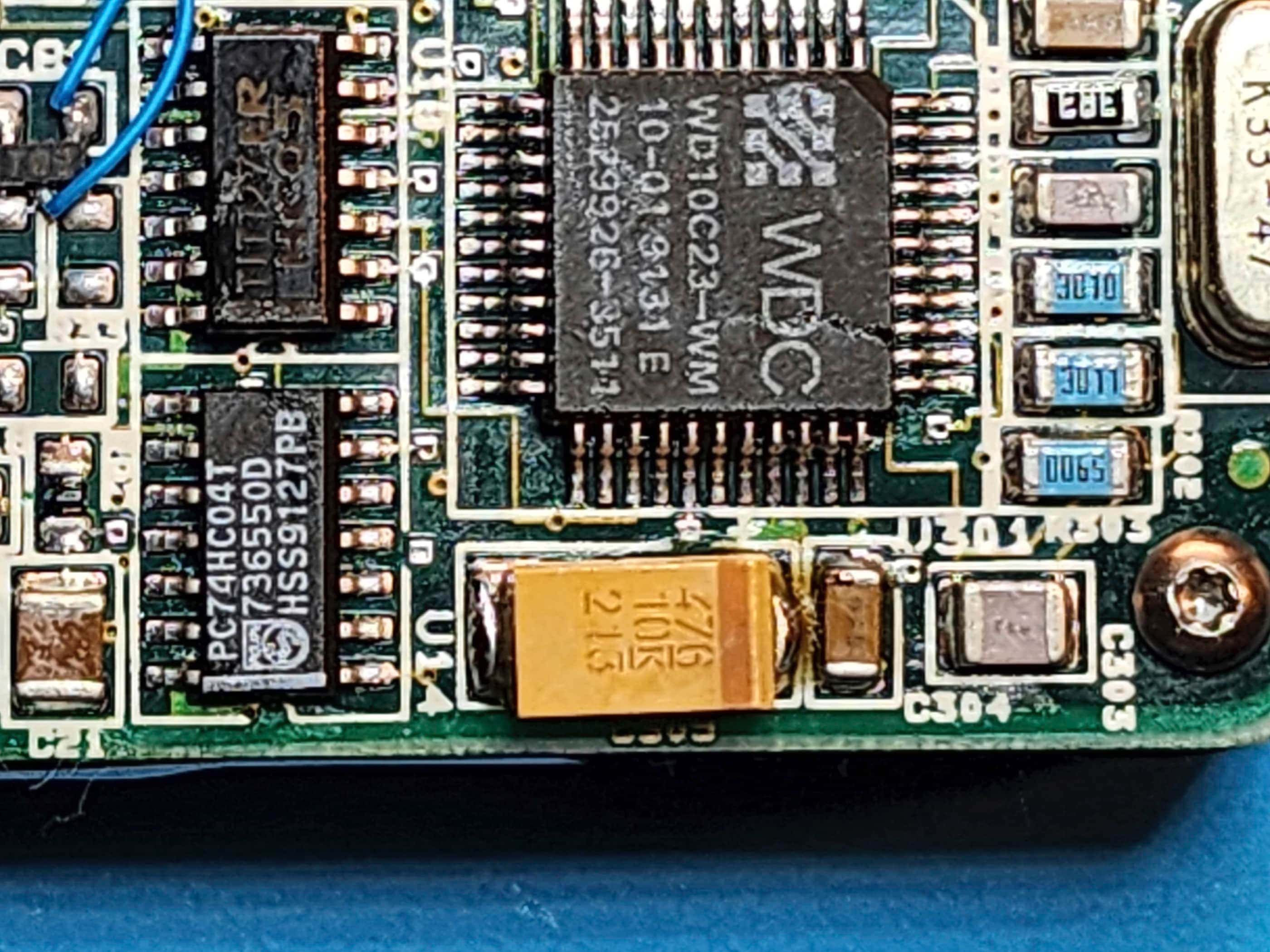
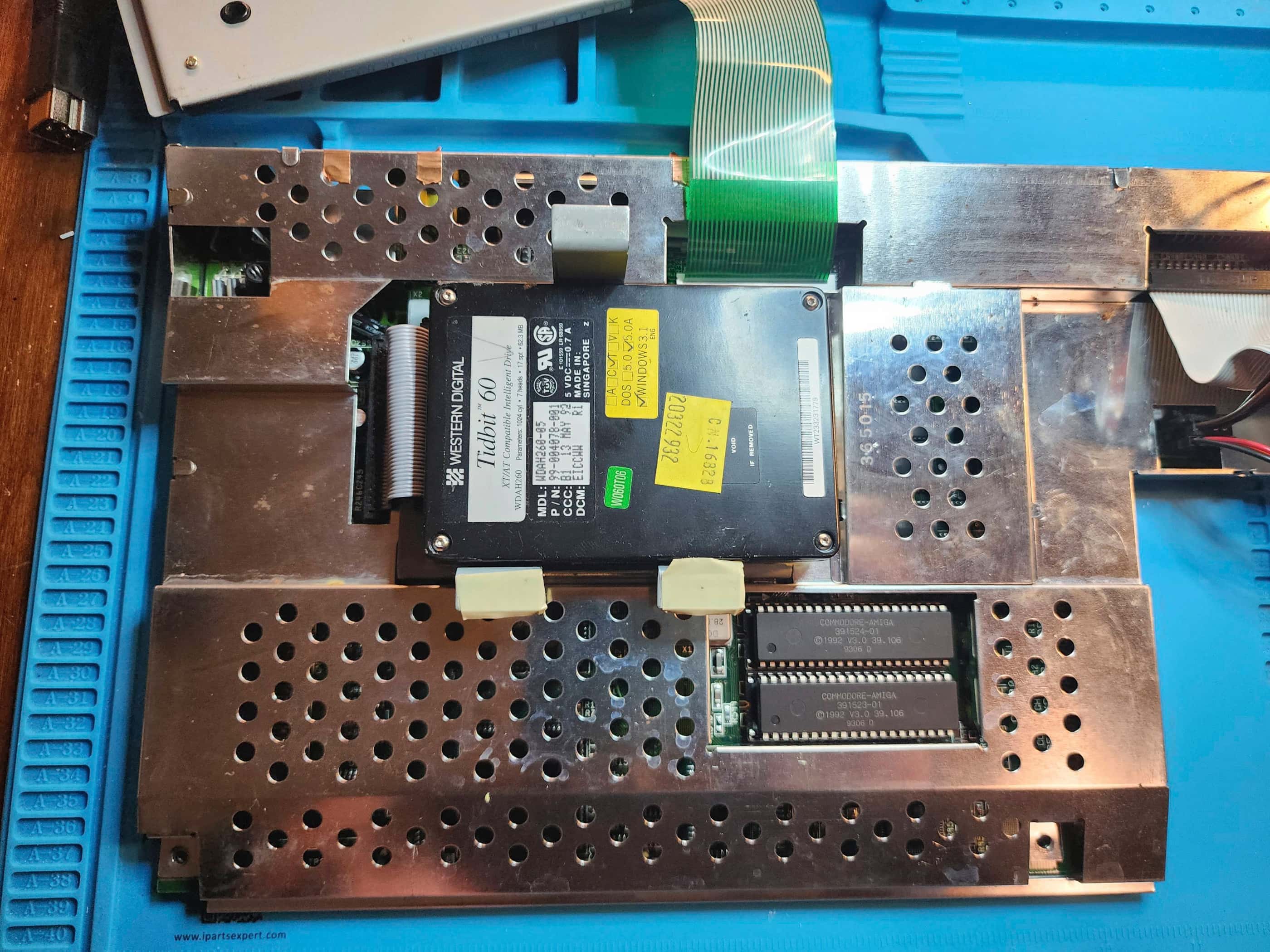
As soon as I removed the A1200 from the box, I heard something rattling under the hood. Once I had it open, I noted two obvious problems related to its years of storage: 1) a tantalum capacitor had fallen off the hard drive (the cause of the rattle); and 2) a poorly soldered, 50v 2.2μF smoothing / decoupling capacitor near the Video DAC had also come loose, and on further inspection, had lifted a pad and severed a trace in the process.
I also inspected the capacitors, particularly the SMDs, and while I didn’t see any obvious leakage, I knew from reading, that the ones used by Commodore at this time were about as reliable as the caps used by Sega for the Game Gear. Both of which had high failure rates due to using the cheapest parts available.
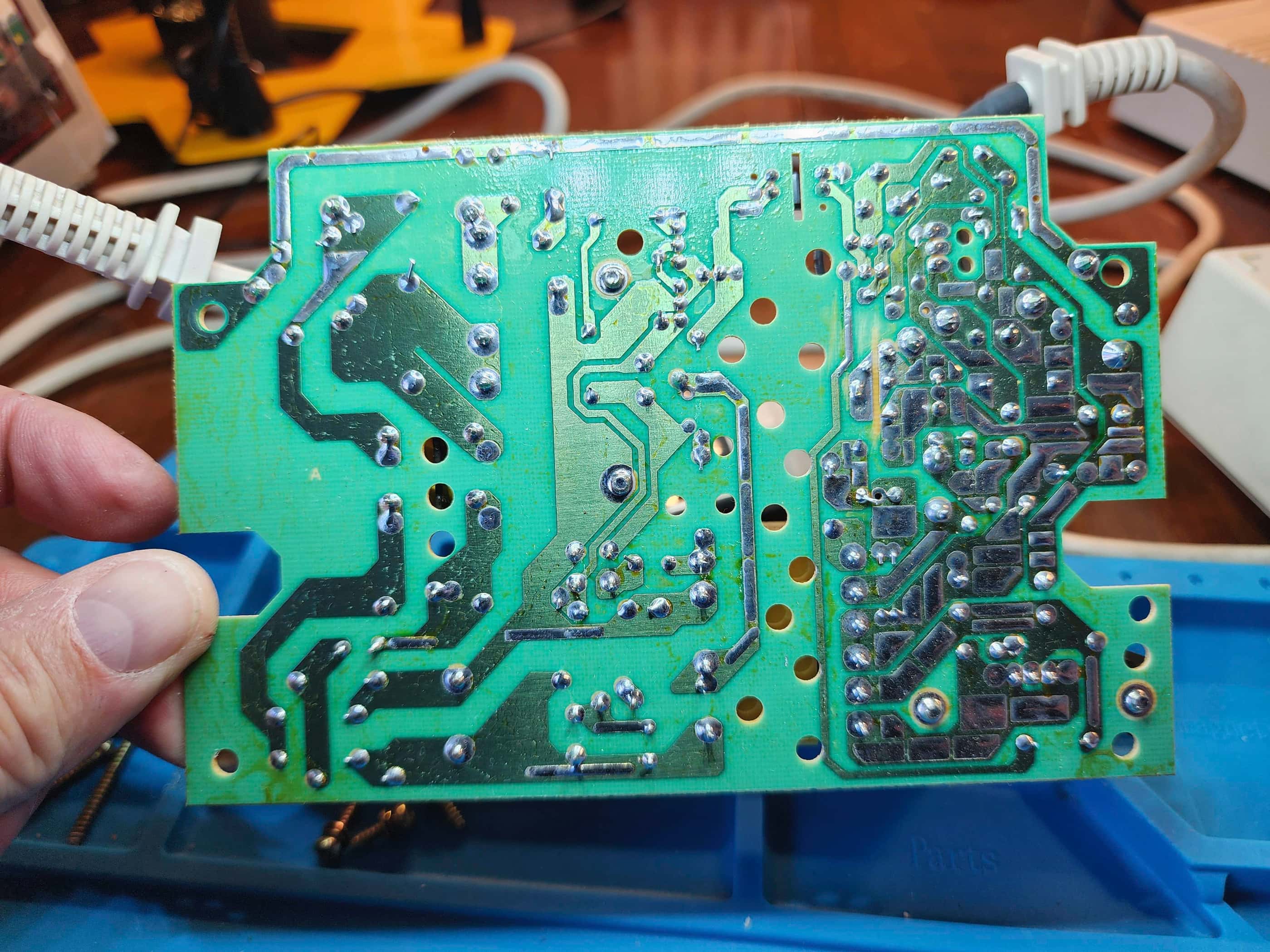
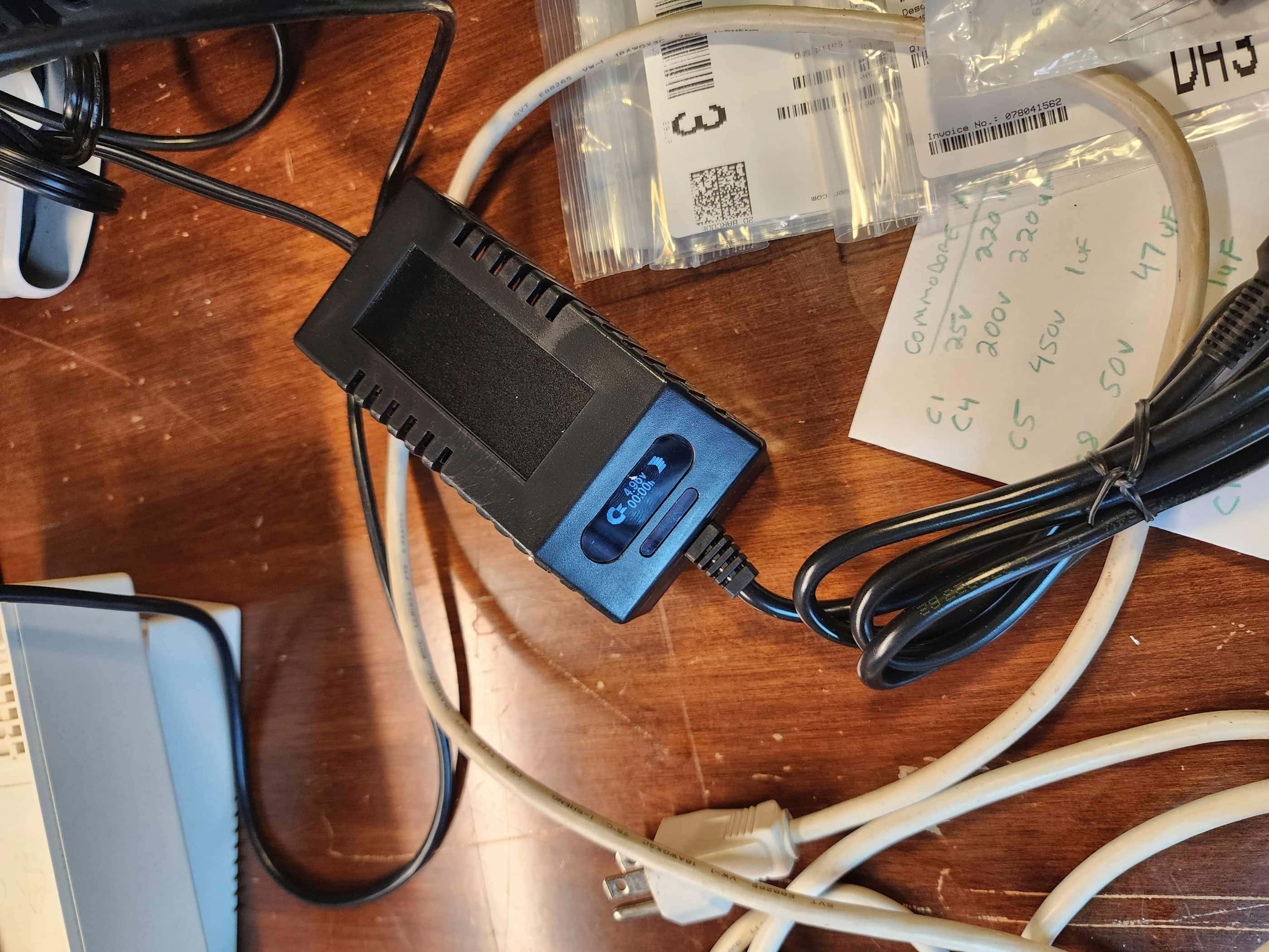
Once the re-cap kits arrived, I proceeded to re-cap the A600 power supply and test the voltages. Unfortunately, the re-cap didn’t fix anything and instead of wasting more time on repairing it, I ordered a new power supply from Keelog – a Polish company that has had great reviews for its retro power supplies. While I was at it, I also ordered a new power supplies for my VIC 20 and one for a ColecoVision.
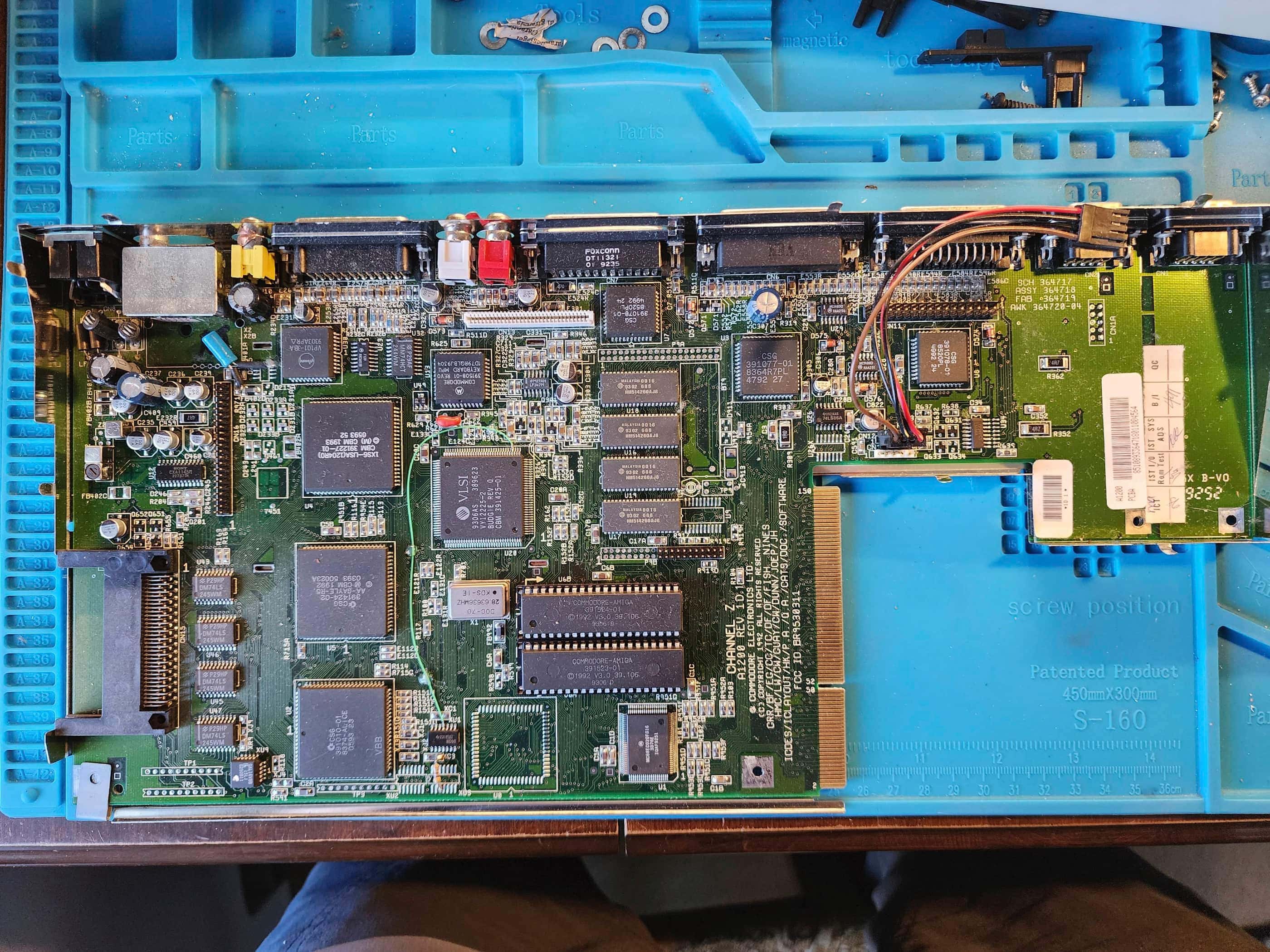
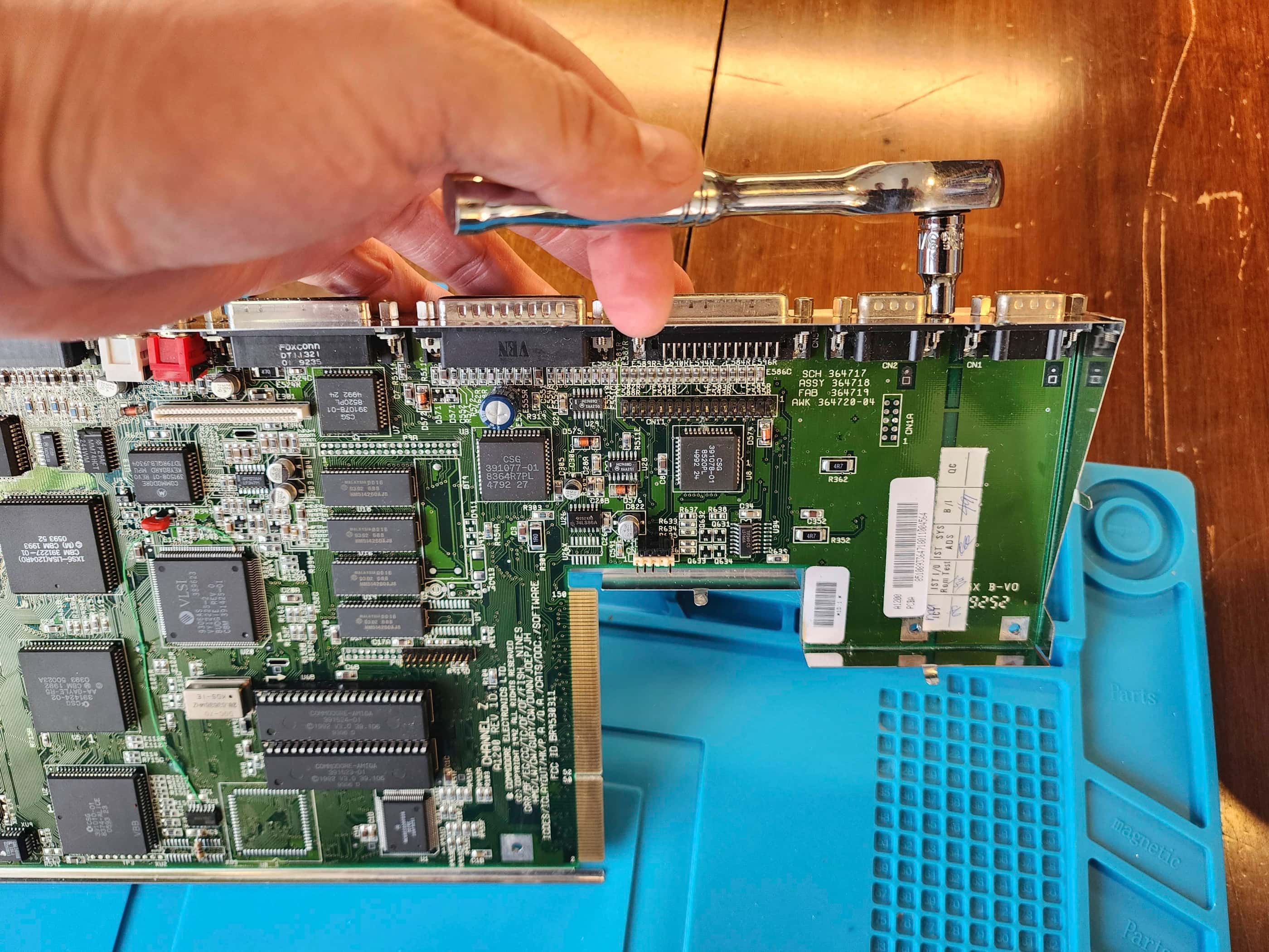
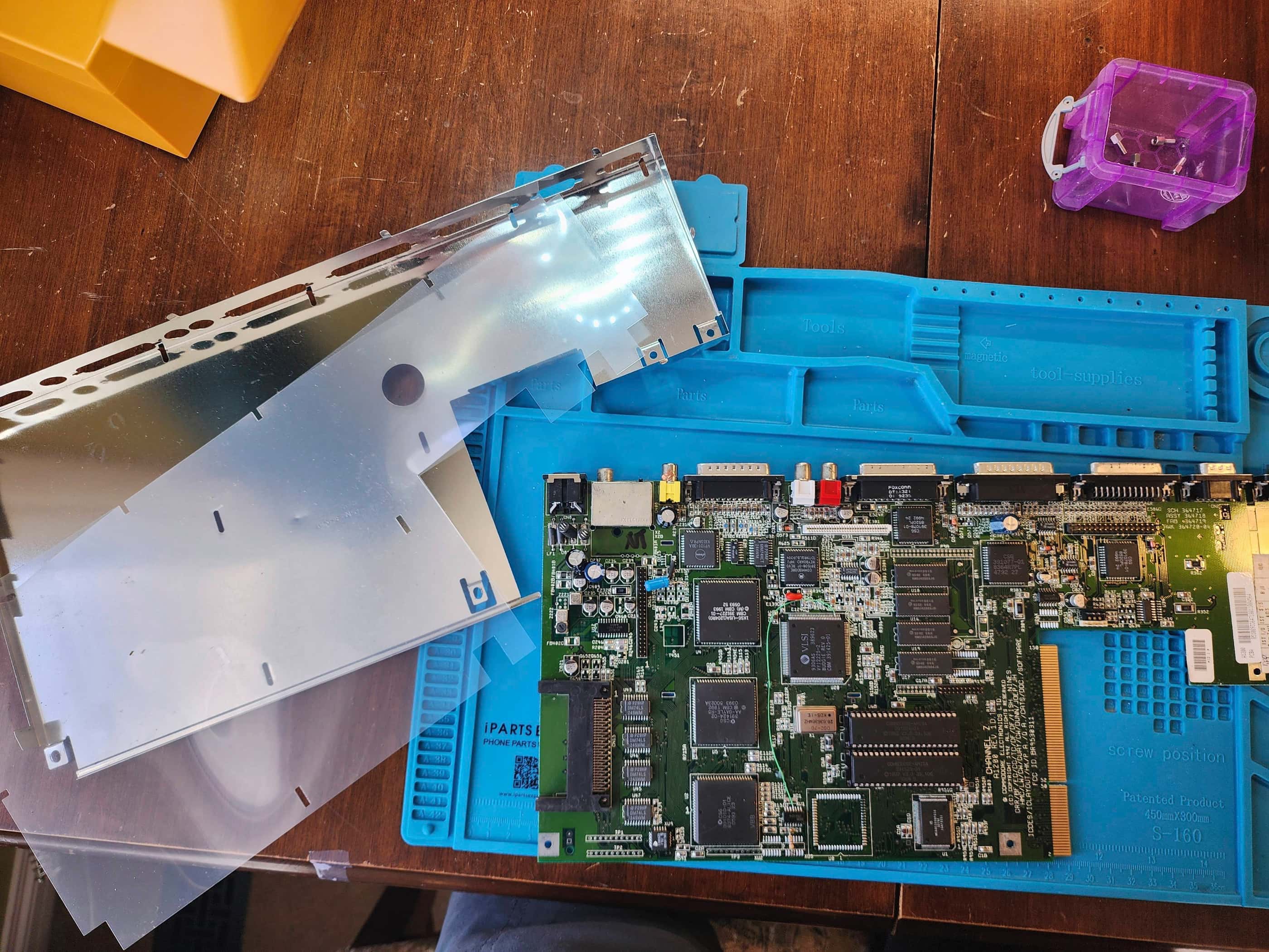
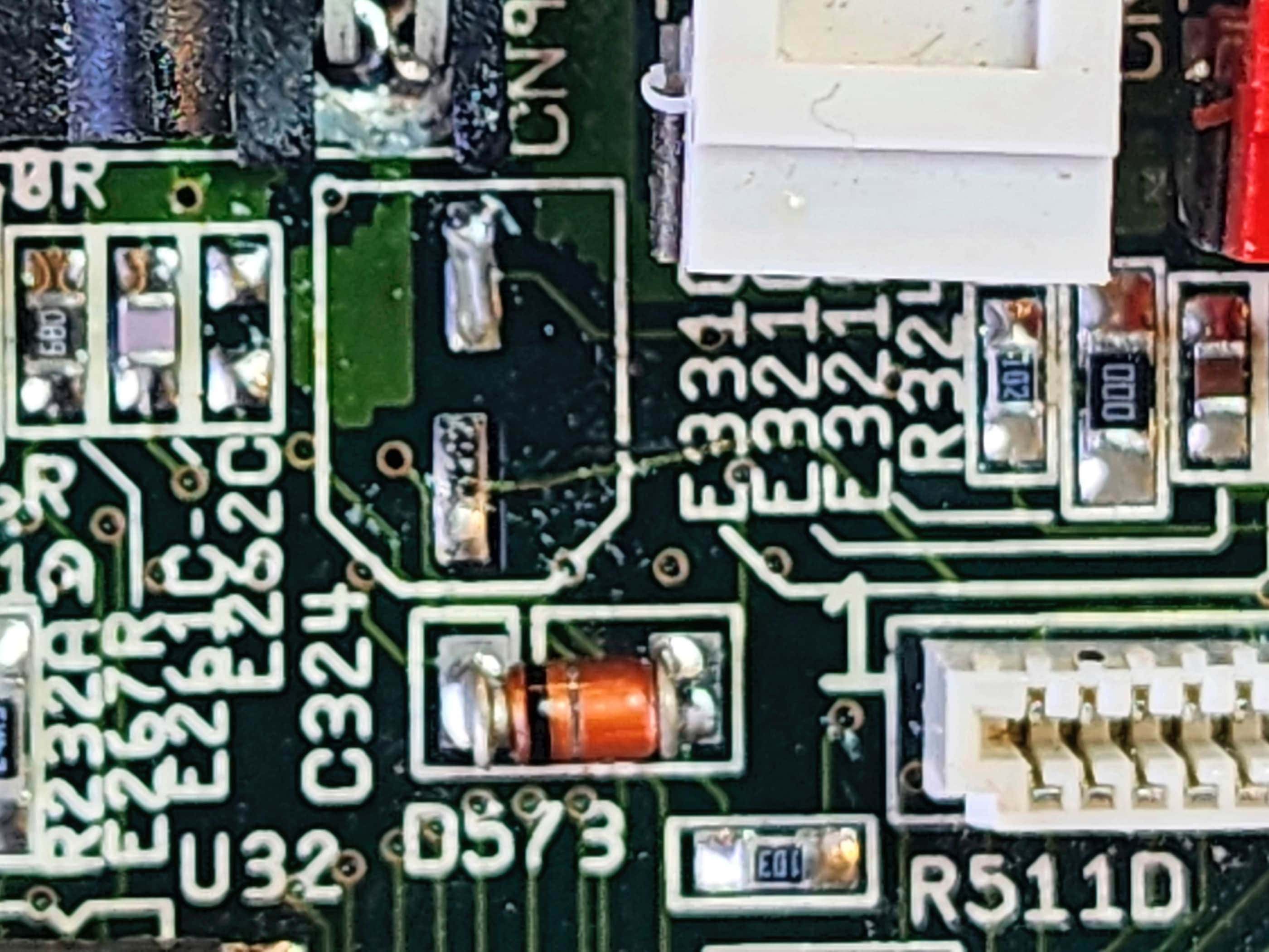
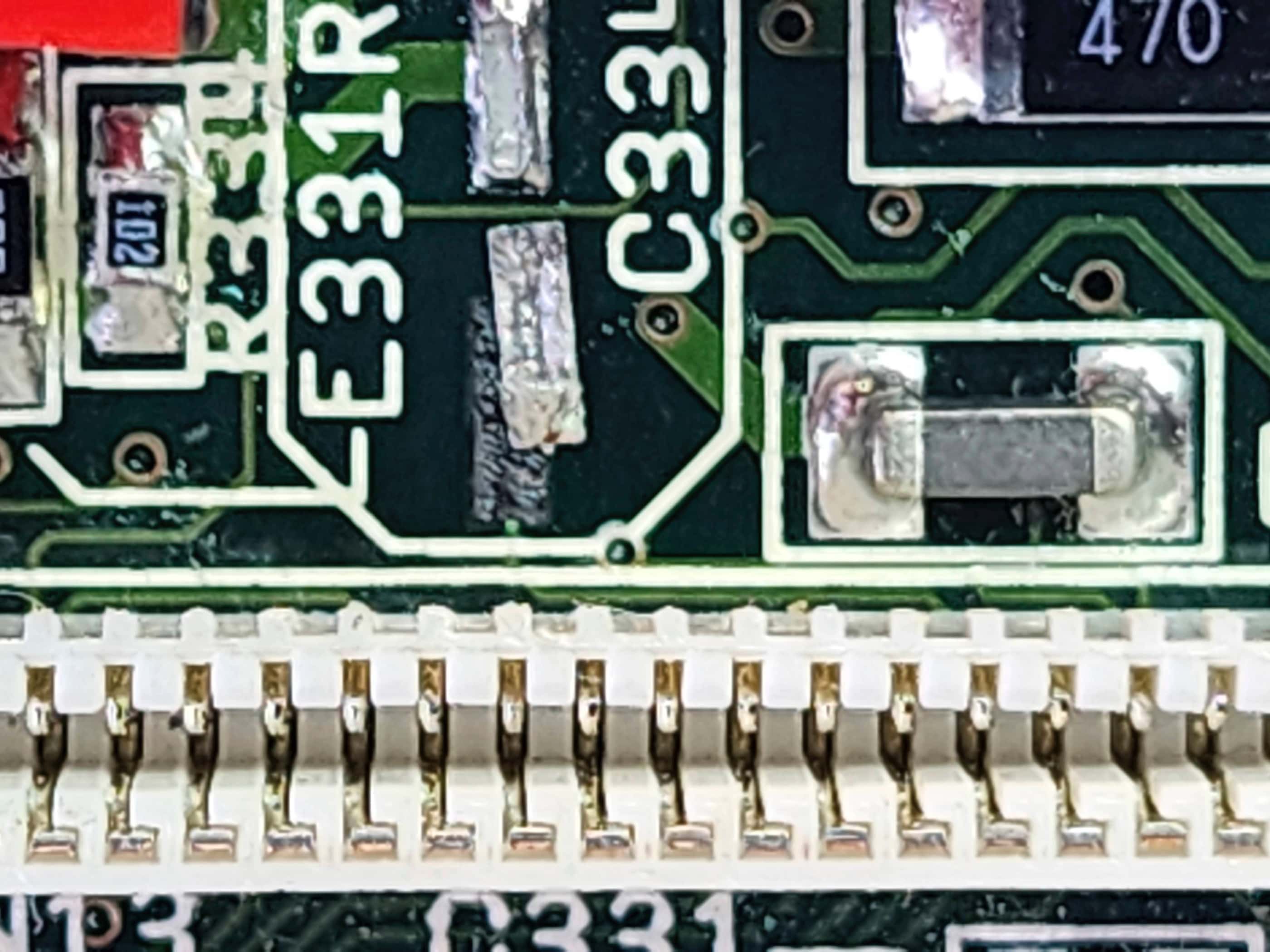
While waiting for the power supply (which only took 2 weeks to come), I set about working on the Amiga itself (FYI the board was REV 1D). Using my heat gun at the same settings that I’ve used for other boards, coupled with copious amounts of flux, I began to remove the SMD caps. The first few went as planned, but the left (C324) and right (C334) audio output caps proved stubborn and in the process the pads and traces lifted. Crap! 😯
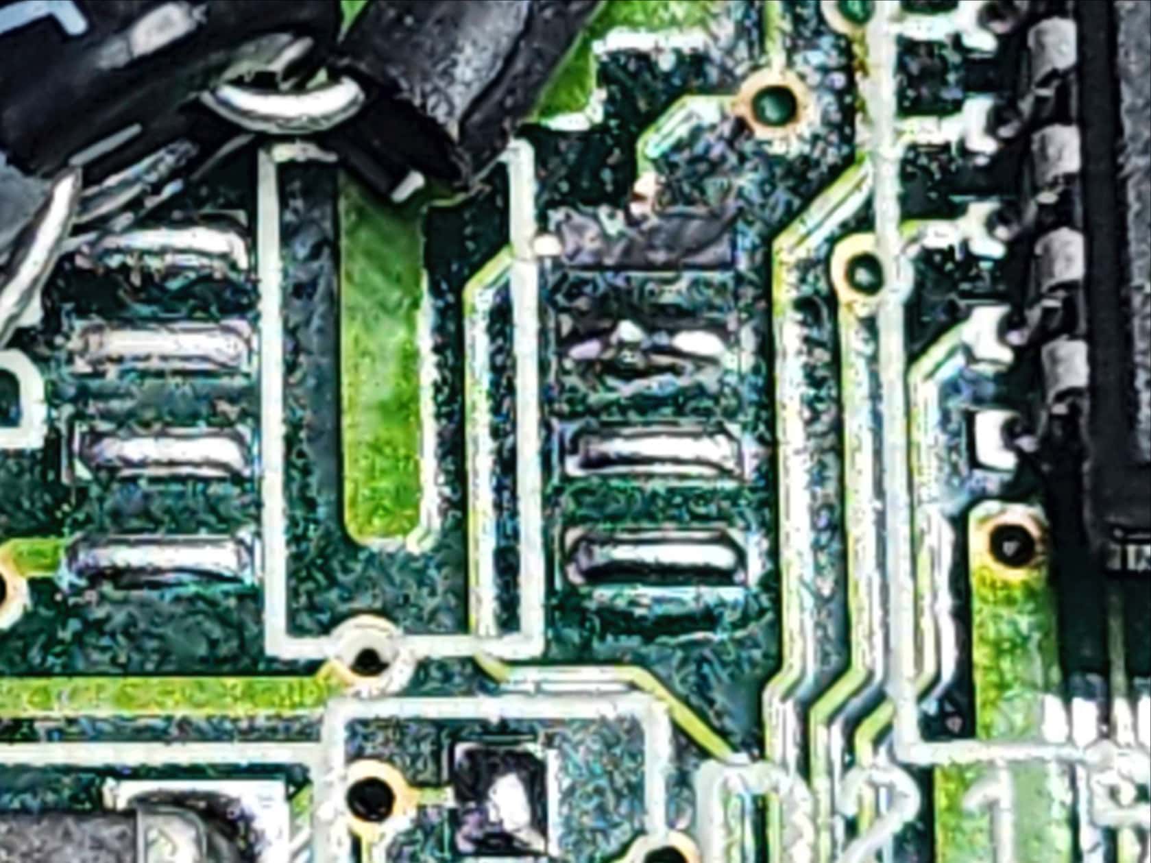
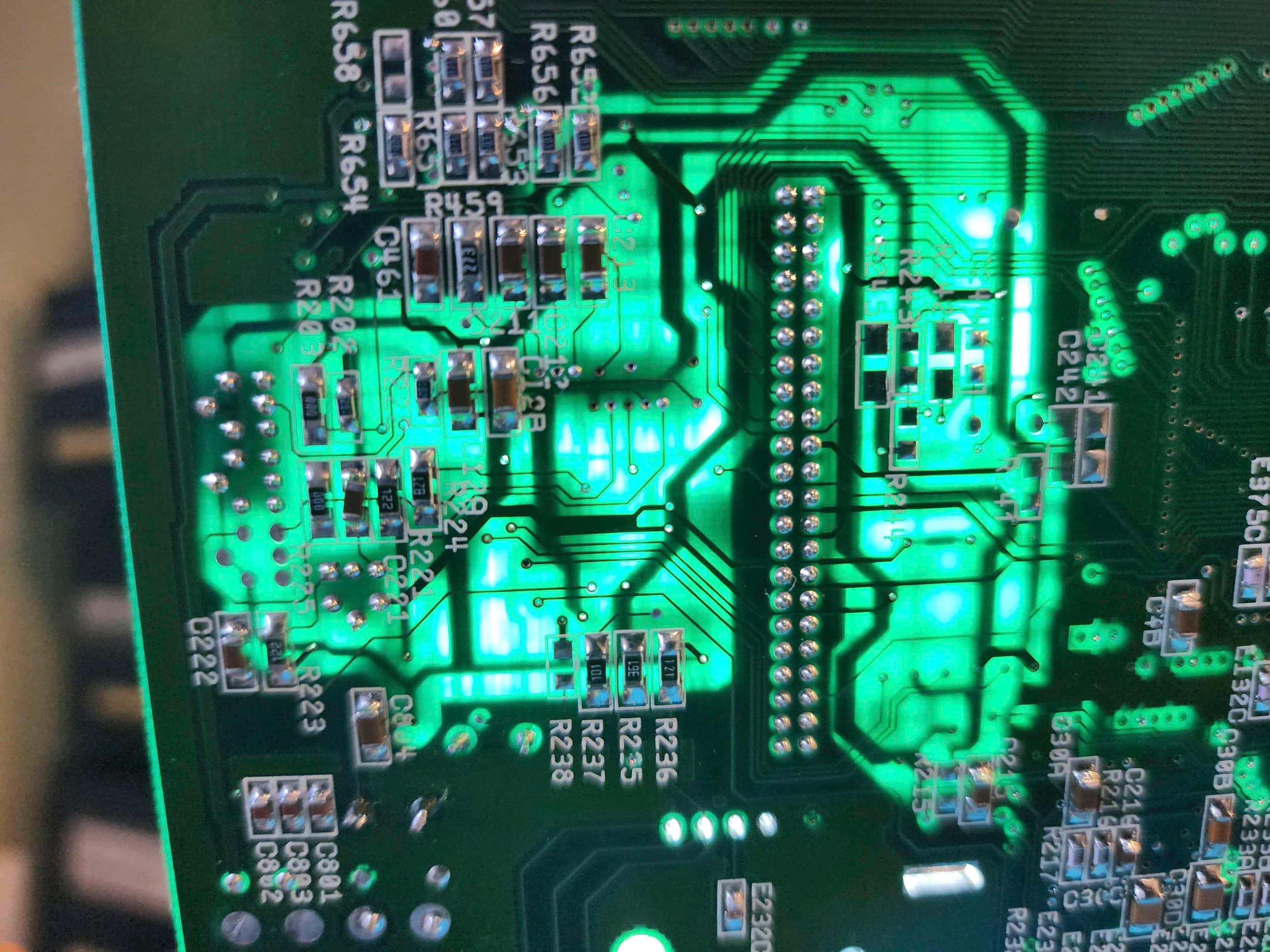
The same also happened for C409, C235, and C821. Fortunately, the traces were only severed for C334 and C409, and using high heat epoxy, I could reattach the pads and glue down the traces. For C334, the pad would not reattach to the trace, so I looked at the schematic and discovered that it was easily fixed by running a jumper from the anode end of the cap to pin 7 of the LF347M chip. For C409, the issue was extending the solder blob from the anode pad to the via that connected to the power circuitry sandwiched inside the board along with the backside of the board. This was important because the +5v of power that supplies the CXA1145M video encoder is supplied through here.
Having traces and pads lift like this was a fairly new experience for me and on a double-sided board with sections of sandwiched circuitry, it meant that I spent a lot of time reading the schematic to make sure I wasn’t overlooking something. That this happened at all made me question my abilities (and sanity), but there’s always a risk when you perform seemingly minor surgery. To be fair though, I do think that when compared to other boards I’ve worked on, the traces and pads were shallow and lightly affixed during the manufacturing process, making them more susceptible to lifting while heating.
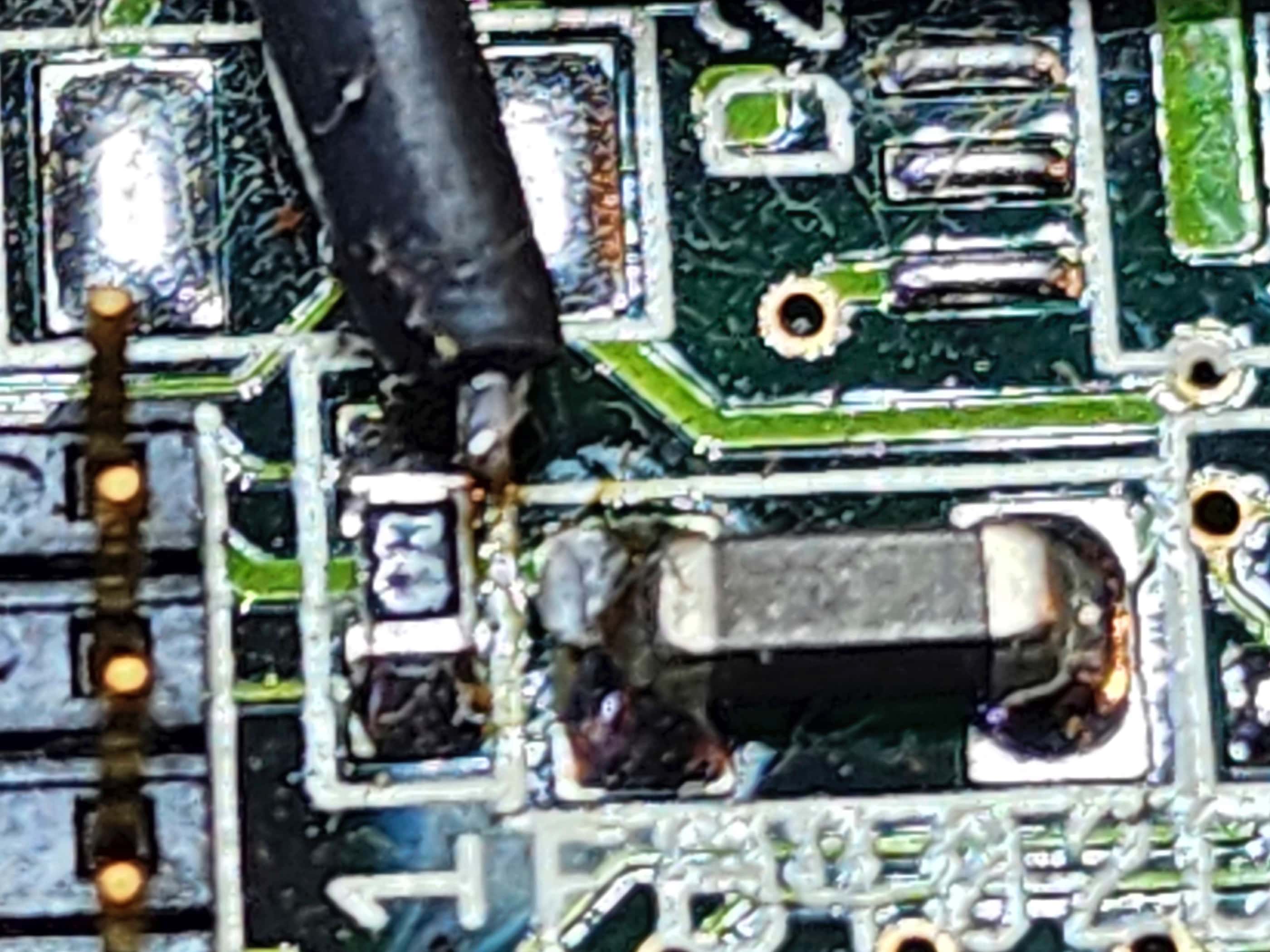
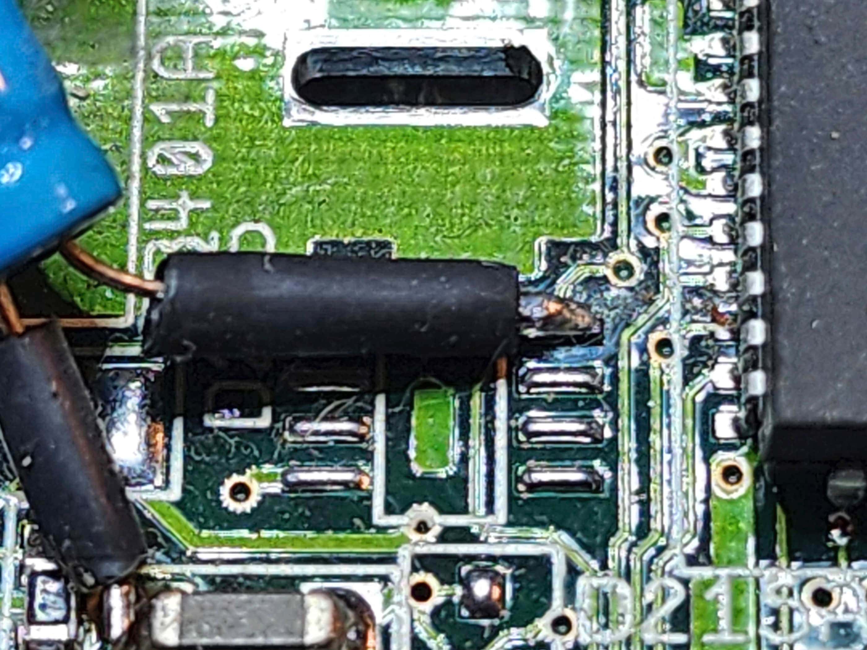
Now that my follies had been corrected, I set about fixing the manufacturer’s mistakes, one of which, proved to be the most difficult fix of the entire endeavour: the lifted pad and severed trace for the 50v 2.2μF ‘add on’ decoupling or smoothing capacitor. I say ‘add-on’ because it was obviously an afterthought at the factory and does not appear in the schematics. In fact, I searched for quite a while and saw lots of REV 1D boards online and no one had this capacitor added. As Console5 notes, “Commodore seemed to use whatever was available on the market that met minimum specs and fit.” This statement also fits with the overall board quality as well.
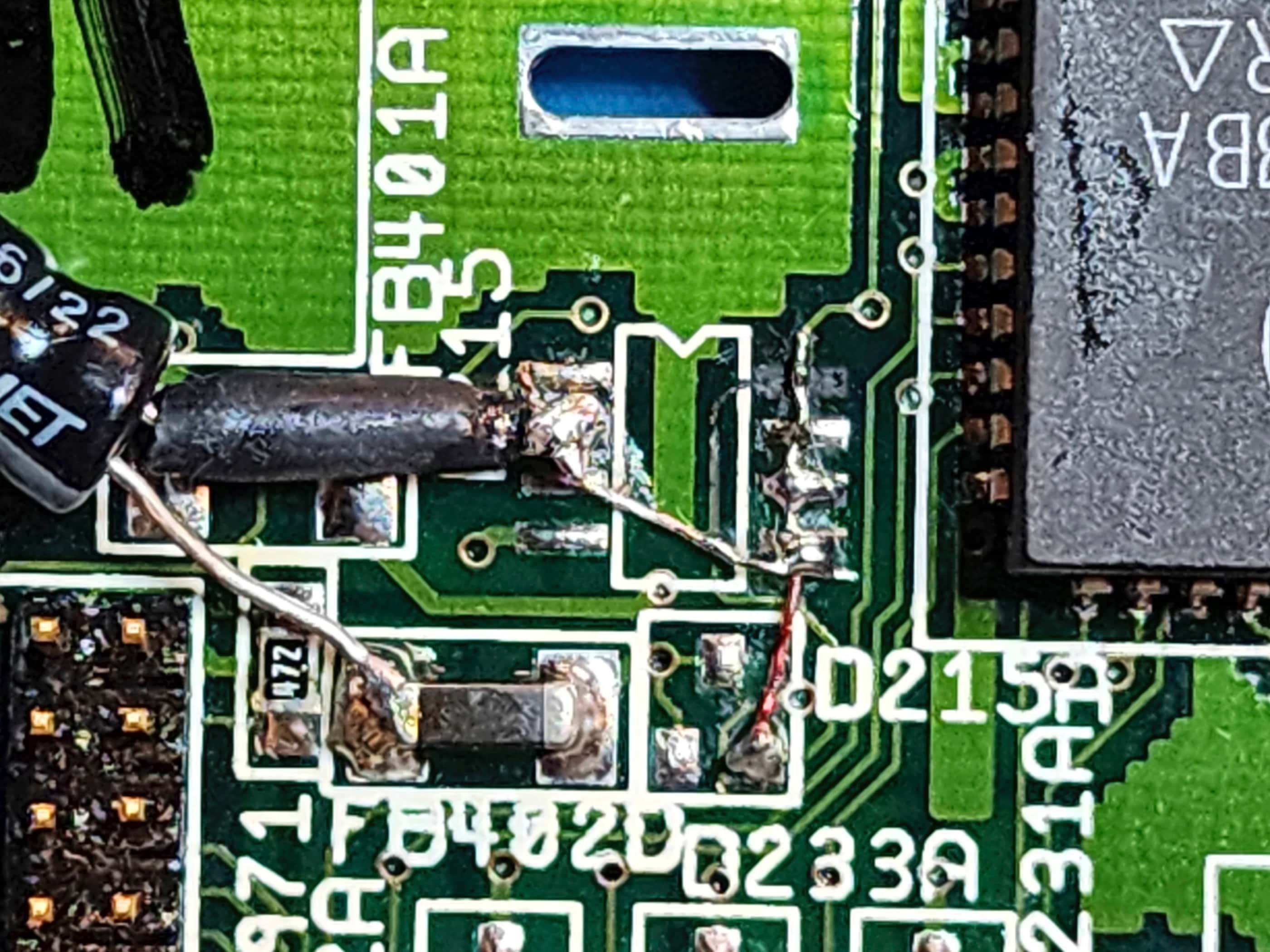
Anyway, the trace from pin 18 (VREF) on the Video DAC runs to a via and then to the anode of the capacitor in question on D215, before continuing to an unused pad on D215A. The capacitor’s cathode attached to the ferrite bead at FB402D. The problem was, the pad the anode was attached to on D215, was not strong enough to hold the size of the capacitor and during moving and storage, the anode arm of the capacitor had caused the pad lift and the trace to sheer. The cathode had also completely severed, but it made little difference to the overall solder weld at the ferrite bead.
I thought long and hard about how I could reattach the capacitor where it wouldn’t come loose again, along with how I could bridge the very tiny trace. As I studied D215, I noted that only 2 of the 8 pads were actually used (1 on each side), and so my plan was to run a bridge from the severed trace over the remaining three unused pads to D215A. I would then use one or two of the unused pads across from the bridge to secure the anode arm of the capacitor. From the third unused pad along the bridge, I would run a second bridge across to the anode.
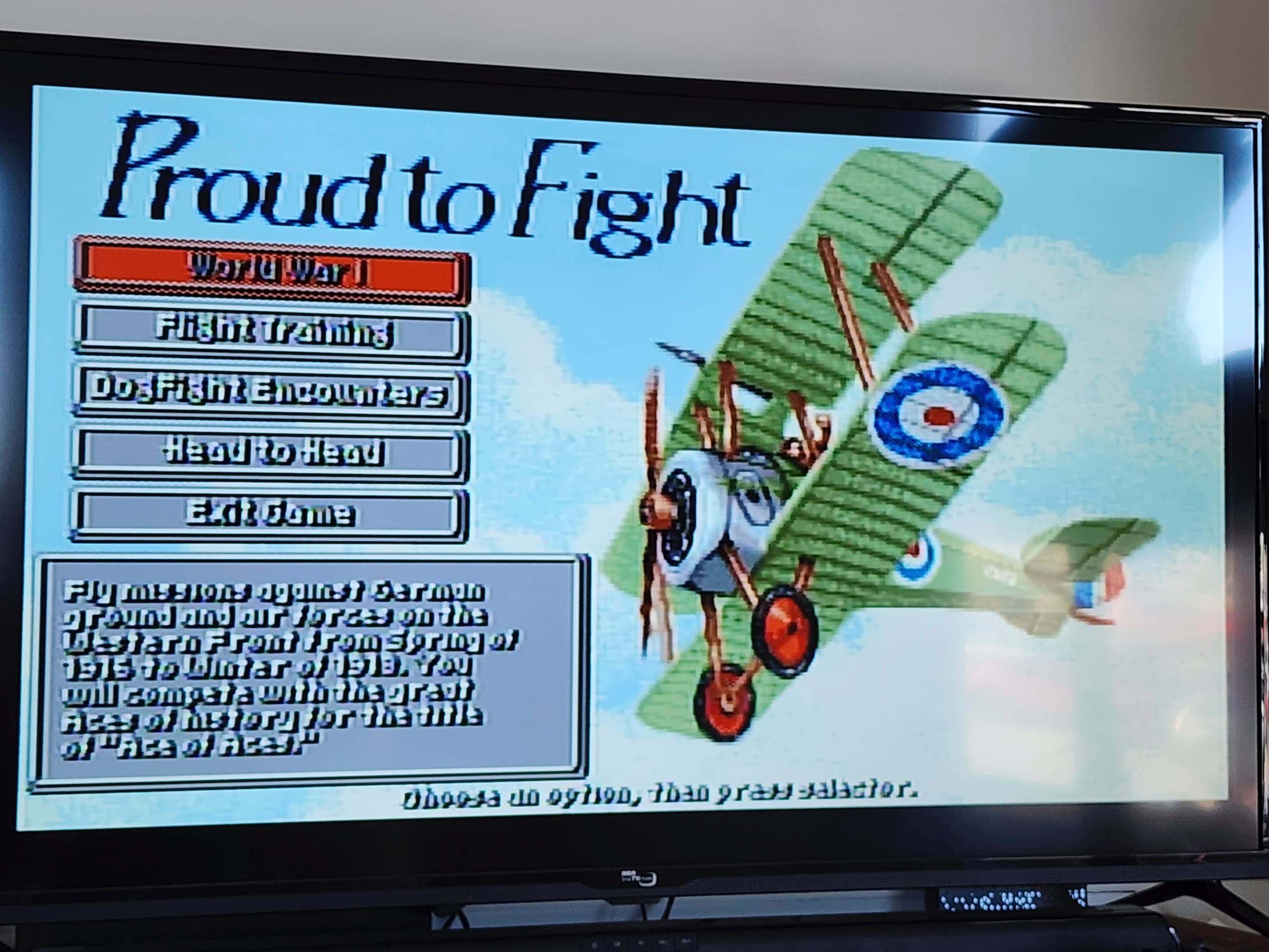
Using 30-gauge copper wire to make the bridges, my plan was successful and the new capacitor was firmly set into place and the trace was restored (Note: I initially forgot to cover the capacitor’s cathode leg with tubing to prevent shorting, but I went back later to add this). With the new power supply now in hand, I connected the board and fired it up for the first time. As I didn’t have an RGB connection, I was using the composite output which made all of my repairs crucial to the process. Anticipating something happening, I was disappointed that nothing happened…
I then tested the voltages and everything appeared normal, except for those on the CXA1145M video encoder, where I noted only 2.2v instead of 5v. I then correctly deduced that my bridge to the via underneath C409 was not perfect, so I removed and then reflowed the blob bridge. I reattached the capacitor and again powered the system on…
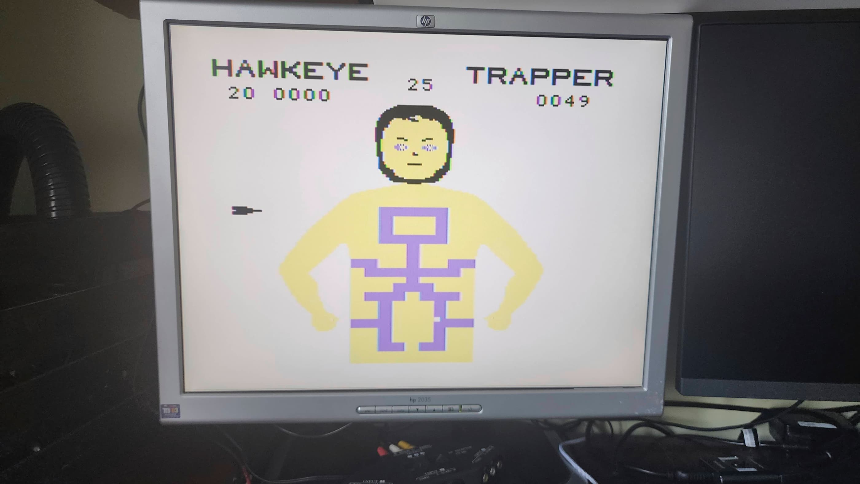
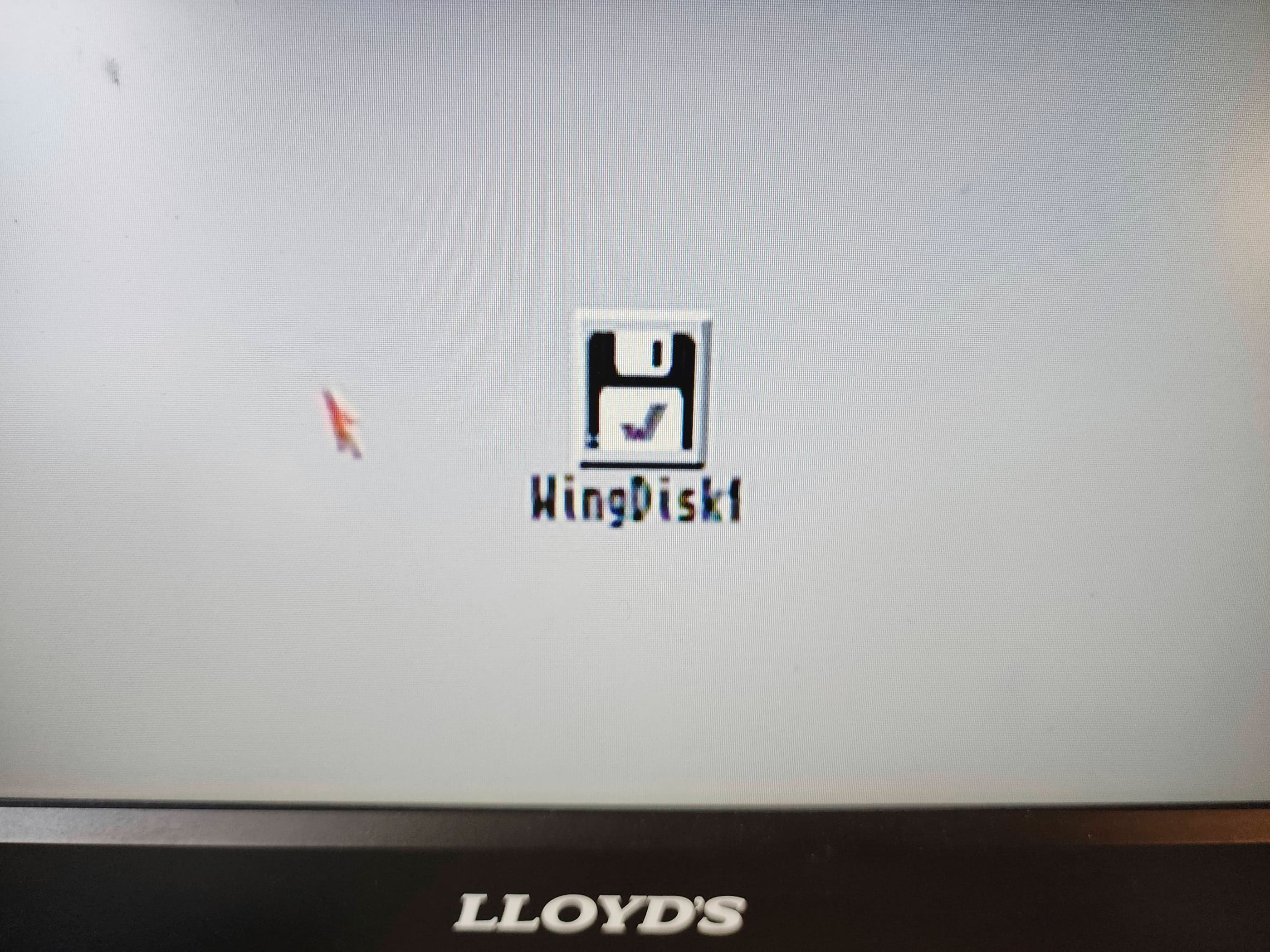
Success! I was greeted by a very clear start-up screen. I then turned my attention to the hard drive where I reattached a new, 10v 47μF tantalum SMD capacitor that I had ordered in from Mouser. I plugged the drive in and powered the system on again, and Viola! after all these years, the HDD fired up perfectly and booted right into Workbench. Amazing! 😀
Now that I was making progress, I then disassembled the internal 3.5” floppy, cleaning it thoroughly and replacing the single 25v 4.7μF SMD capacitor with a replacement hole-through electrolytic that I had on hand. I then reassembled the drive, hooked it up, and gave it a test. Success! It worked too. 😀
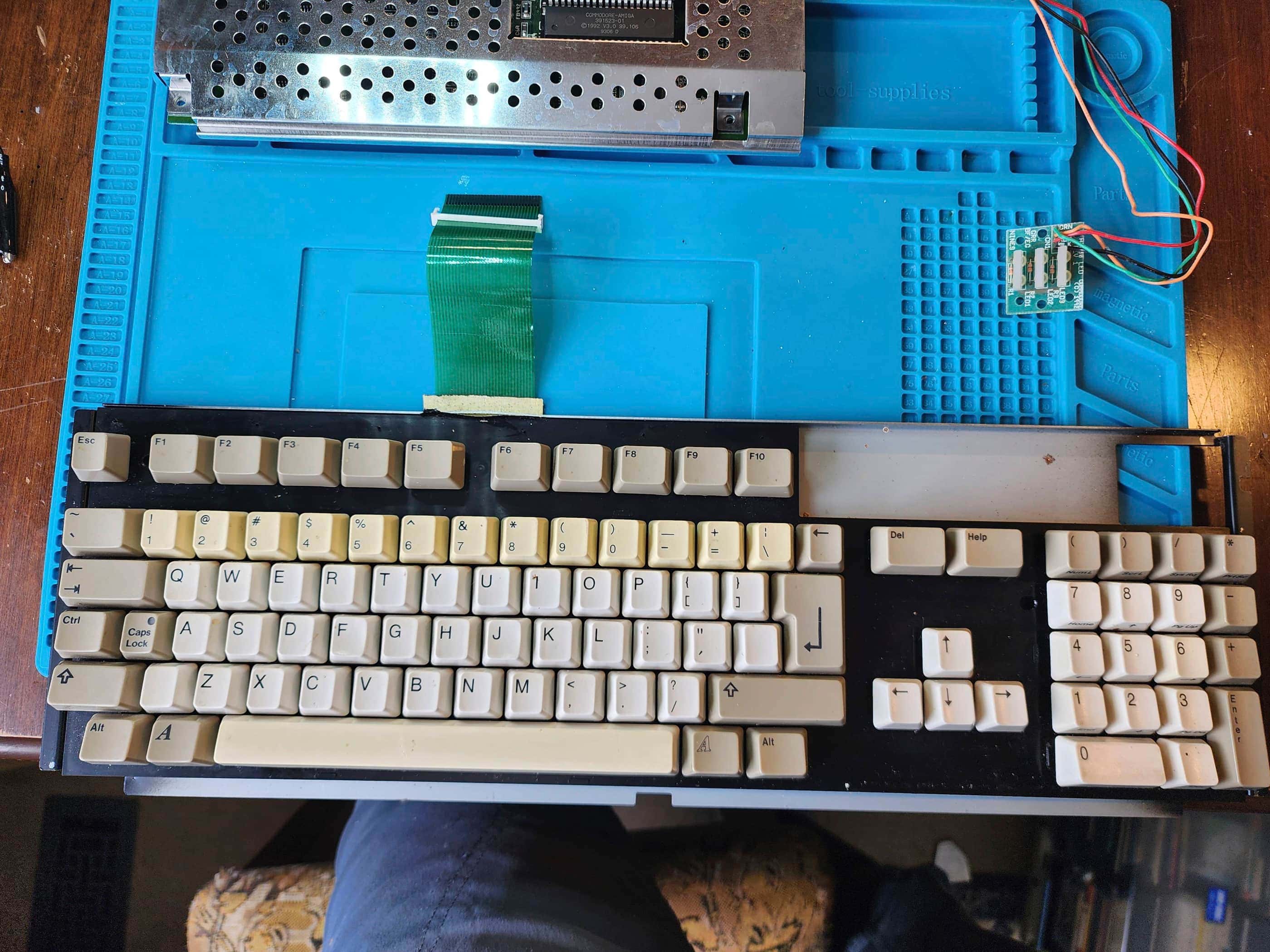
The final puzzle for me was the keyboard. At first it did not work and I spent time cleaning the ribbon cable along with the flex circuit membrane. When this didn’t fix the problem, I checked the continuity of each pin on the board along with the voltage on U13 – the keyboard MPU. Everything checked out. That’s when I realized that the white clip that holds the ribbon cable in place on the board, has a front and a back that is hardly noticeable at first glance. When I flipped the clip around and powered the system on, the keyboard worked perfectly.
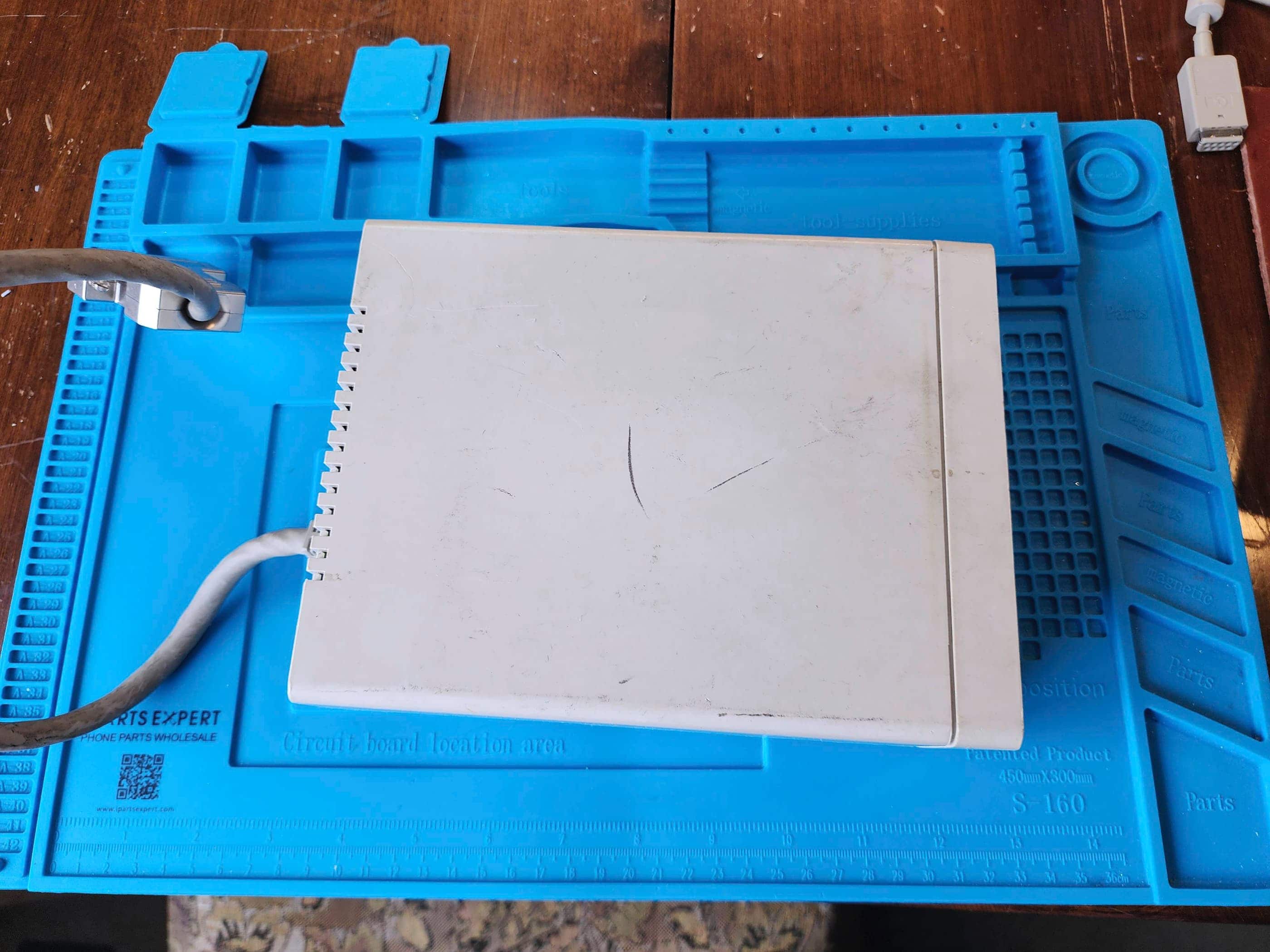
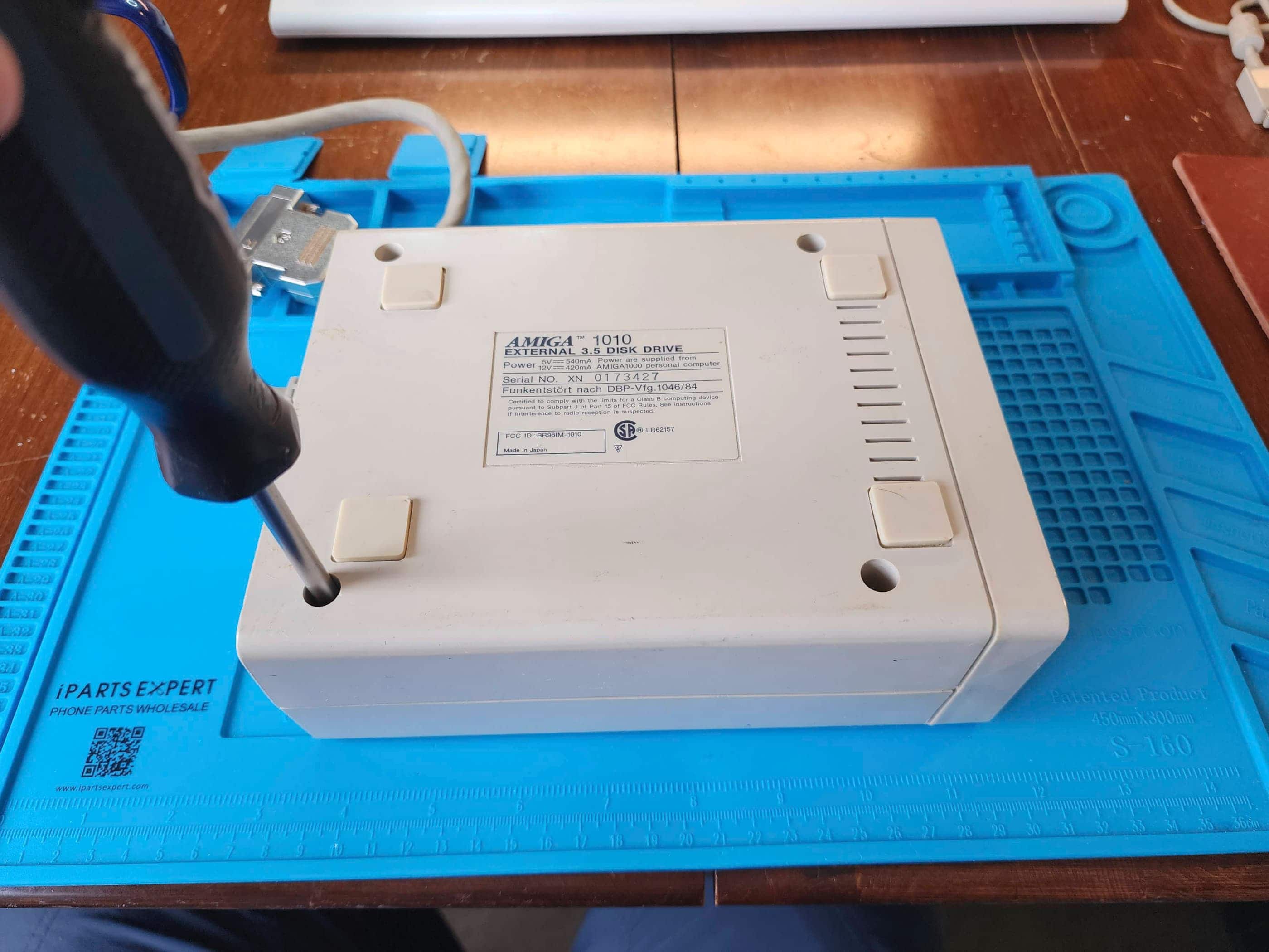
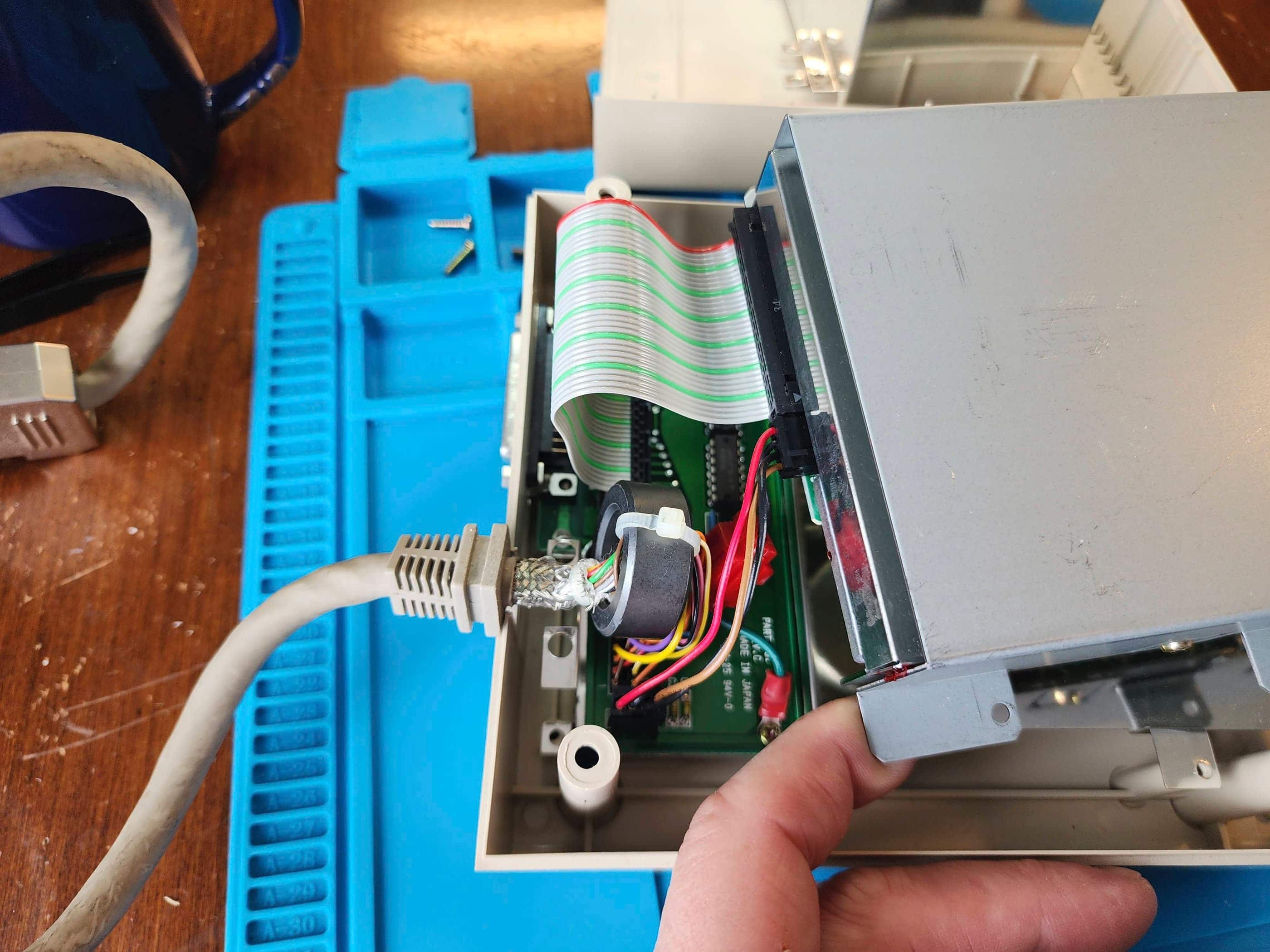
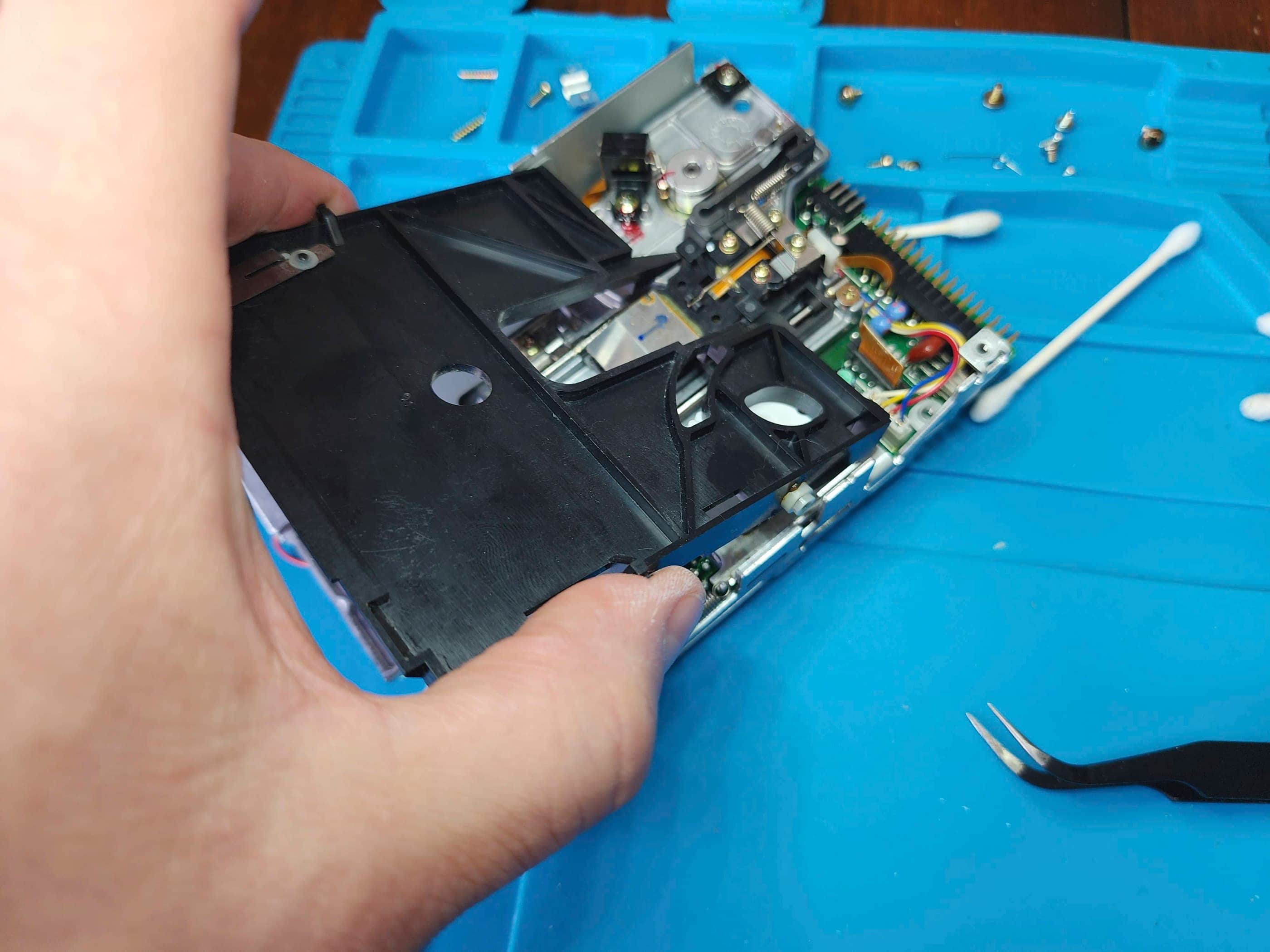
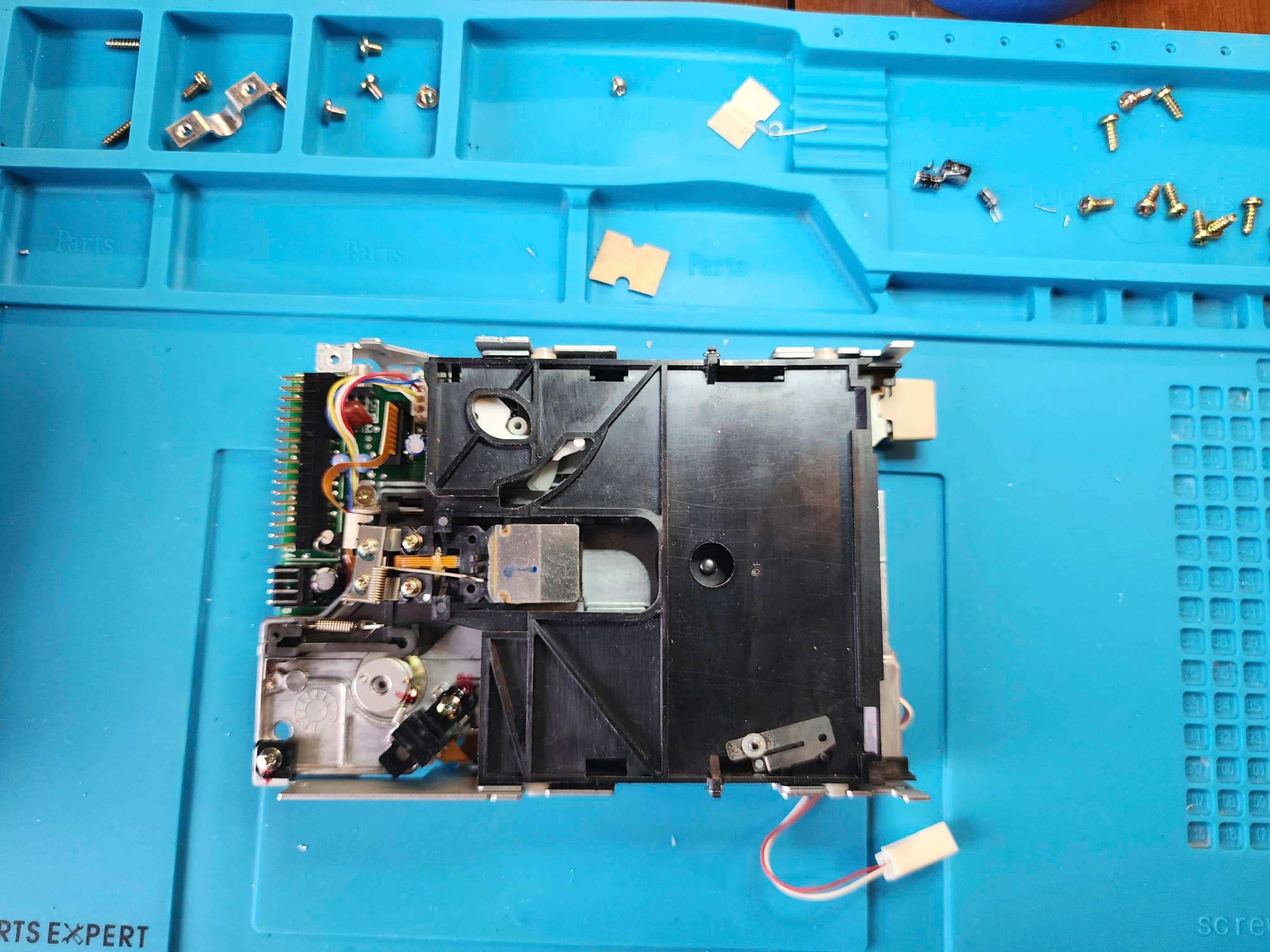
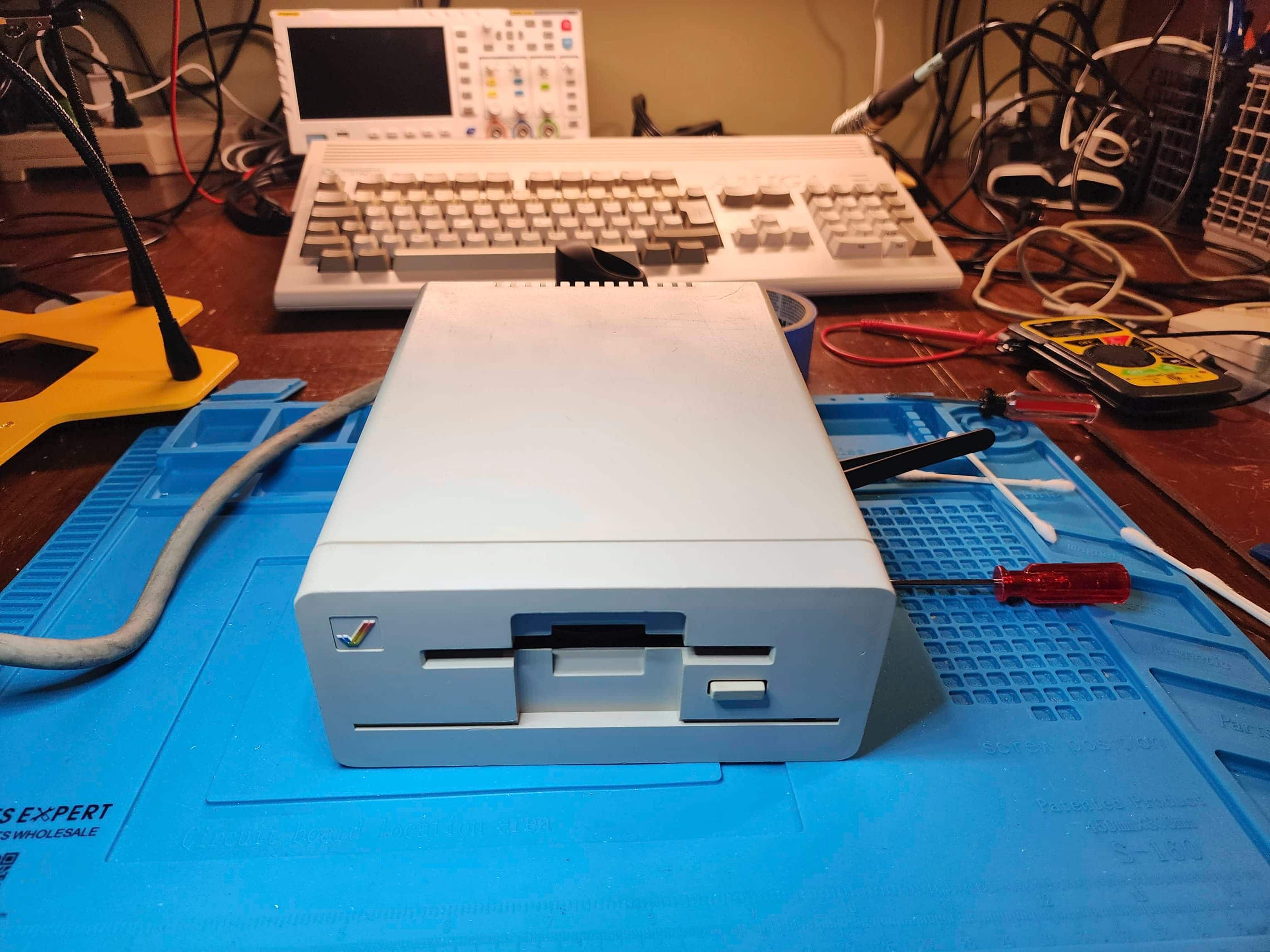
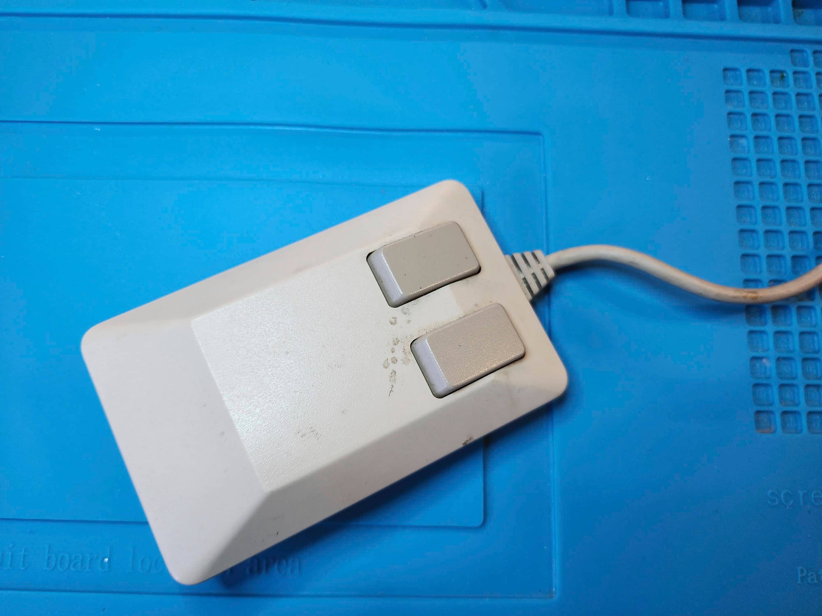
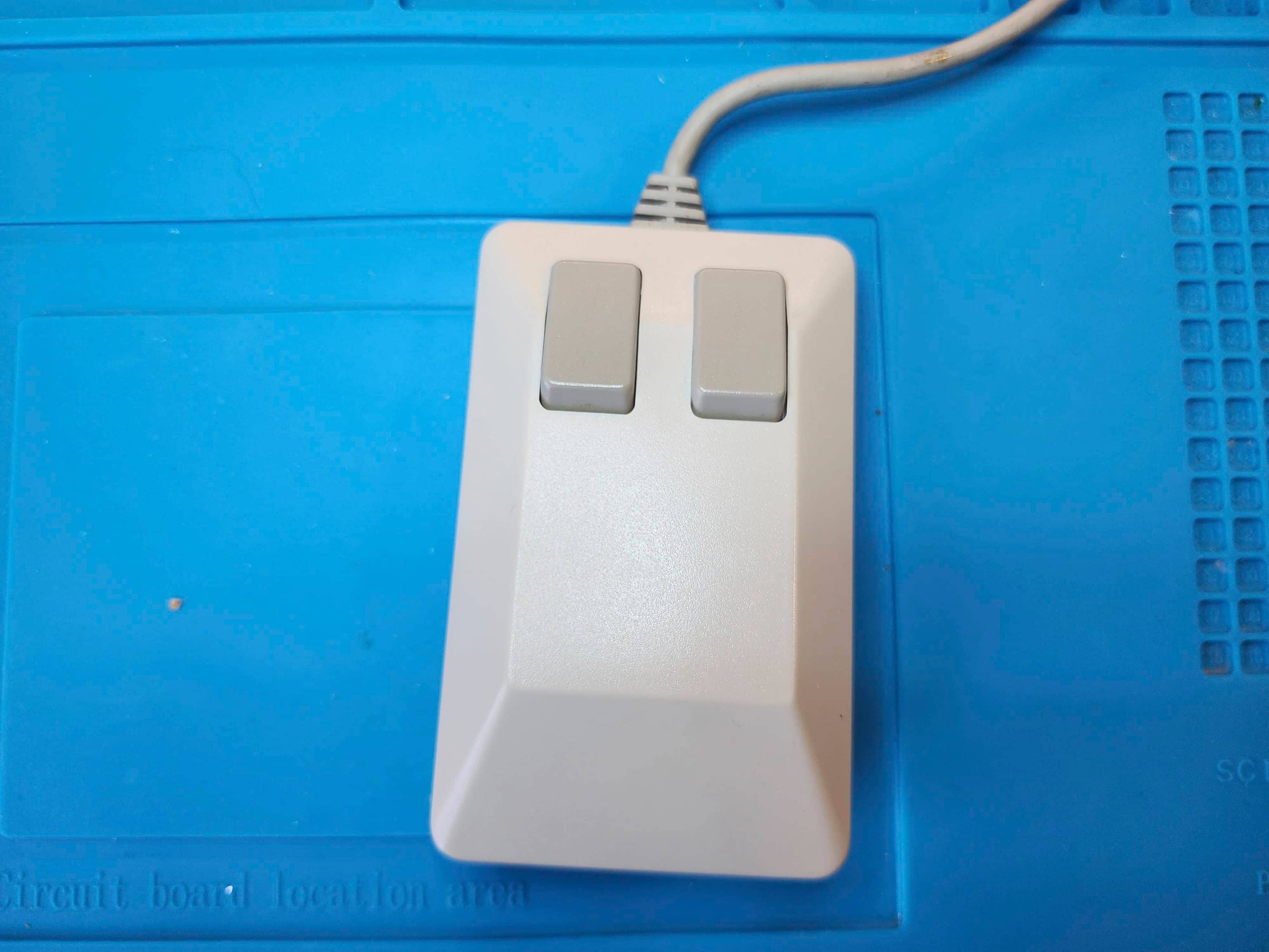
After reassembling the A1200, I then worked on two accessories: 1) the Amiga 1010 external floppy drive; and 2) the Amiga tank mouse. First, I disassembled the 1010 drive (it was a Newtronics version) and replaced the three hole-through capacitors (6.3v 47μF 16v 47μF, and a 16v 4.7μF). The third capacitor required most of the drive’s mechanism to be removed to get to, but everything went smoothly and after a thorough cleaning it was soon back together. Next, I took apart and cleaned the tank mouse, and in the process, replaced the single hole-through 10v 47μF capacitor. This was a quick task.
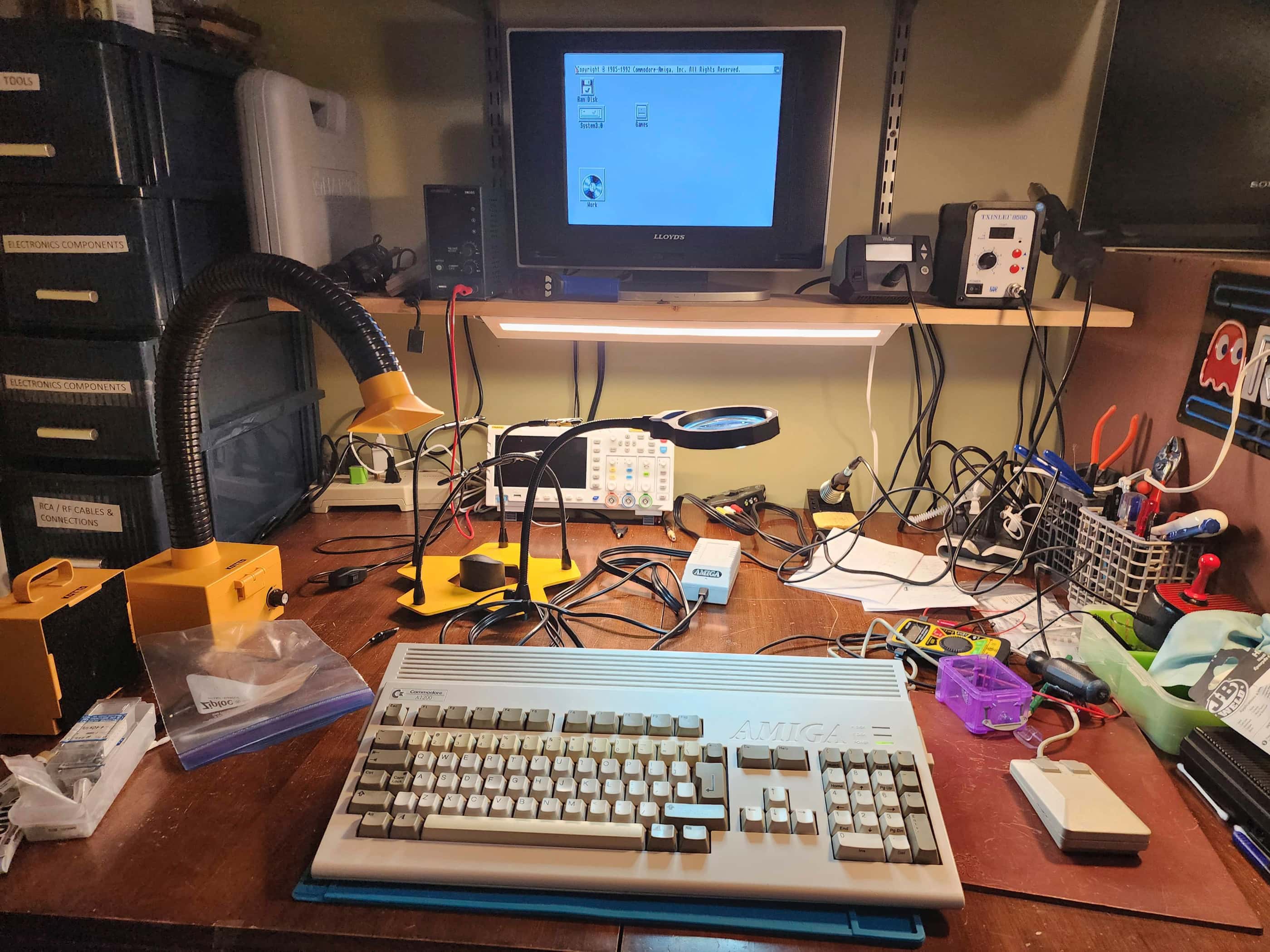
With everything back together, I tested the machine along with drives for quite some time, noting that everything worked as it should. Boy, did the memories flood back while I was doing this and I think I’m as excited about seeing the Amiga up and going as my BIL is. 😁 I’m still impressed that the HDD worked perfectly and everything that he had put on it back in the 90s was still there, including his old game saves. Of the four boxes of floppy discs, some worked, but others did not, as age has started to take its toll. Nonetheless, this was a very special project to work on!
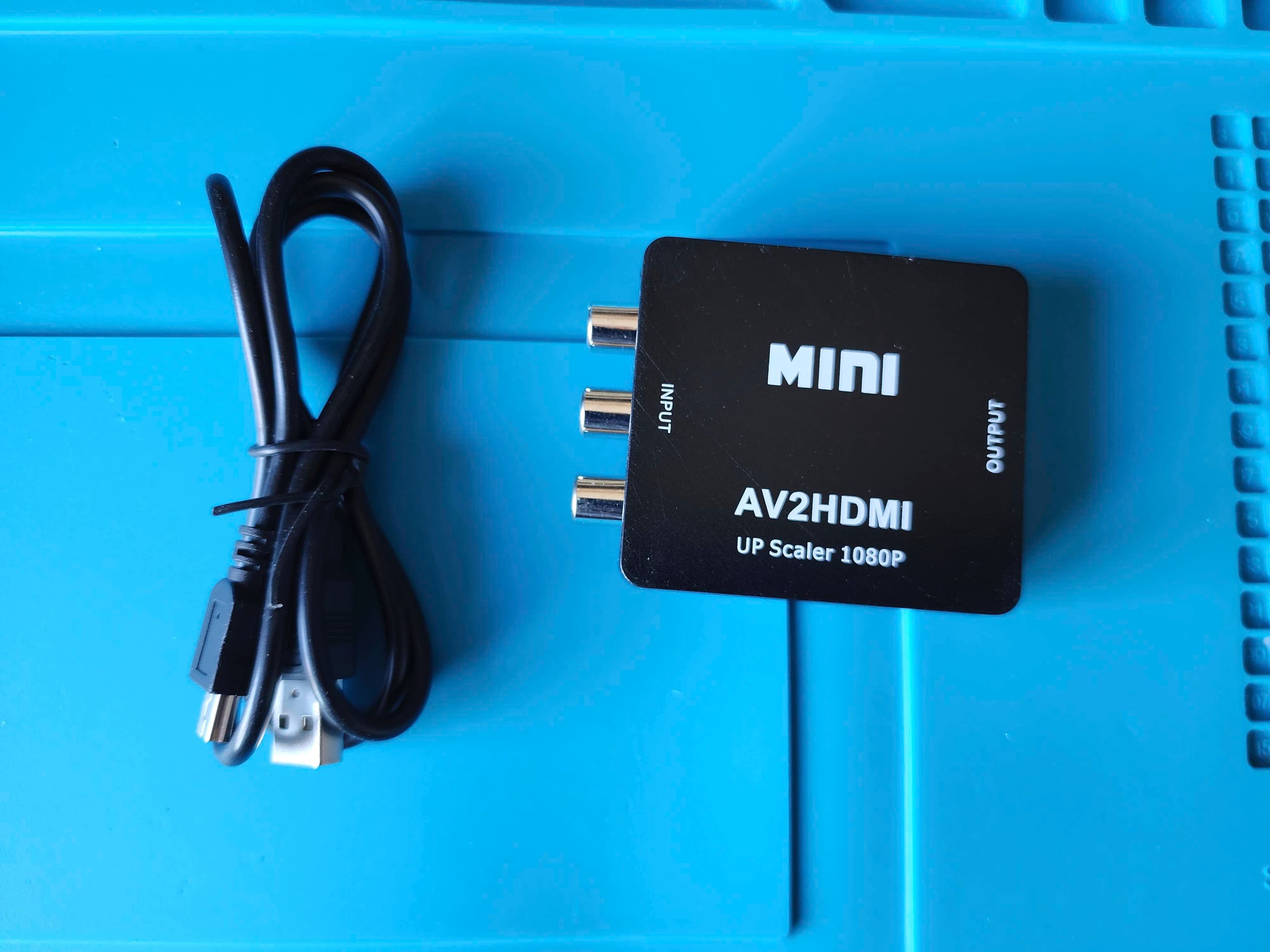
Parts & Products Used: 99% isopropyl alcohol; Chemical Guys Natural Shine; Amiga PCB electrolytic capacitors (radial) – 10V 1000μF (2), 16v 470μF (2), 50v 2.2μF (1); electrolytic capacitors (SMD) – 6.3v 100 μF (4), 16v 47μF (2), 35v 10μF (3), 35v 22μF (5); WD Tibit 60GB HDD tantalum capacitors (SMD) – 10v 47μF (1); 3.5 Internal Floppy Drive (original was an SMD but I replaced it with a radial capacitor) – 25v 4.7μF(1); Amiga 1010 External 3.5″ Floppy Drive (Newtech) electrolytic capacitors (radial) – 6.3v 47μF (1), 16v 47μF (1), 16v 4.7μF (1); Power Board electrolytic capacitors (radial) – 16v 470μF (1), 16v 3300μF (1), 25v 220μF (3), 50v 1μF (2), 50v 4.7μF (1), 50v 47μF (1), 200v 200μF (1), 450v 1μF (1); 26 gauge wire; 30 gauge coated copper wire; Keelog Amiga power supply; ABLEWE RCA to HDMI Converter; JB Weld Heat Resistant Epoxy
You must be logged in to post a comment.