
Second Generation (1976 – 1992)

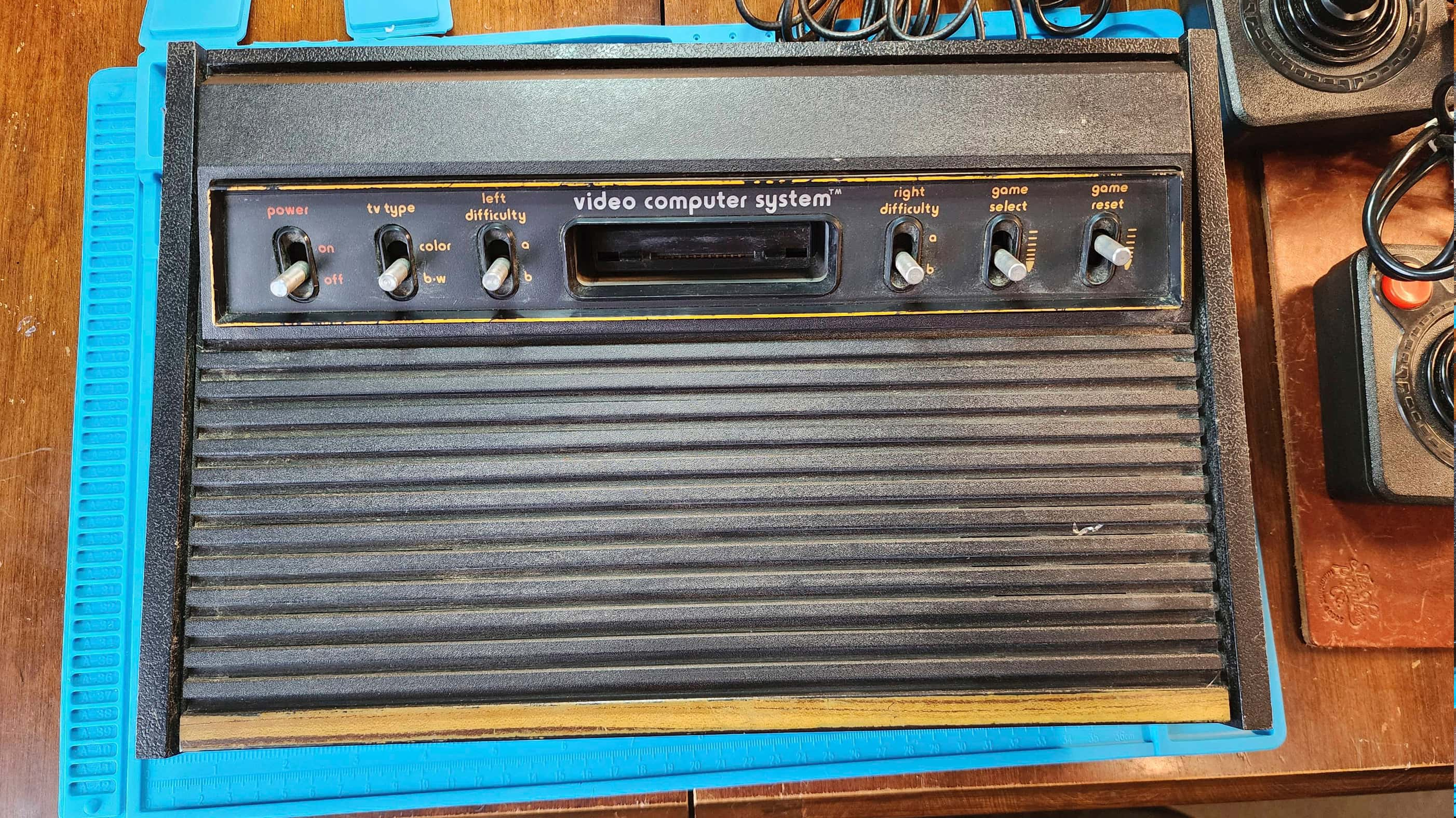
Atari Video Computer System (VCS) “Heavy Sixer” (CX-2600)
Years (1977 – 1978)
Interesting Fact: The Atari VCS “Heavy Sixer” was the first model of the popular Atari 2600 console series. (source) Code named “Stella” while in development (source) and manufactured in Sunnyvale California, the first production run of the CX2600 console in 1977 differed from later models by virtue of its design. It had a thick ½” plastic bottom that was coupled with thick side mouldings. When combined with the weight of the robust aluminum RF shielding, it made the console much heavier than subsequent generations; hence, the moniker, “Heavy Sixer”. (source) Aside from weighing 1.2lbs more than the “Light Sixer” (source), it is also distinguished by a curved moulding on the front of the console where the woodgrain meets the black polystyrene plastic. Almost all “Heavy Sixers” were manufactured in Sunnyvale before production was moved to Hong Kong in 1979. (source)
That the “Heavy Sixers” were only produced from 1977-1978 means there were a limited number produced, though the actual number is not known. Steve Fulton notes that in the 1977-1978 fiscal year, Atari had sold most of the 400,000 units that had been manufactured (source); however, the fiscal year ended in June 1978 and heavies were still produced through the fall of 1978, so a healthy guess might be to double that number. Atari Age has an ongoing thread documenting serial numbers and some posters have speculated production numbers based on this information. Regardless, the “Heavy Sixer” is a relatively rare find for any collector.
Condition When Acquired: Fully Functional
Current Condition: Fully Functional


Project Details: I’ve wanted a “Heavy Sixer” for a very long time. The problem is, they’re hard to find and when you do find one, they’re usually north of $300. That changed when I found this one for a reasonable price.
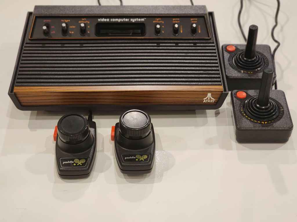
Overall, the console was in decent shape, though the orange trim around the switches had started to come off. It also came with CX-40 joysticks that may or may not have been original to the console. I say this because the CX-10s were the original joysticks that came with “Heavy Sixers”, but later production of heavies also came with the CX-40. I might keep my eye open for some decently priced CX-10s and pair these up with the console in the future, but for now, I’m good with finally having the console itself.
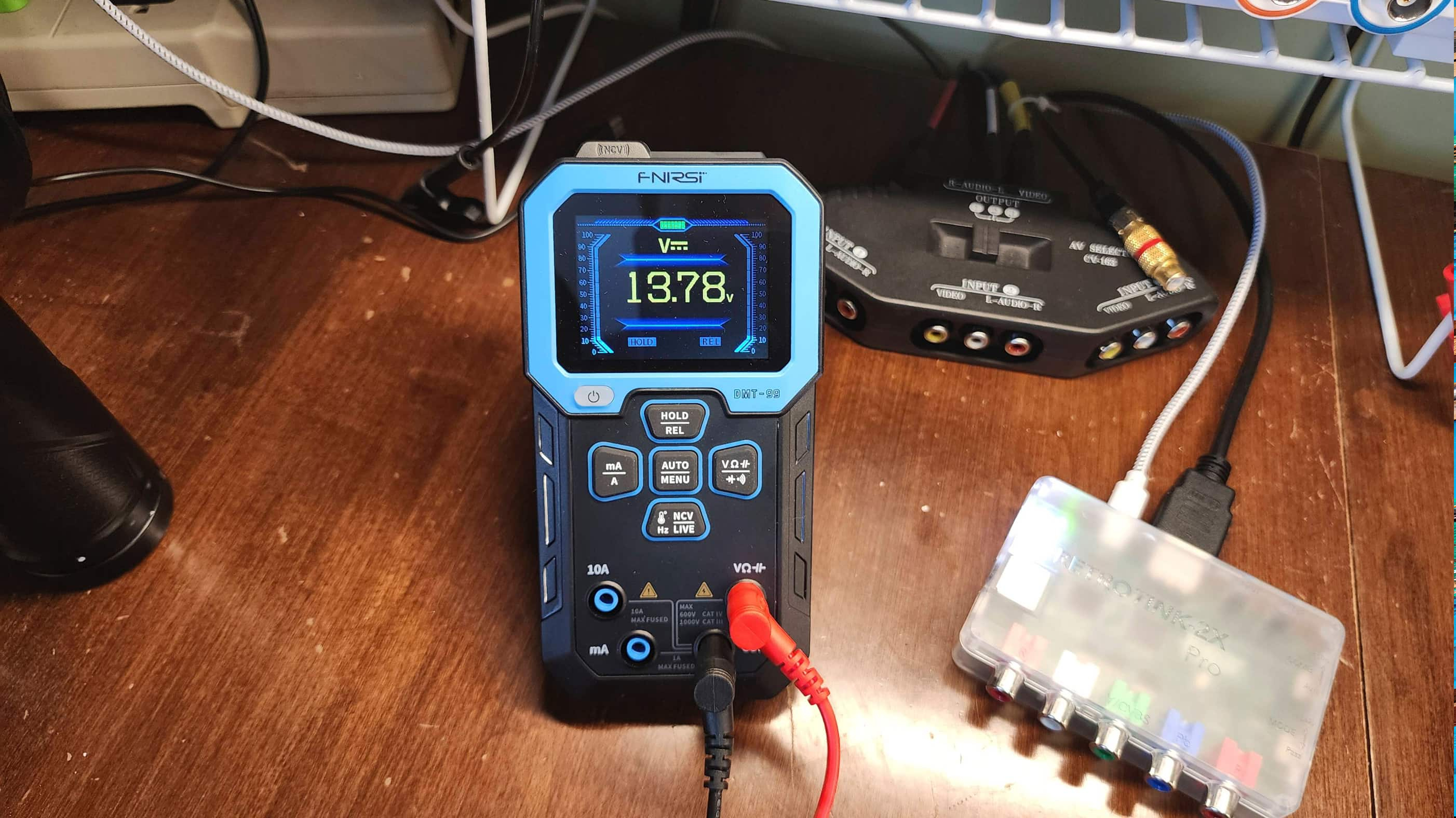
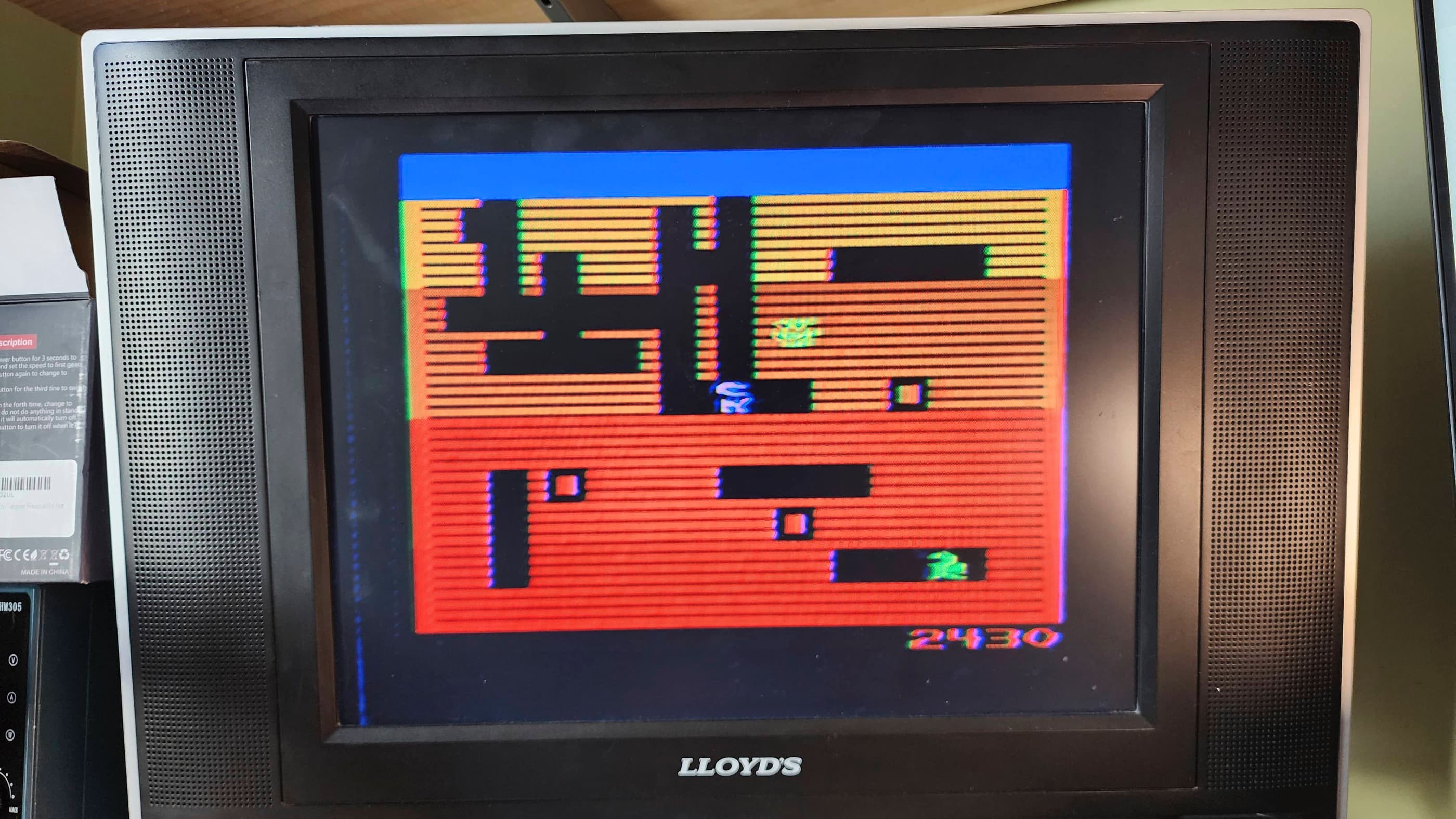
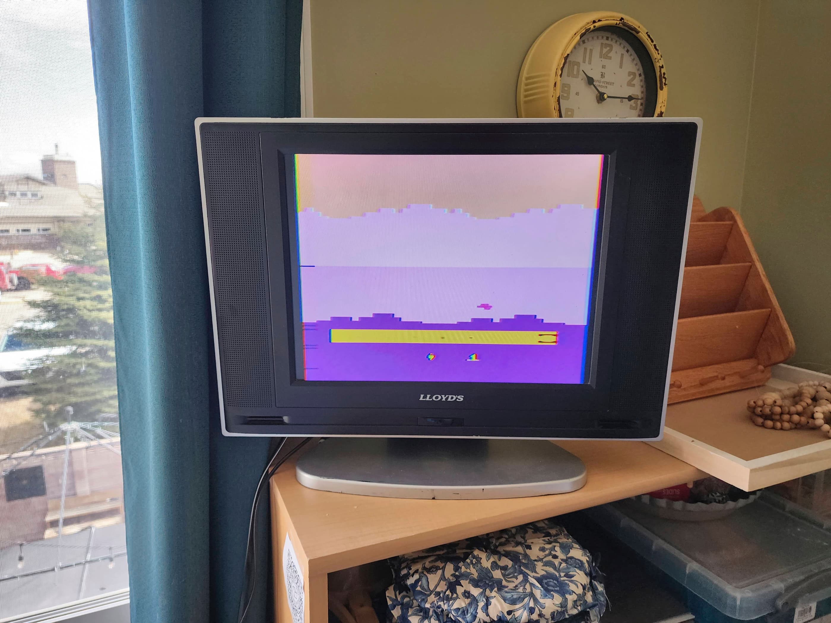
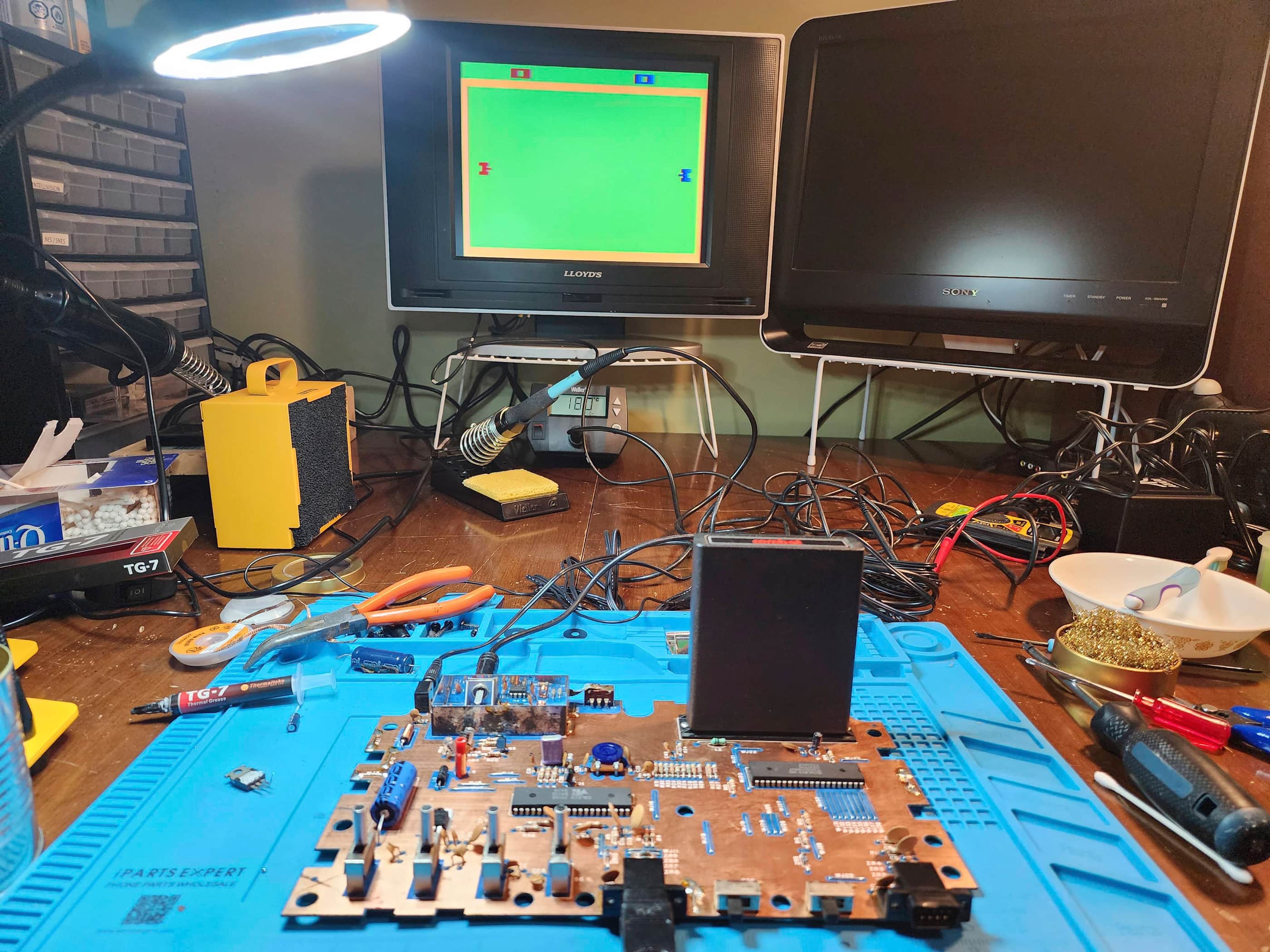
After receiving the console, the first thing that I did was check the voltage of the 9V power adapter. Seeing a healthy unloaded 13.78 V meant that I could safely power on the unit and I was pleased to see Dig Dug come to life on my screen.
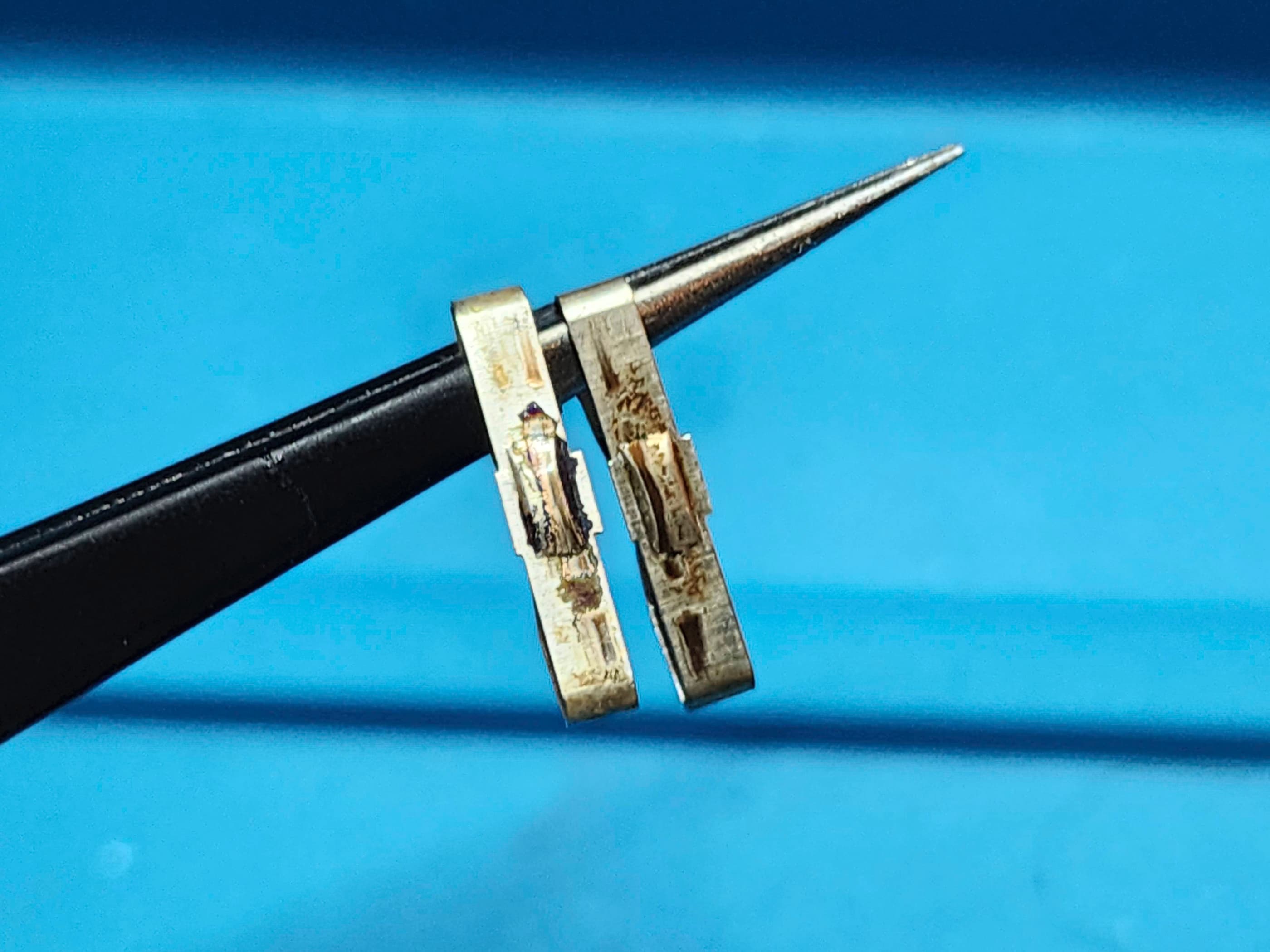
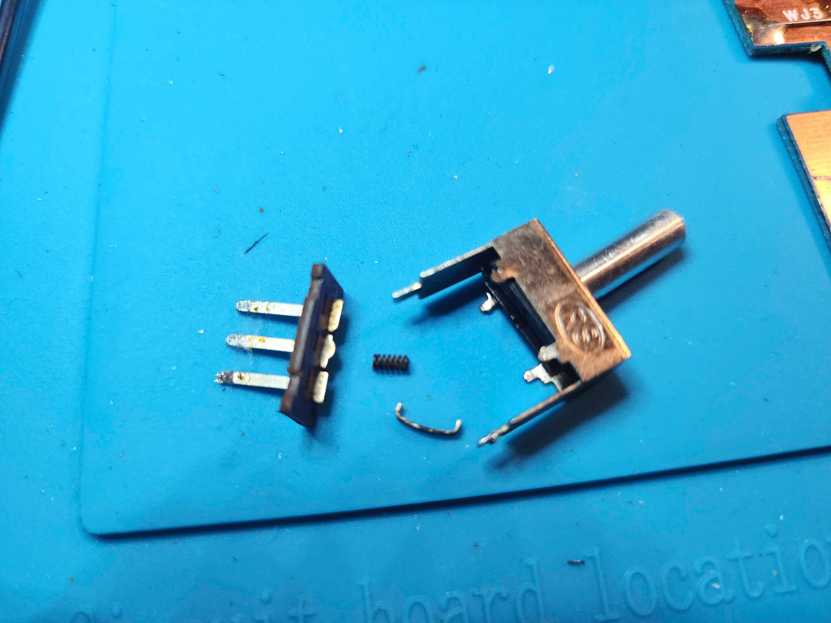
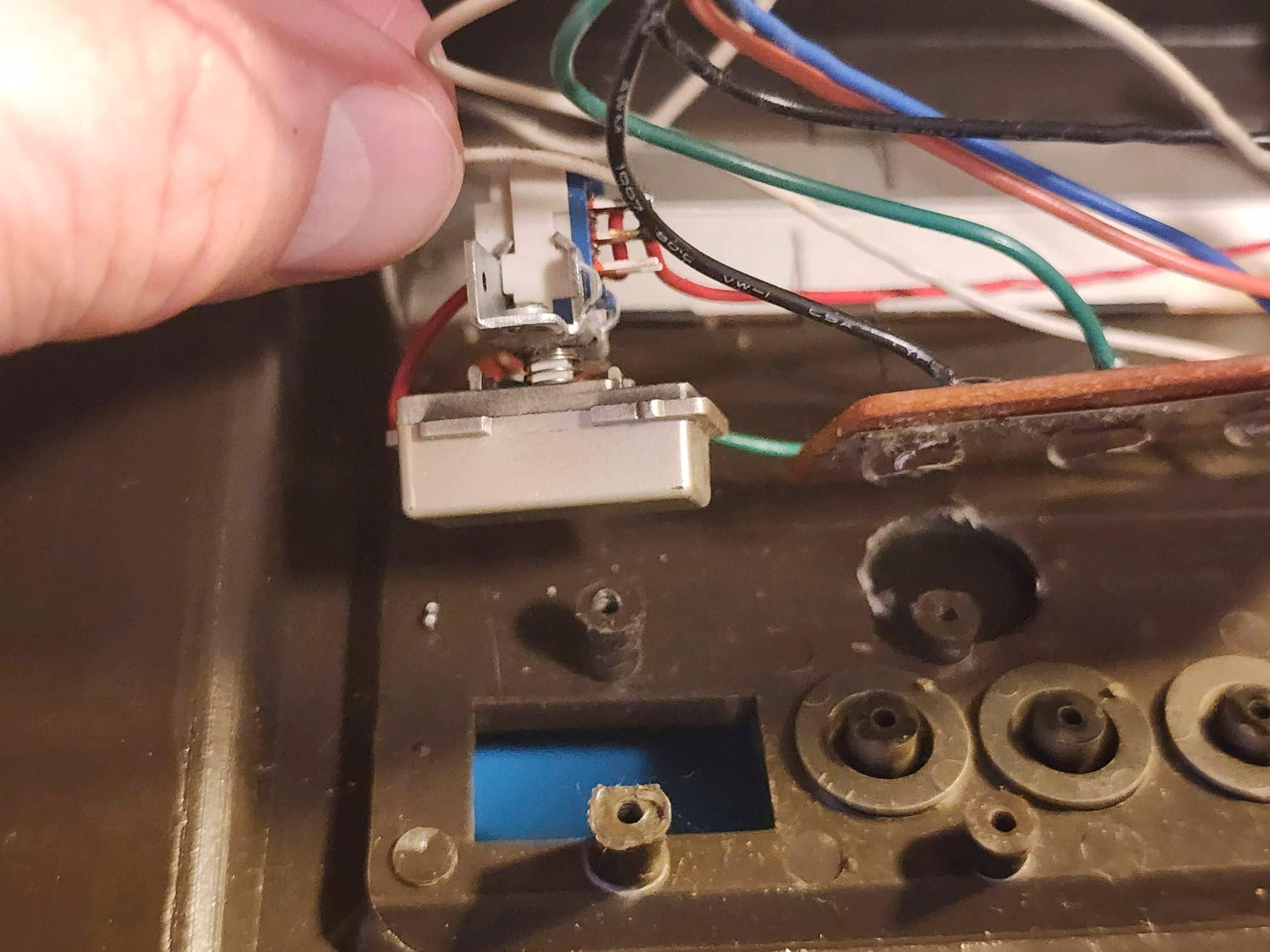
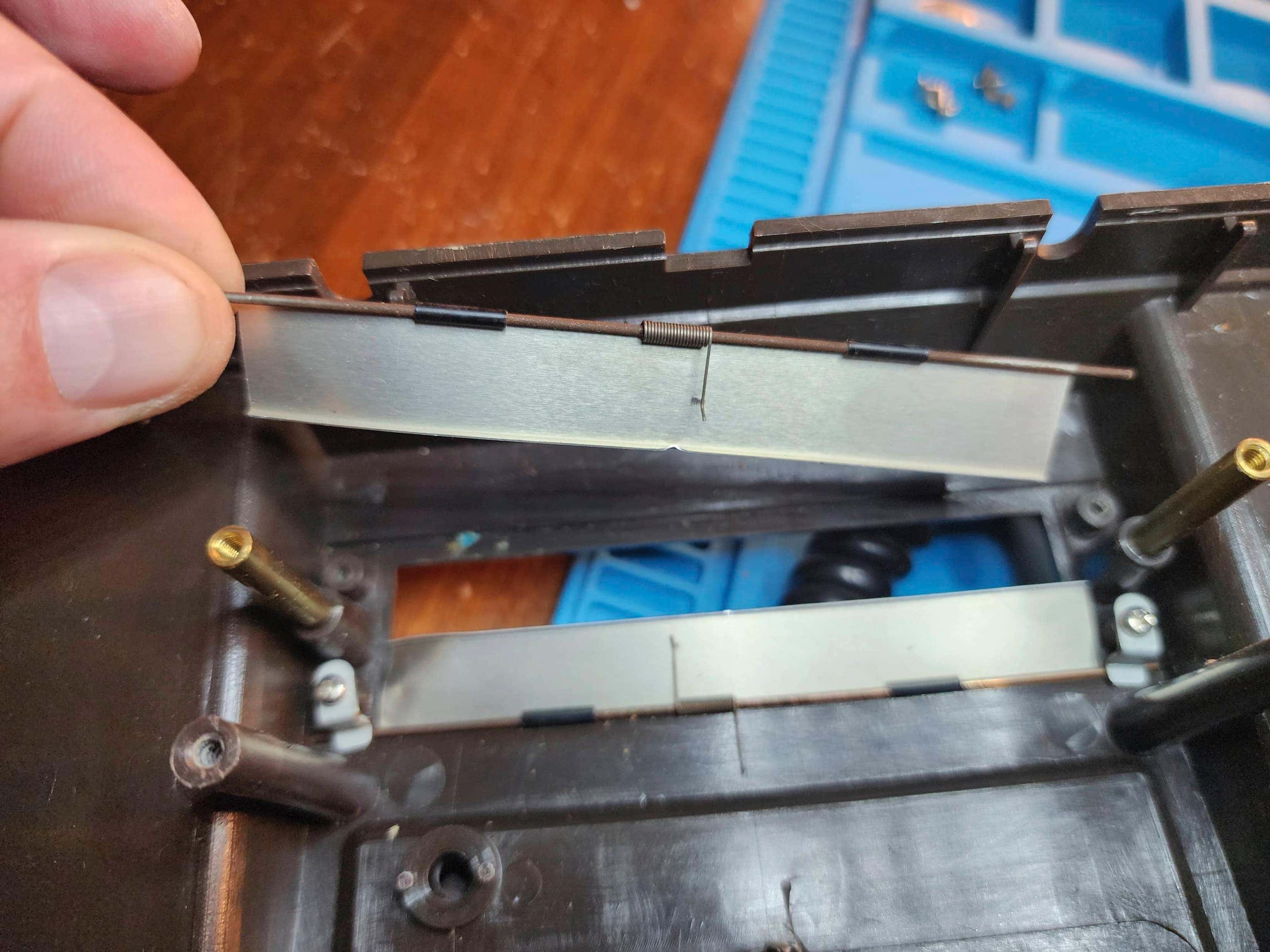
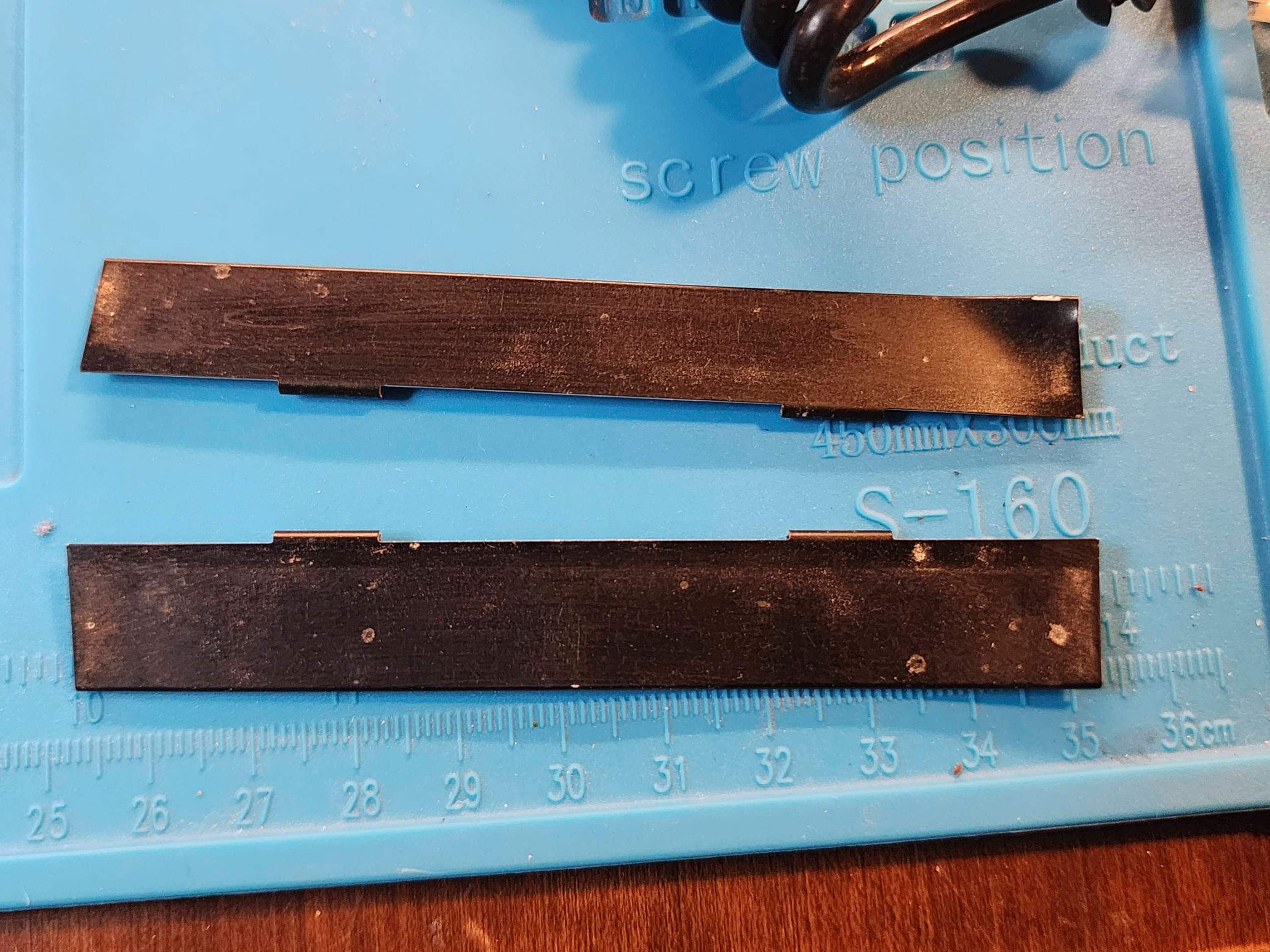
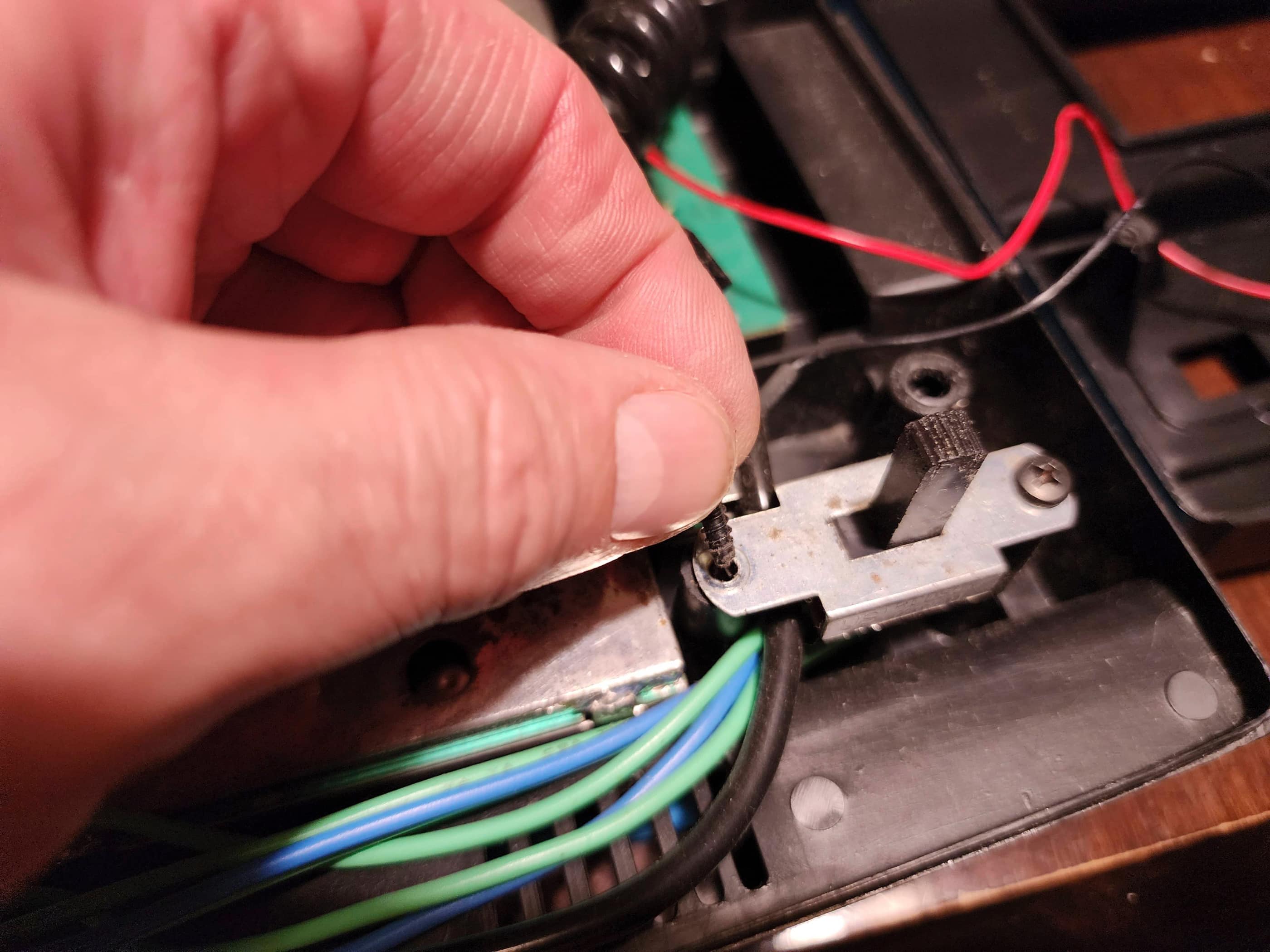
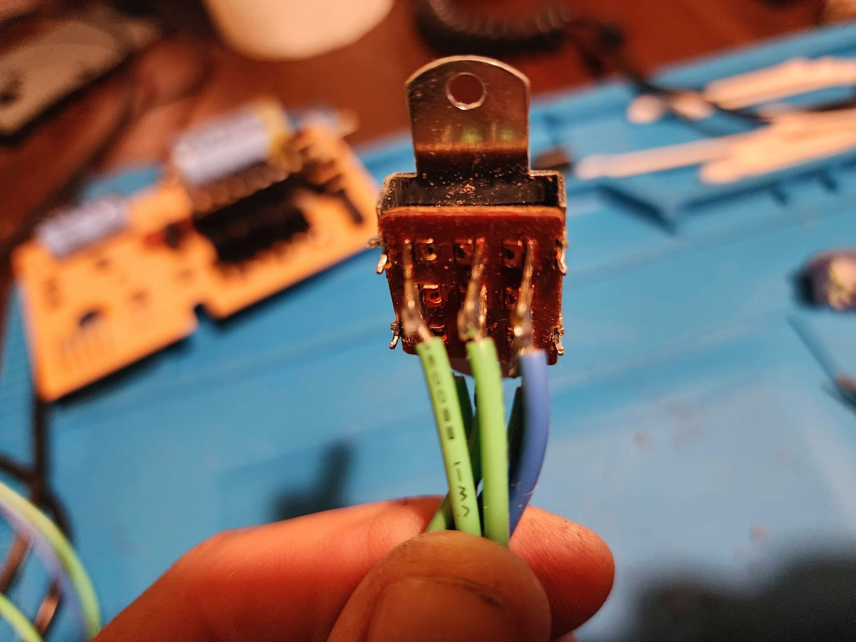
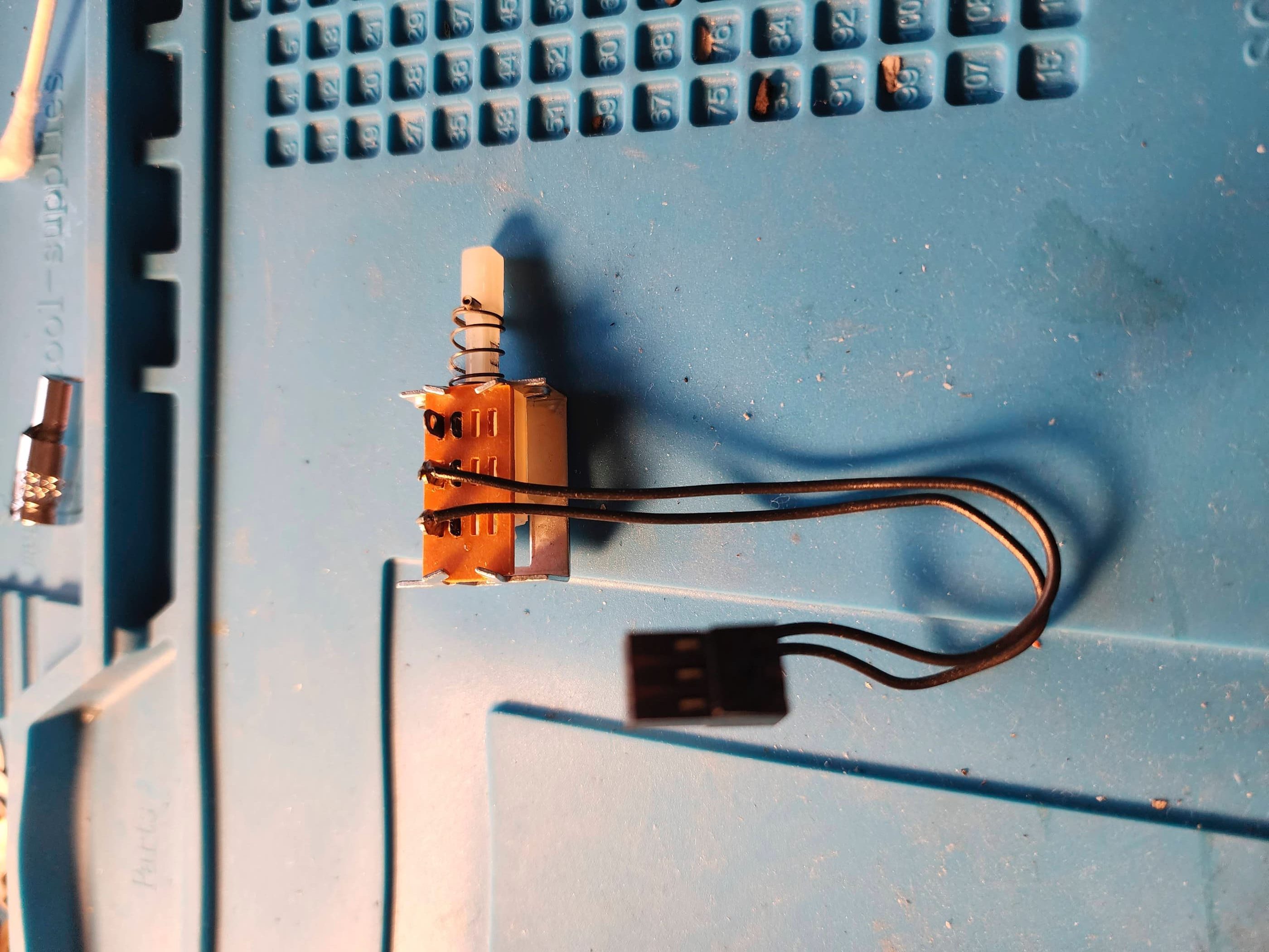
One issue I did notice right off the bat, was the broken spring on the Game Select toggle switch. I also noted that the unit needed a colour adjustment, but other than these two issues, it worked perfectly. Of course, as it had obviously been in storage for many years, it was quite dirty and needed a little TLC.
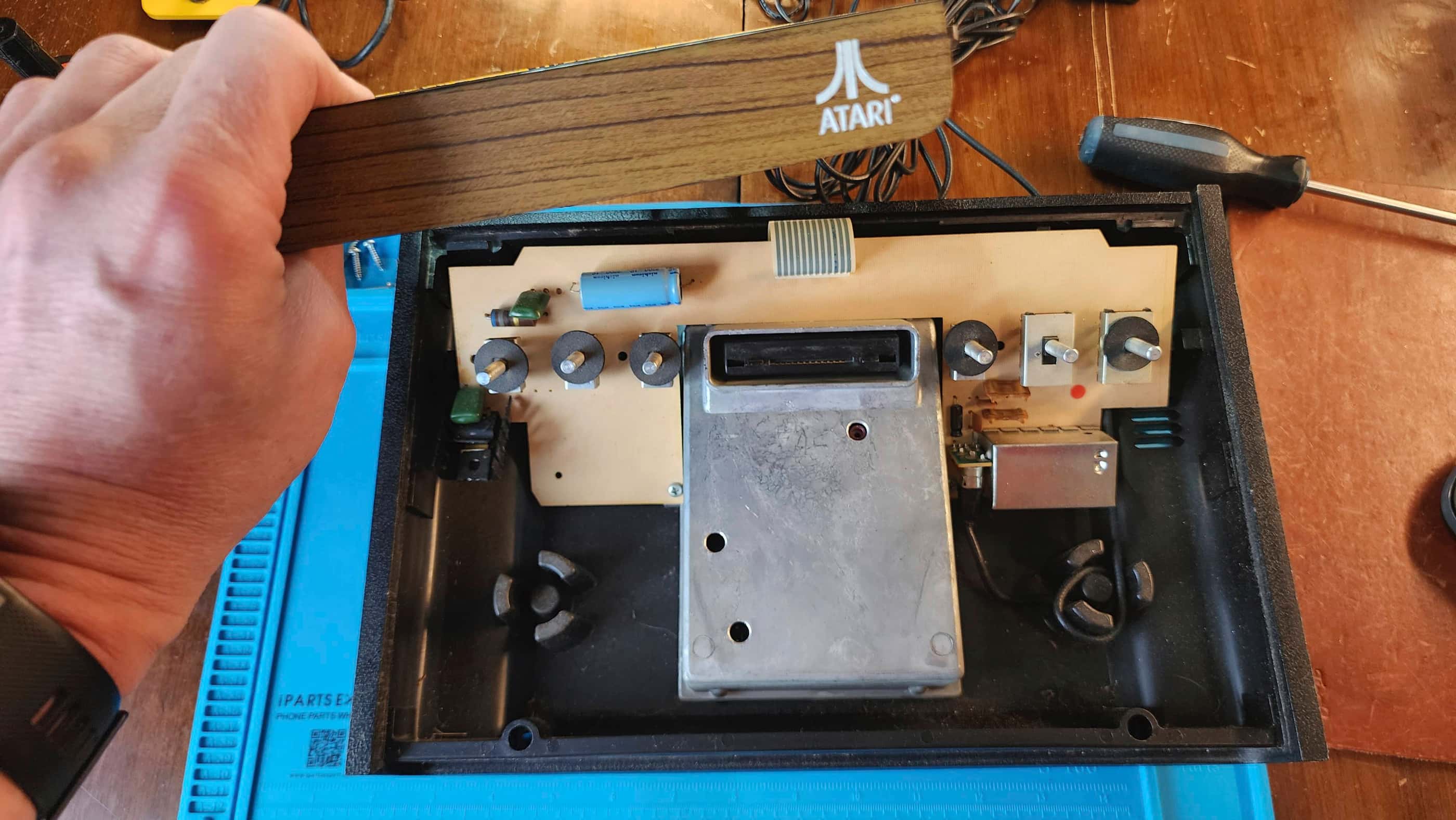
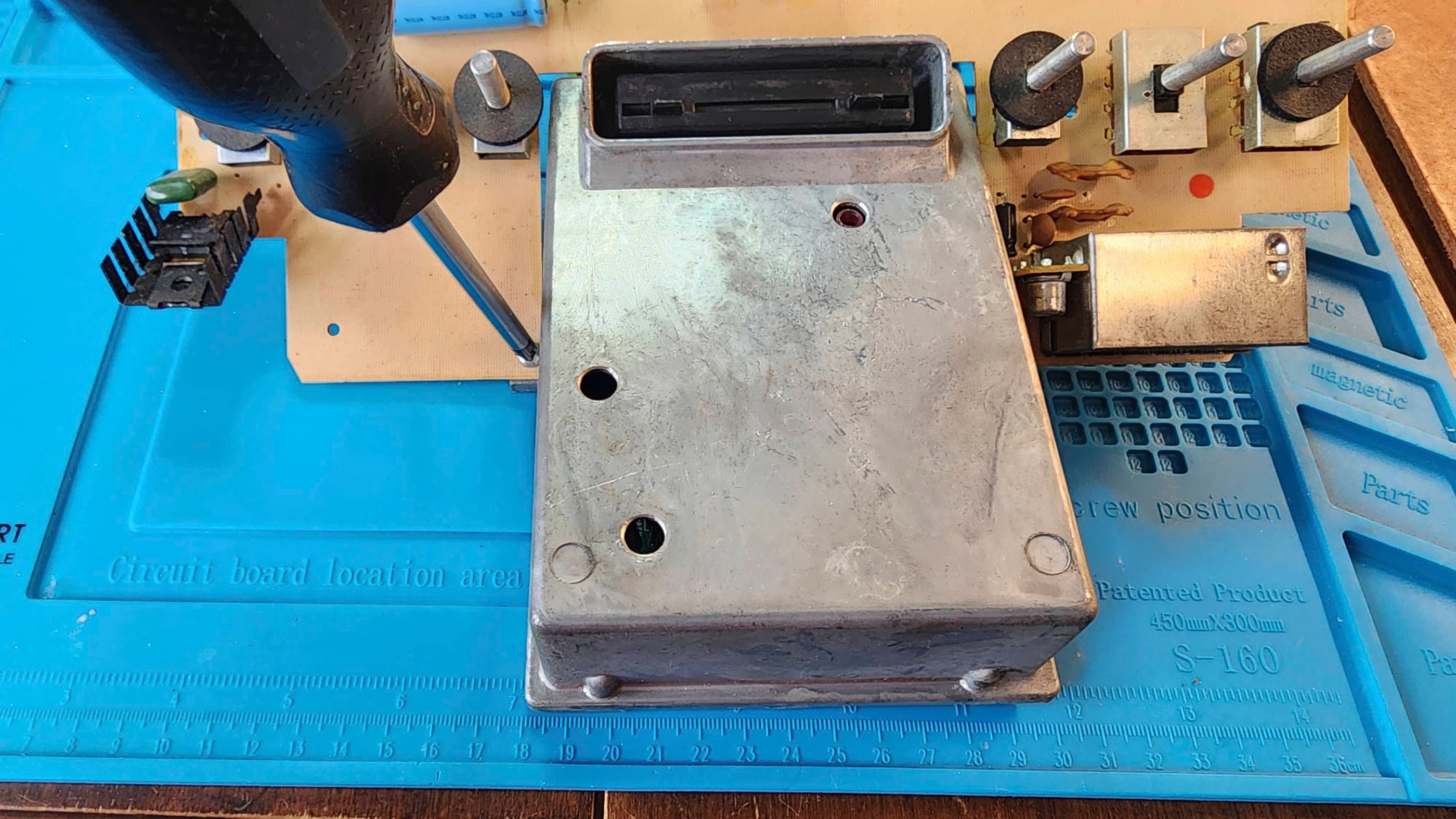
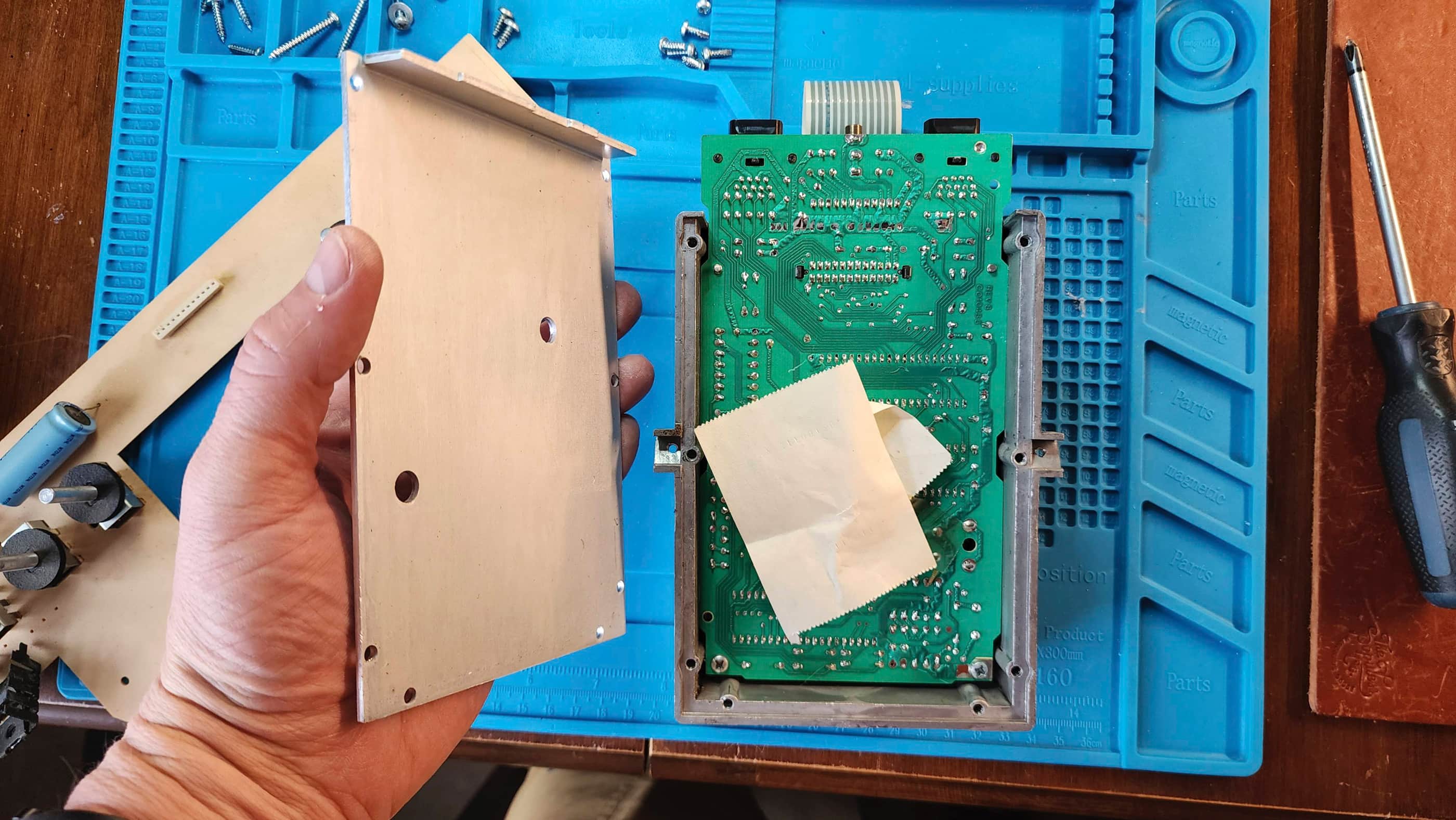
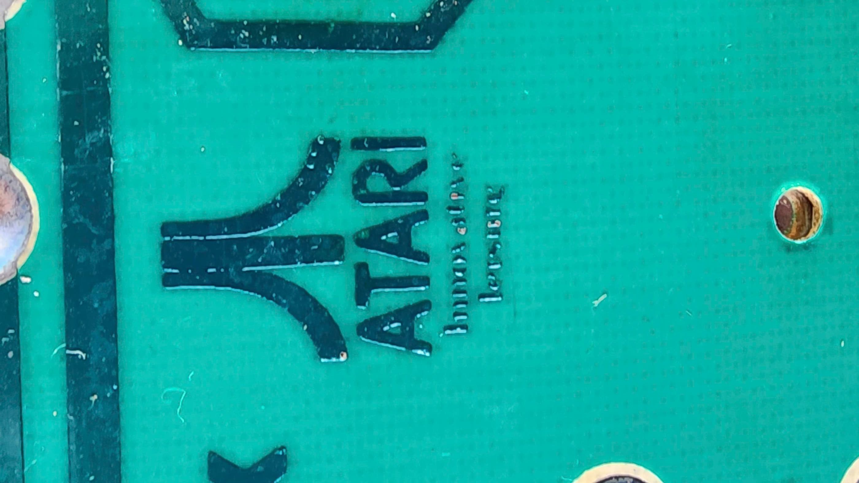
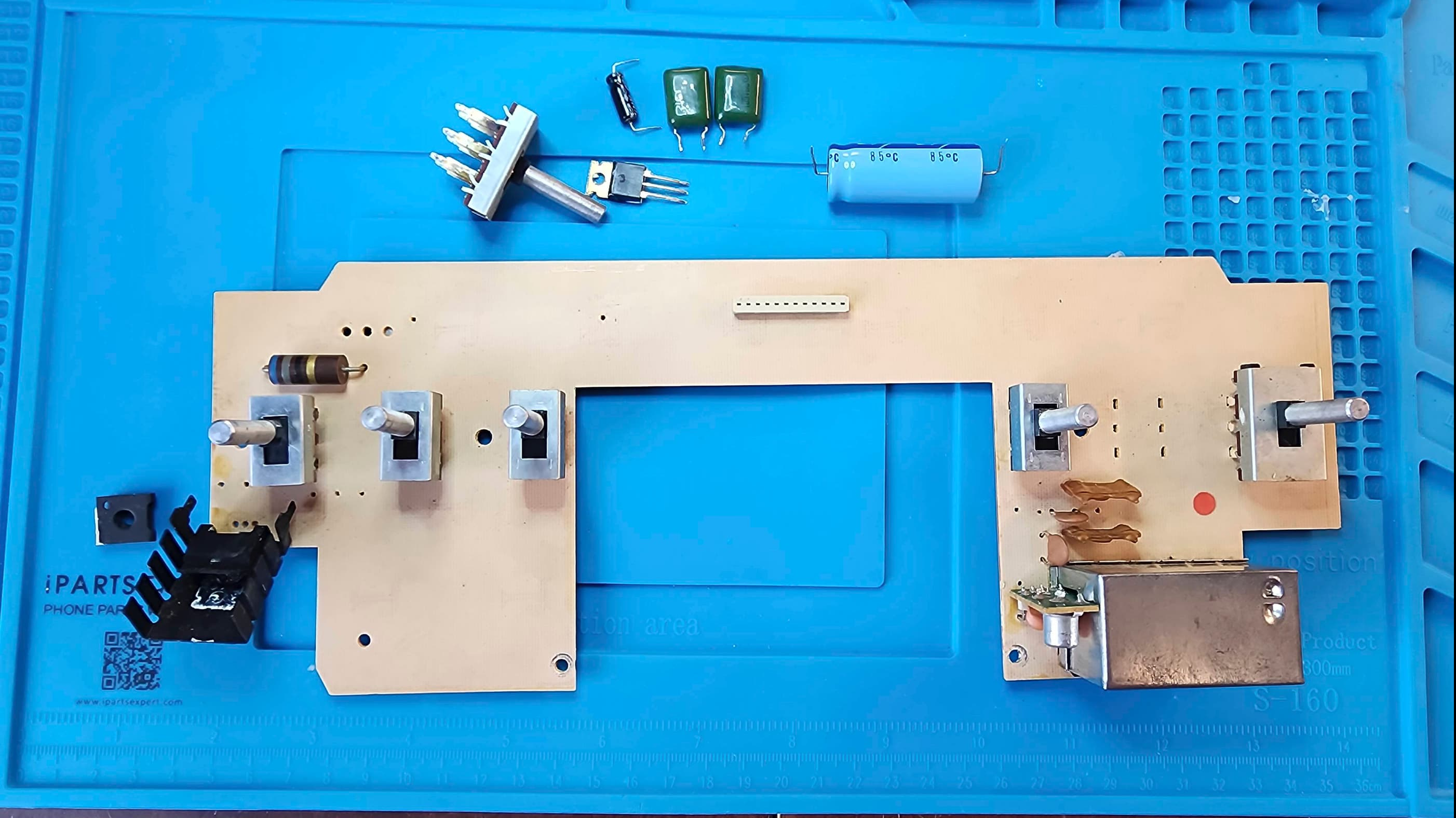
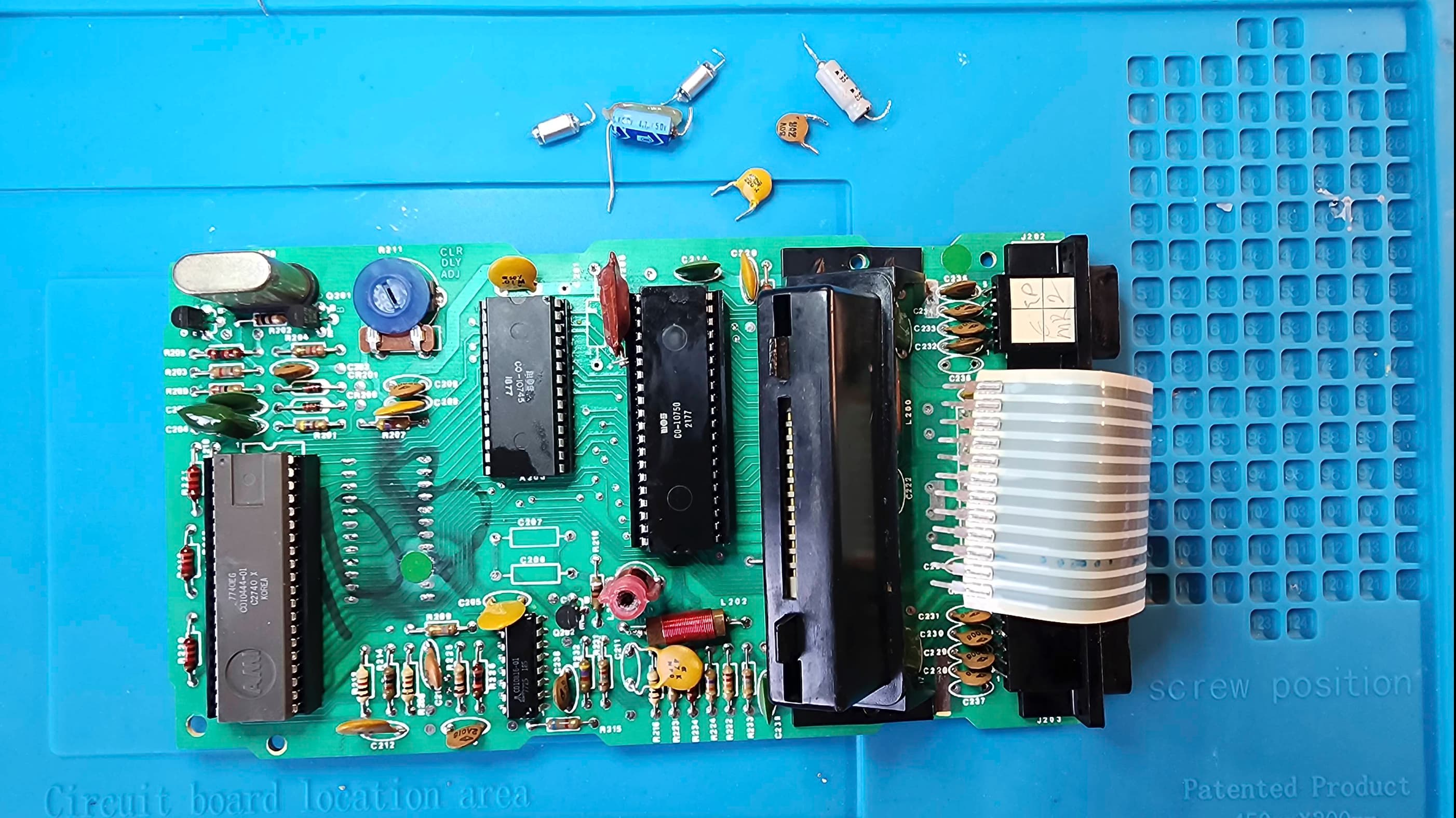
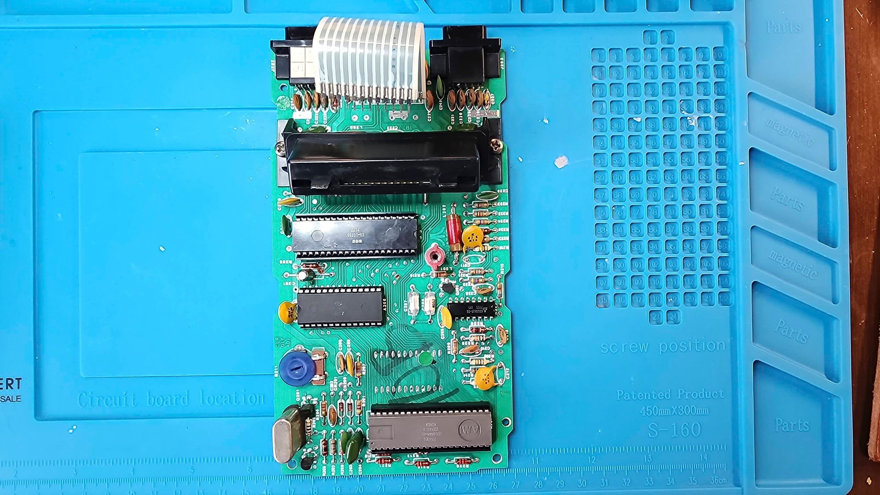
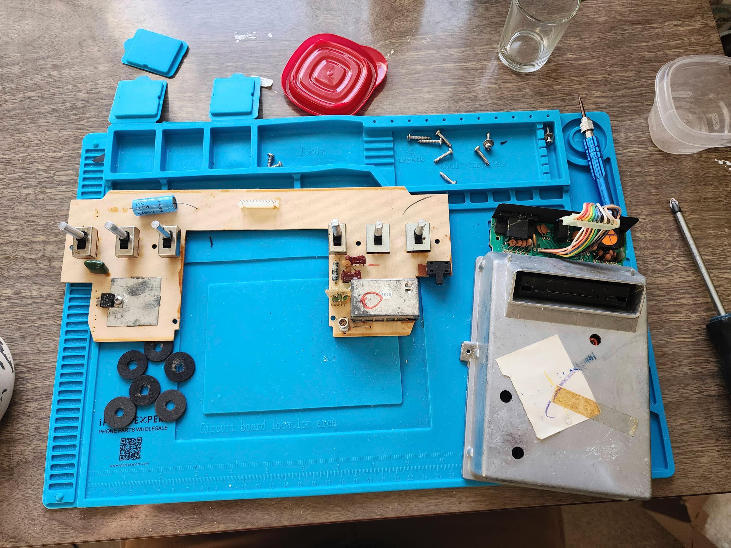
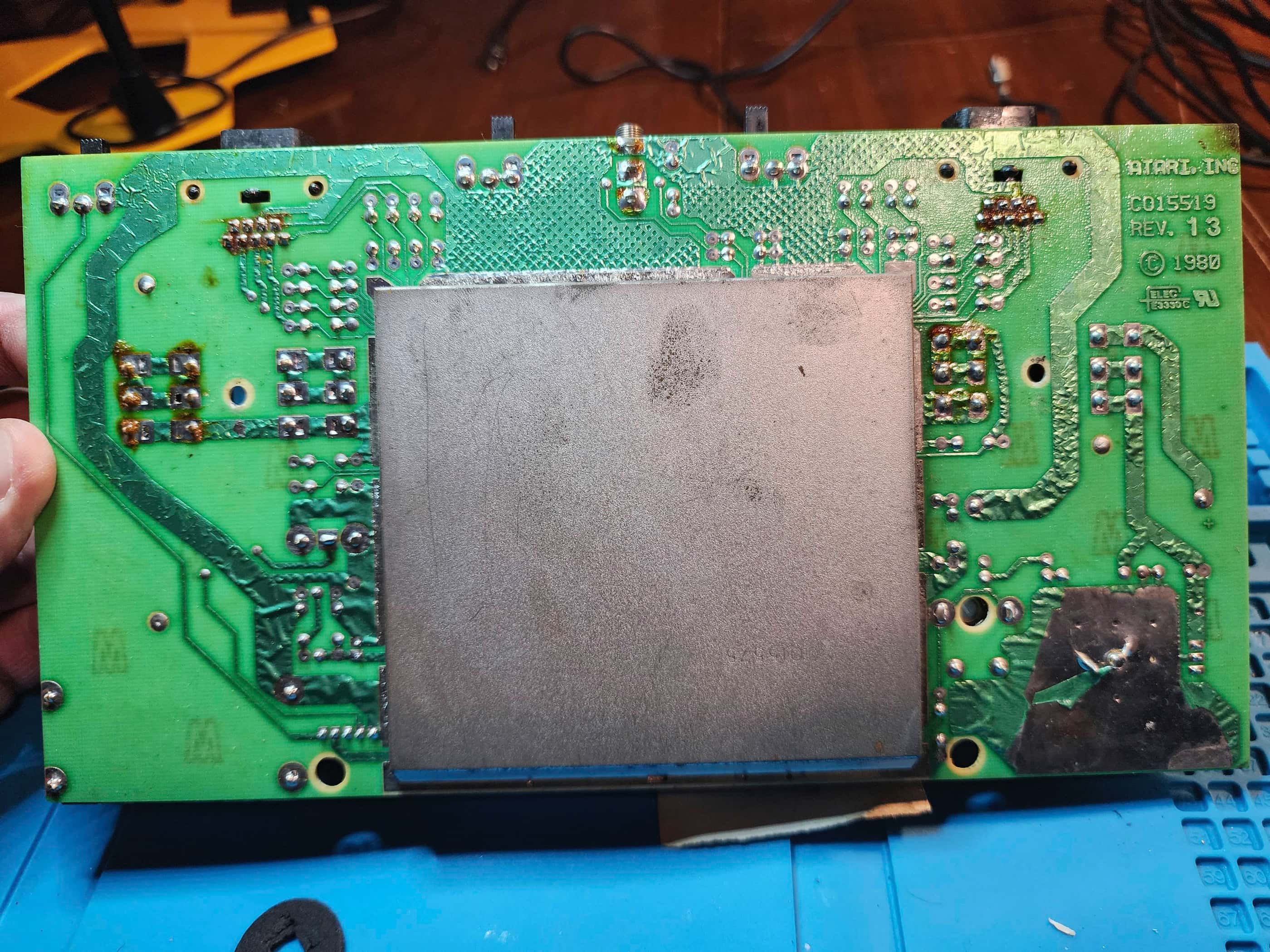
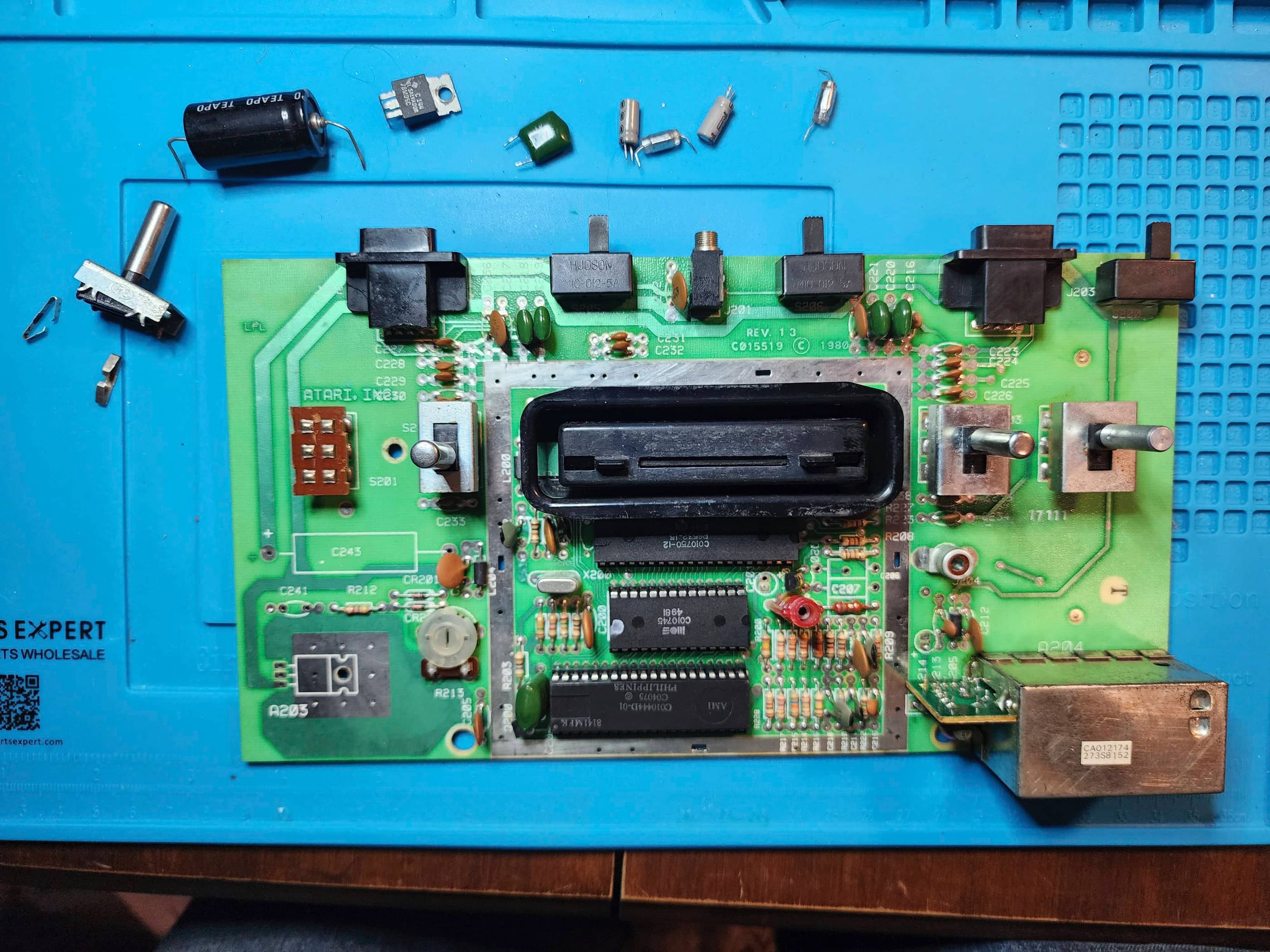
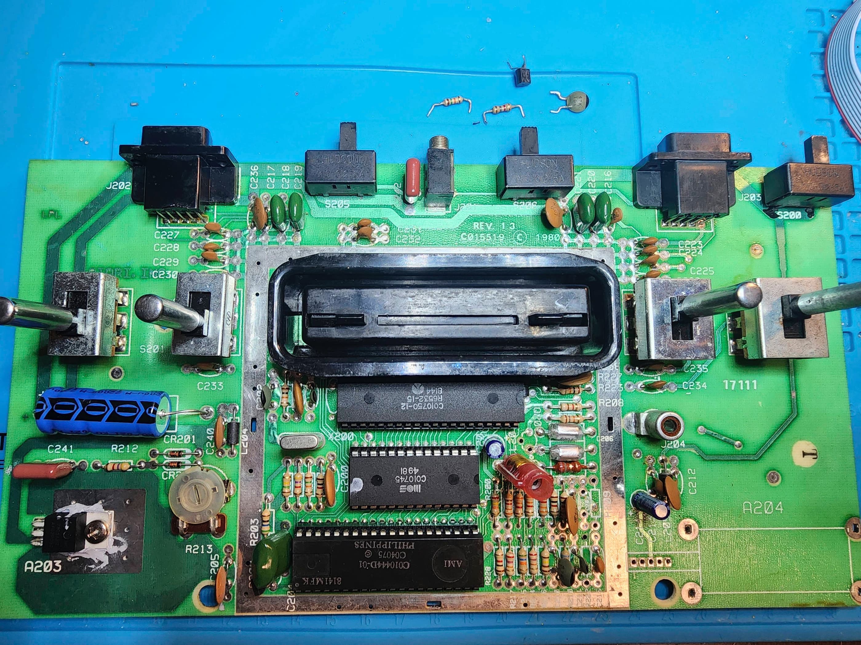
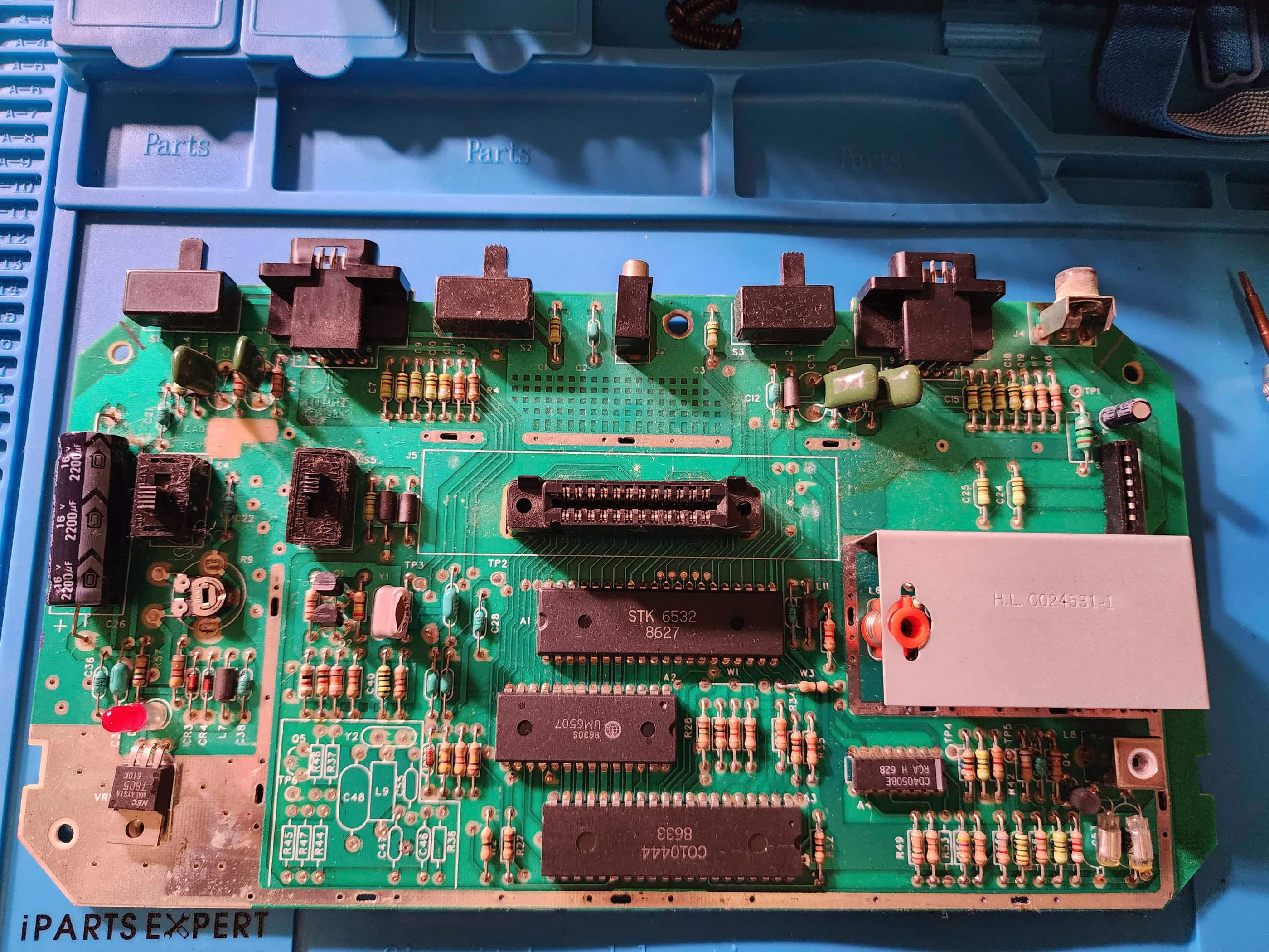
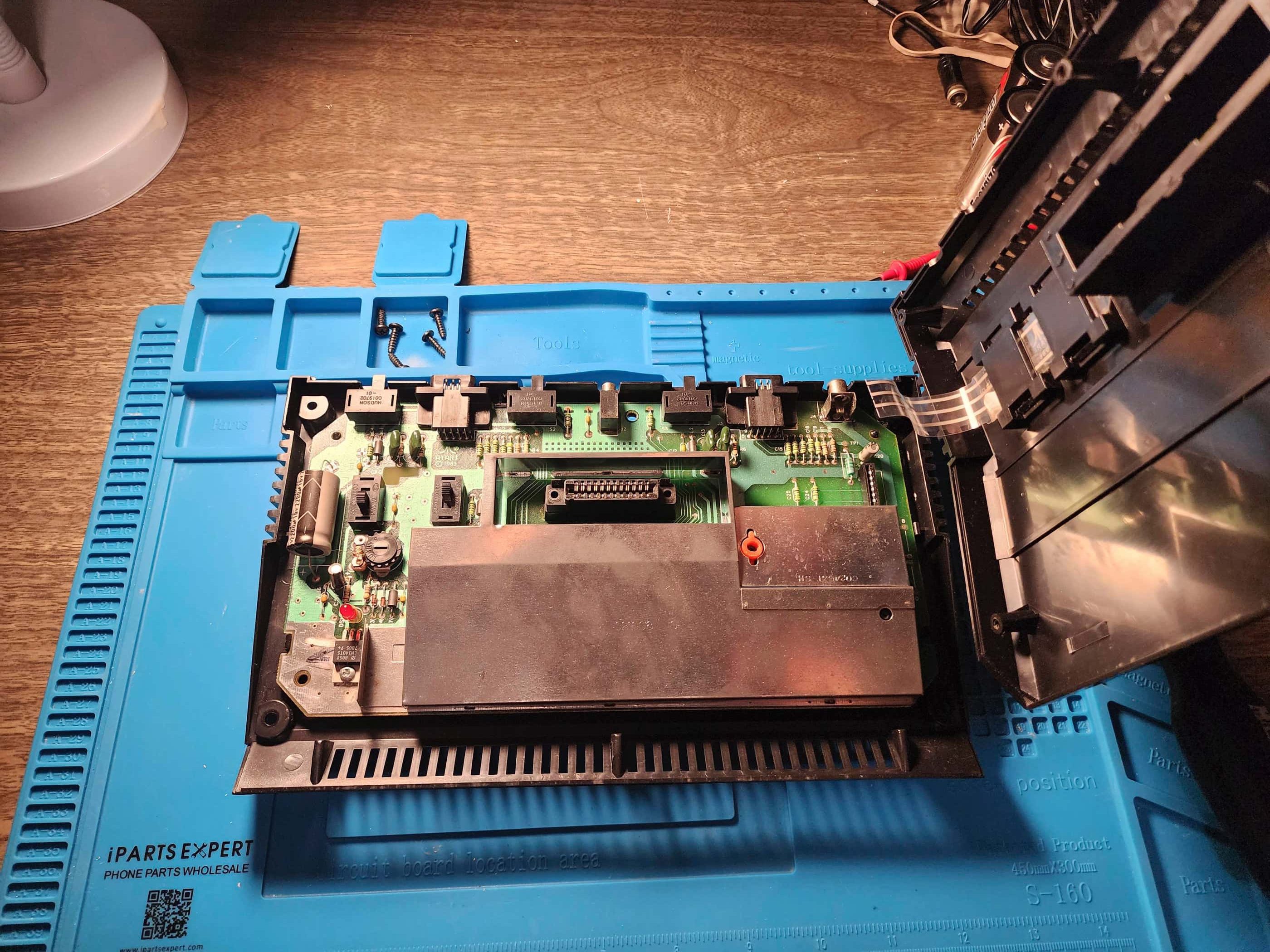
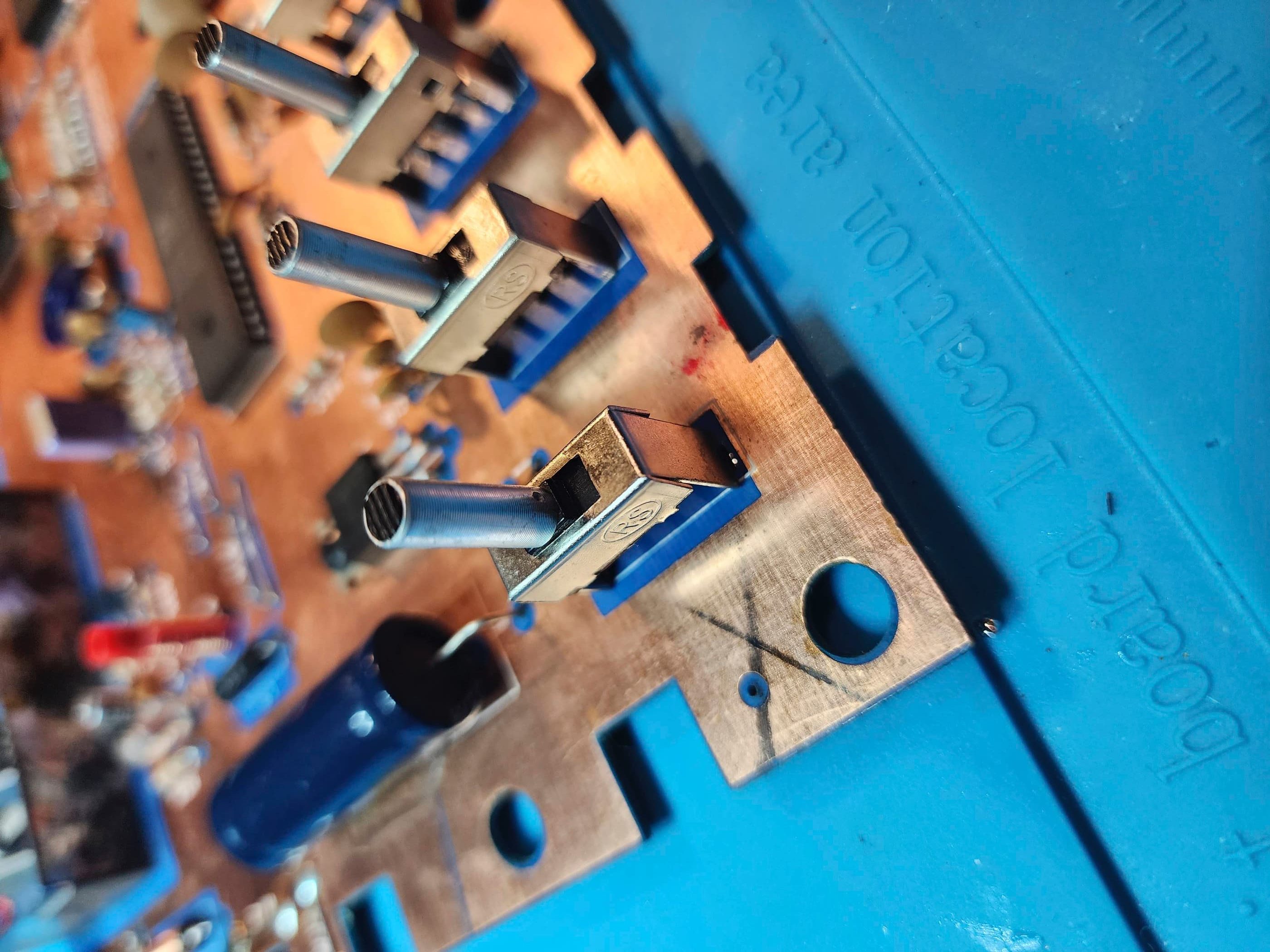
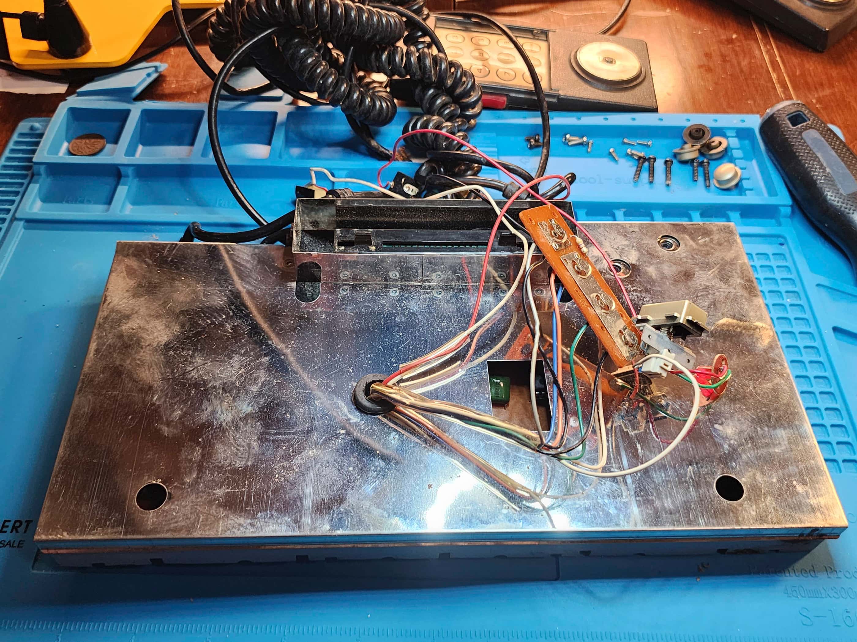
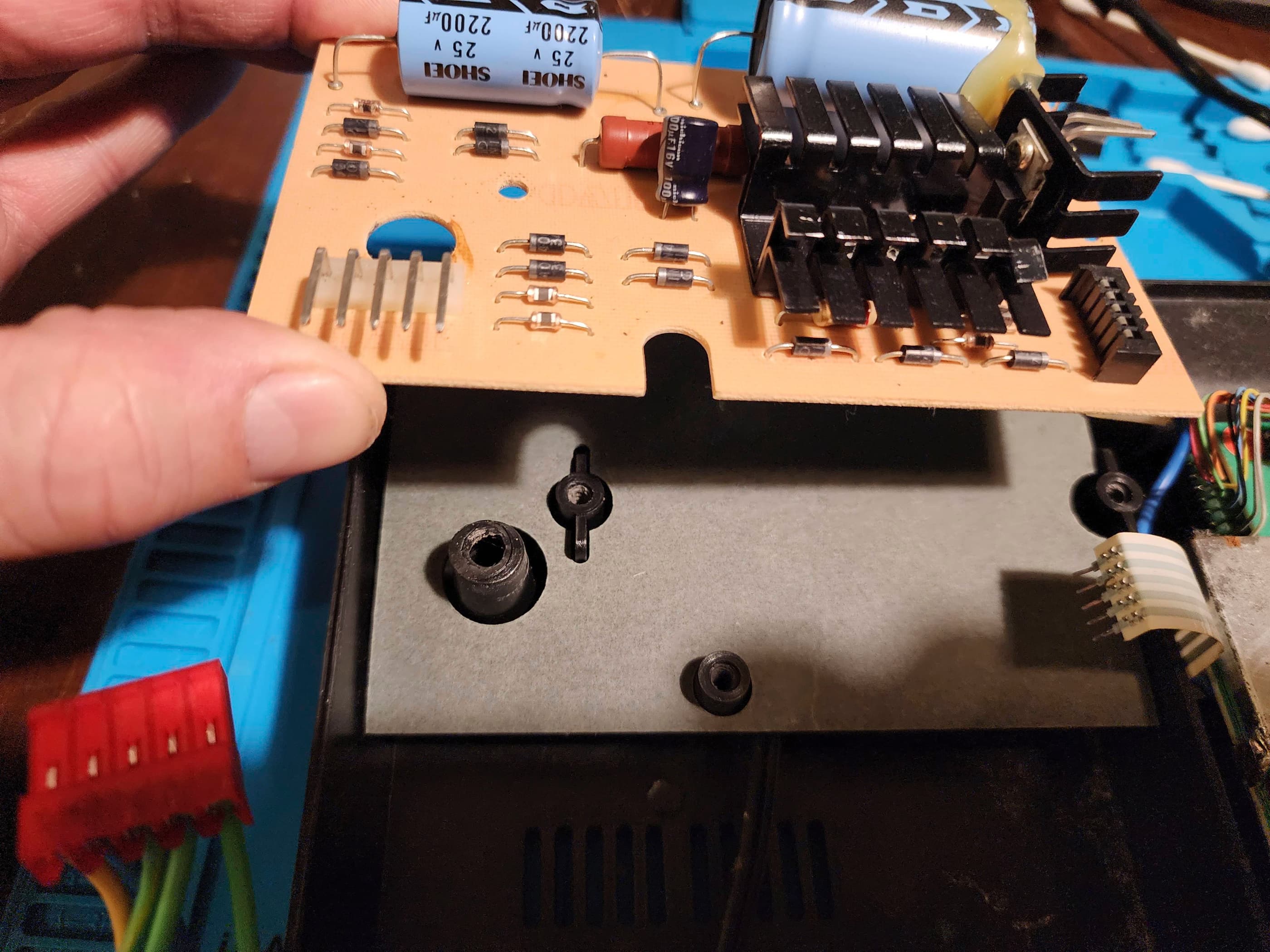
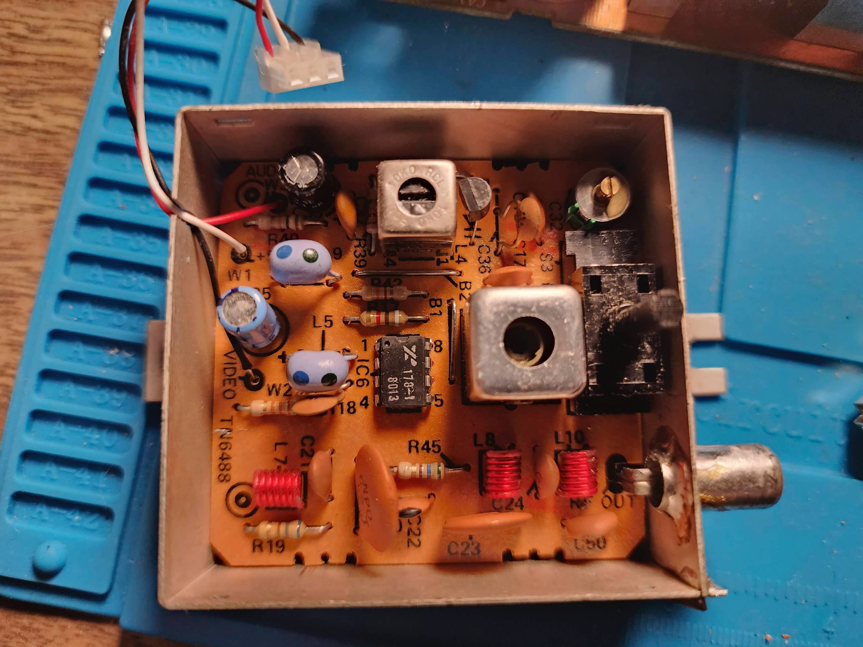
After opening the unit and removing the upper board and then the main board, I noted a few interesting things. First, the upper board did not have a silkscreen labelling the components. It did however, sport the very early Atari slogan, “Innovative Leisure”, which was used by Atari from 1973 until approximately 1978. Second, neither the upper board or the main board had a channel select switch which was common on early model heavies.
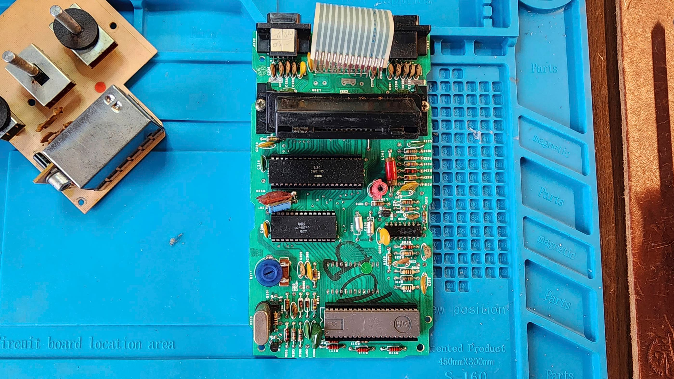
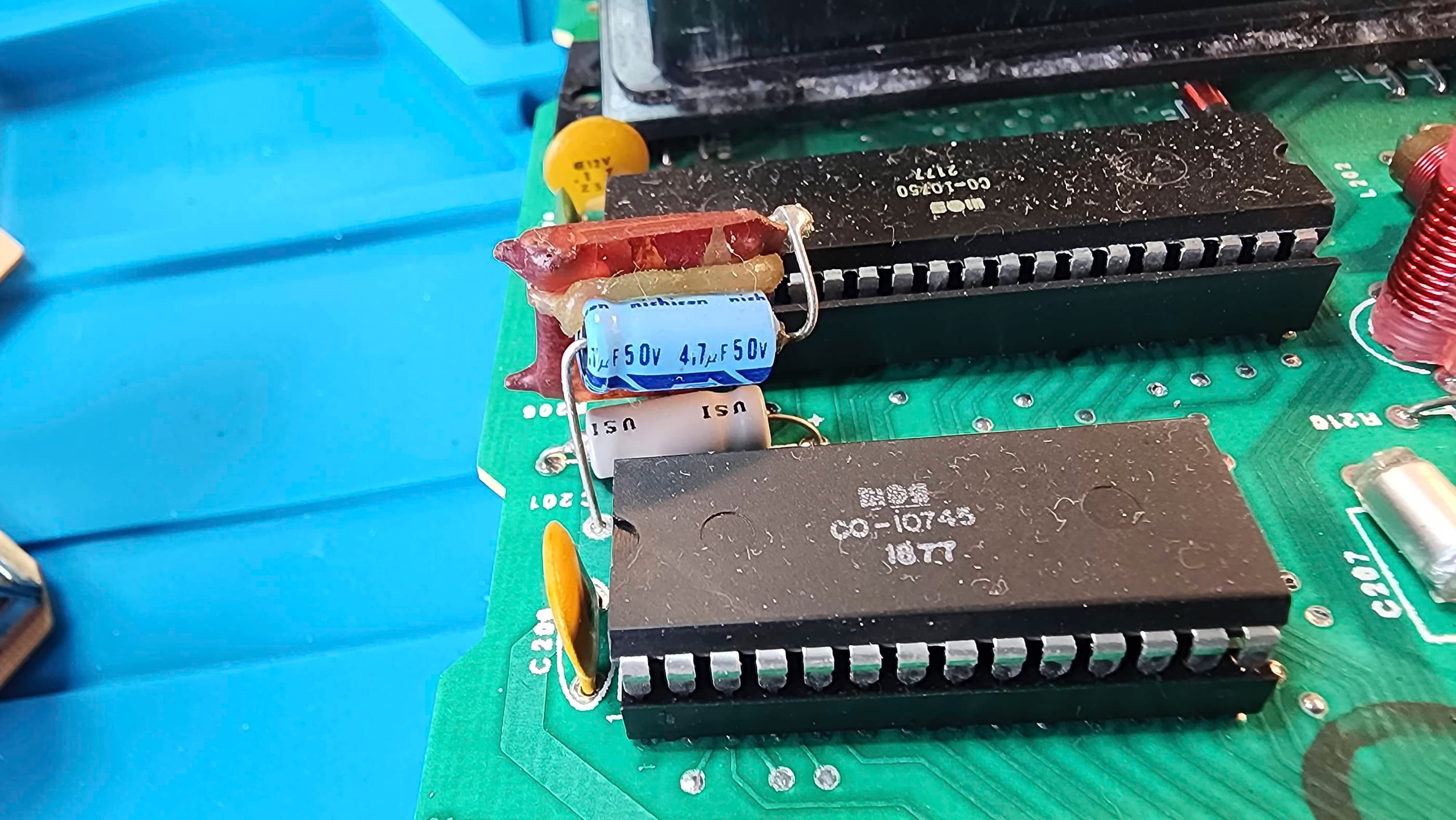
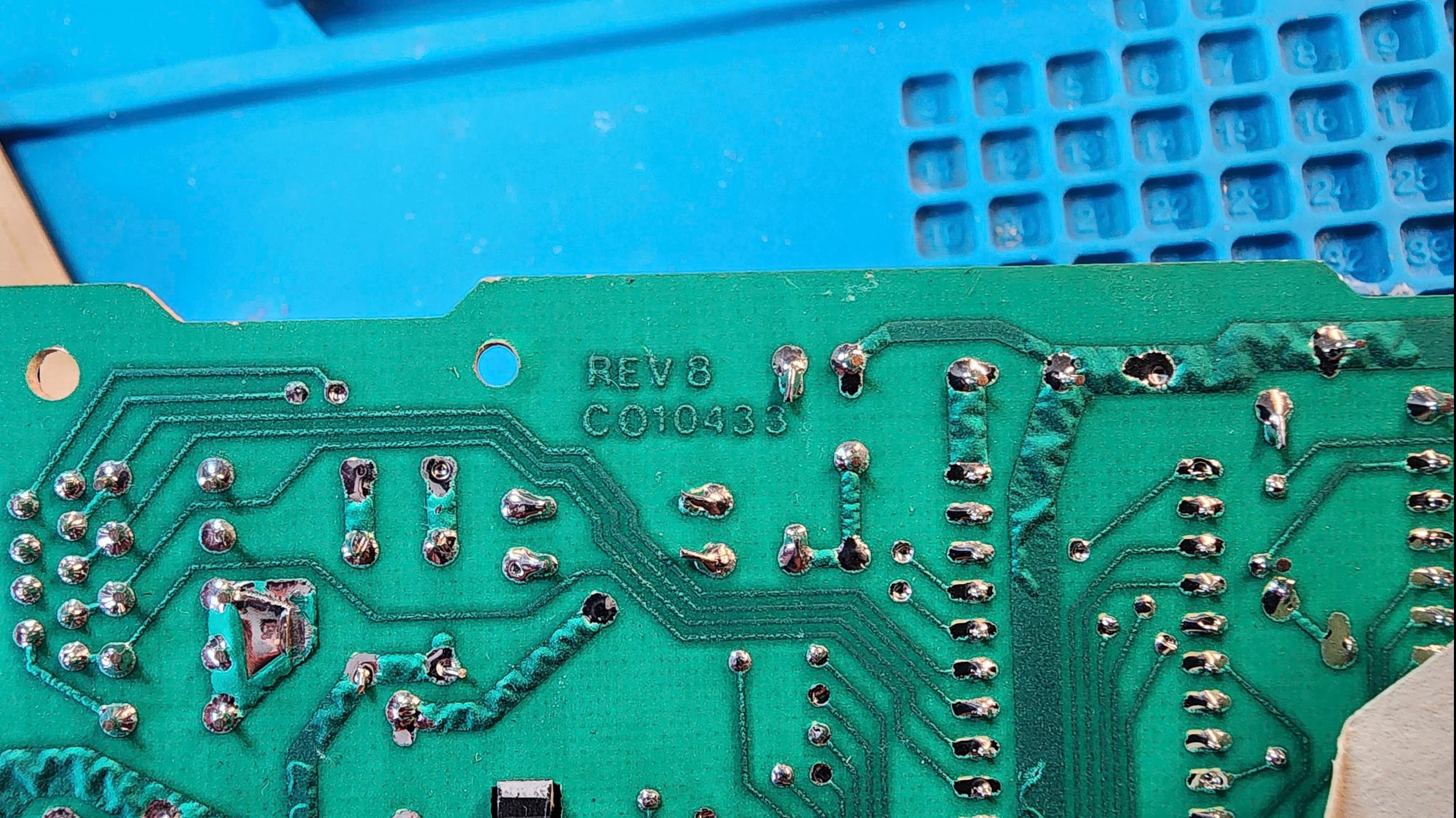
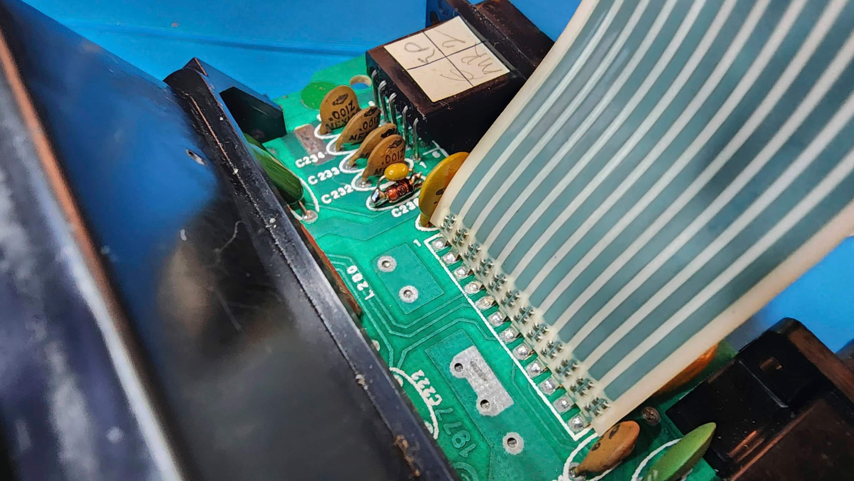
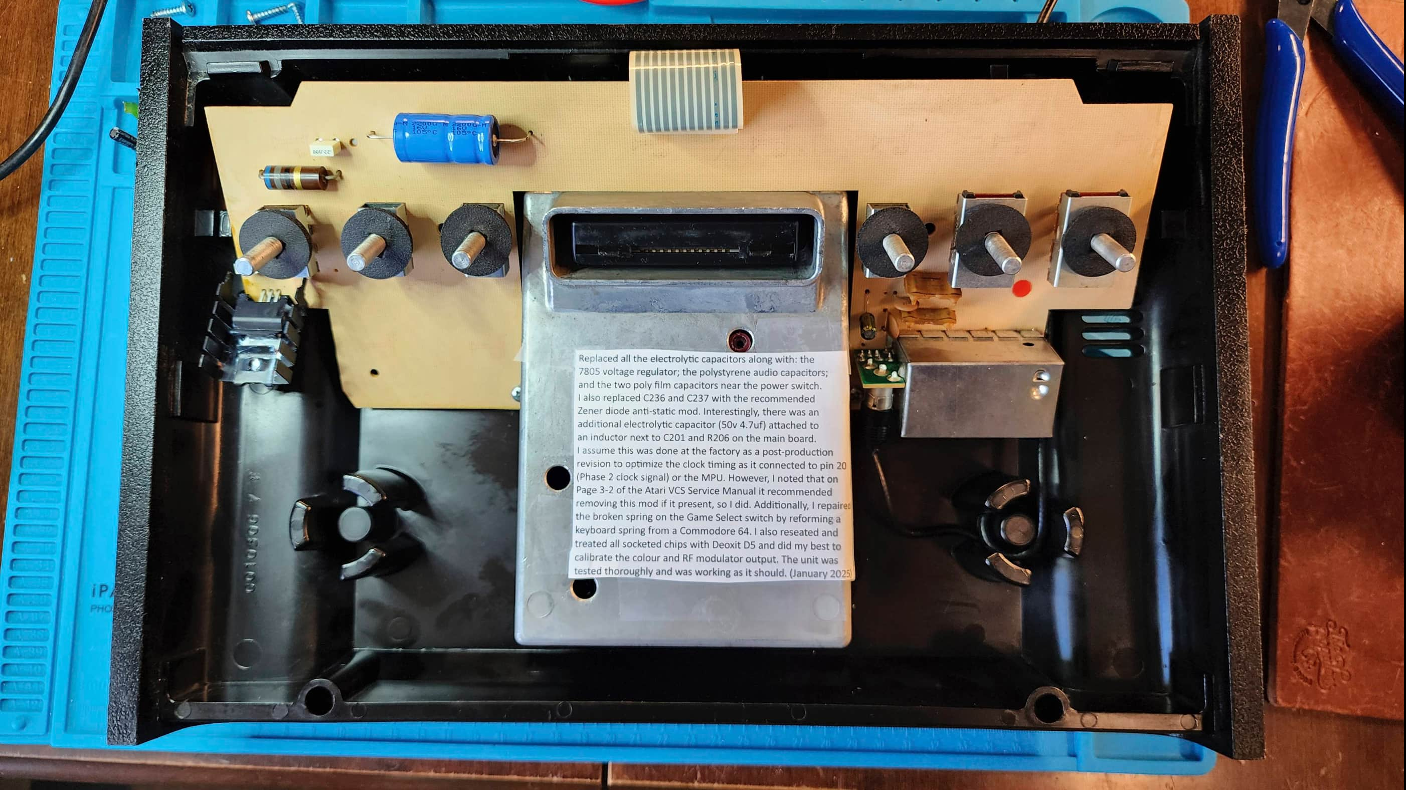
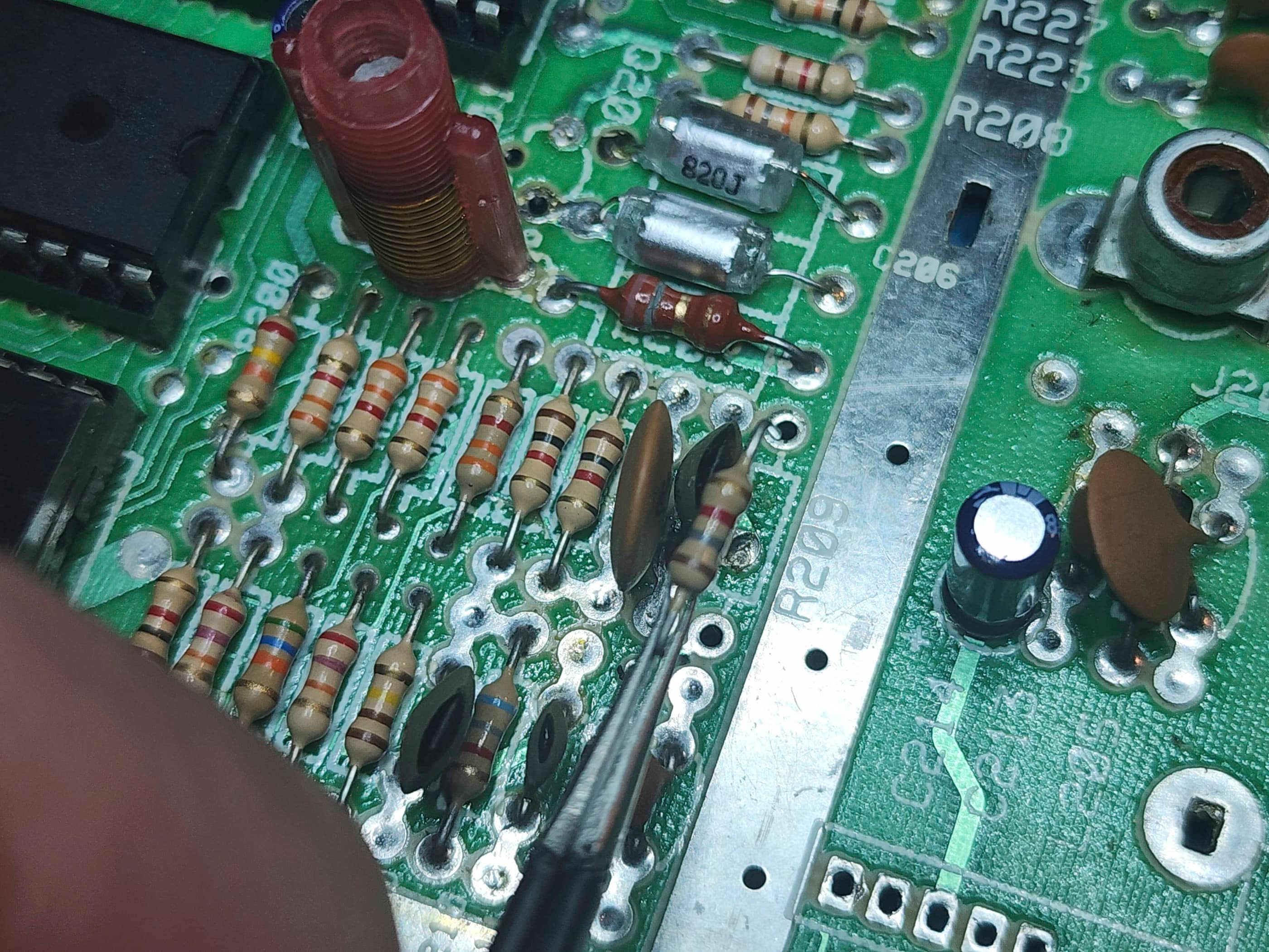
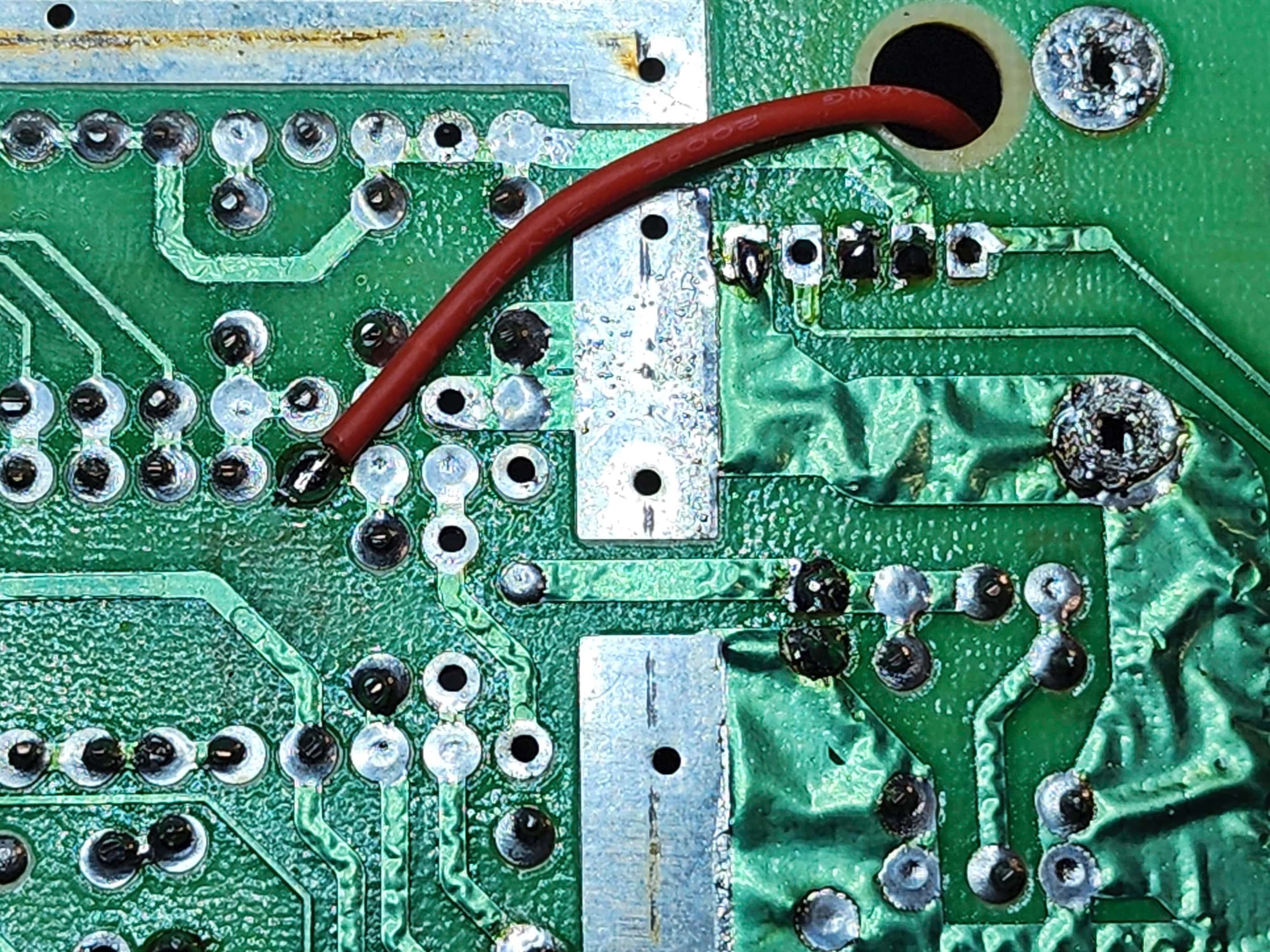
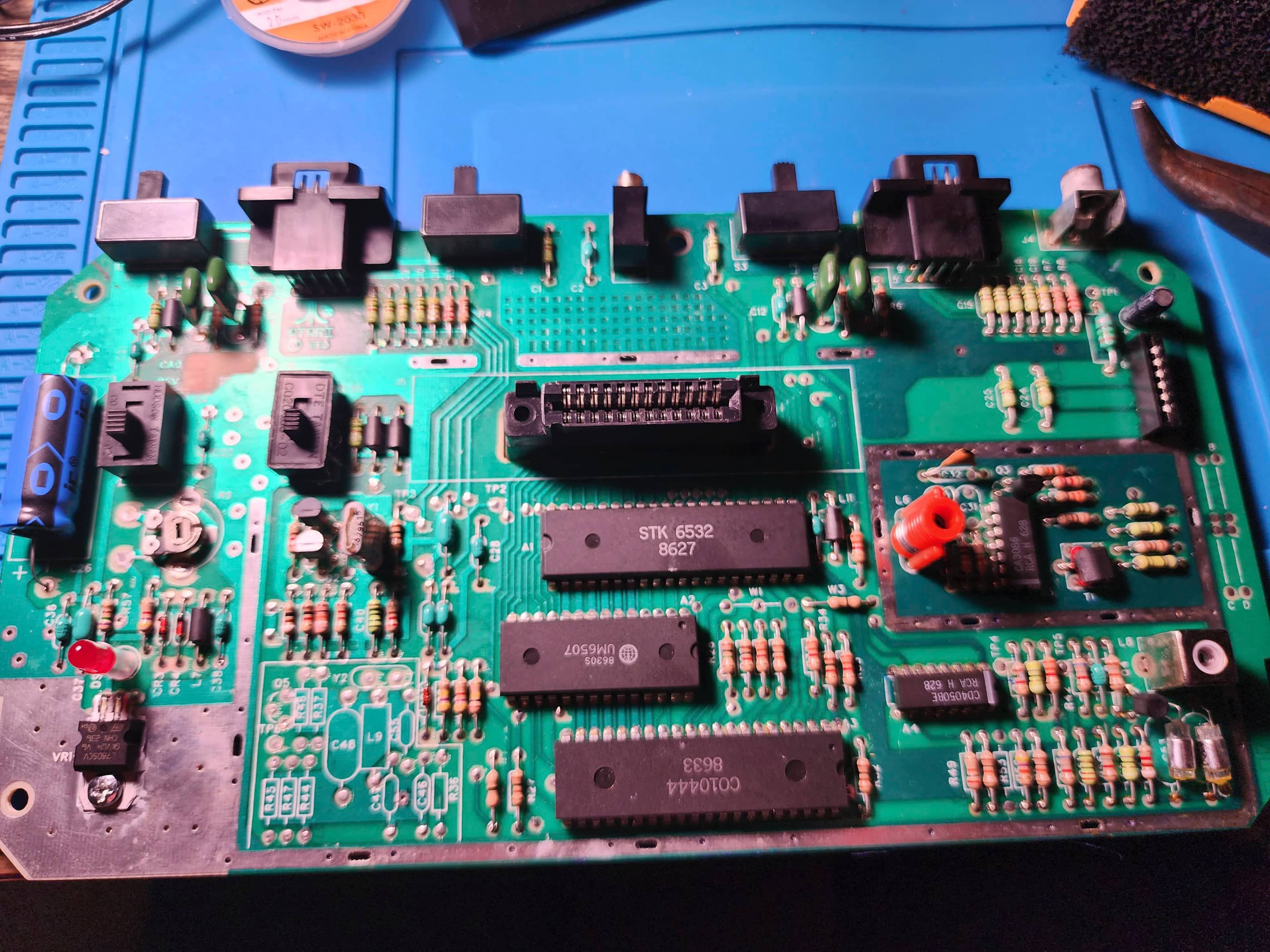
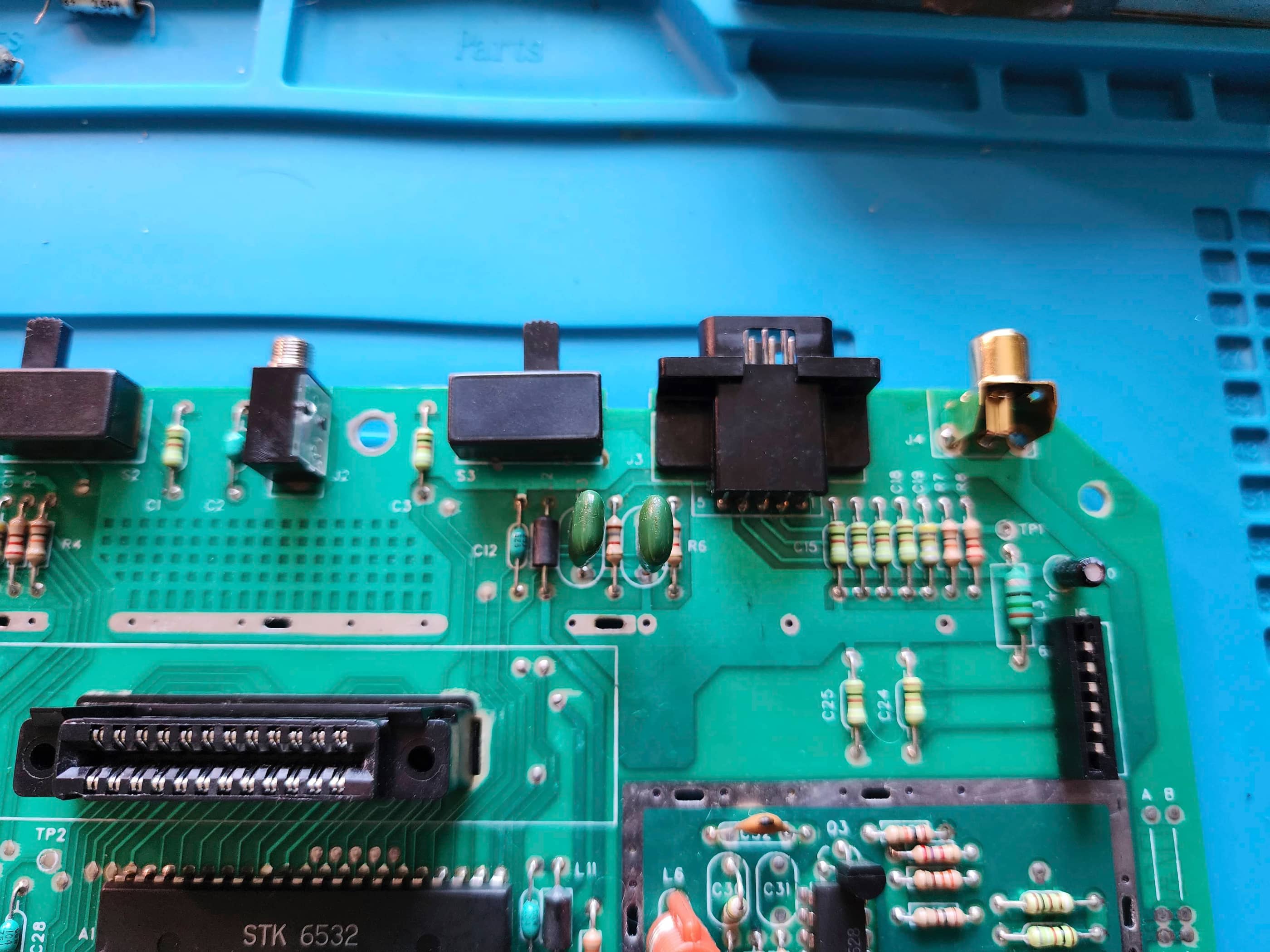
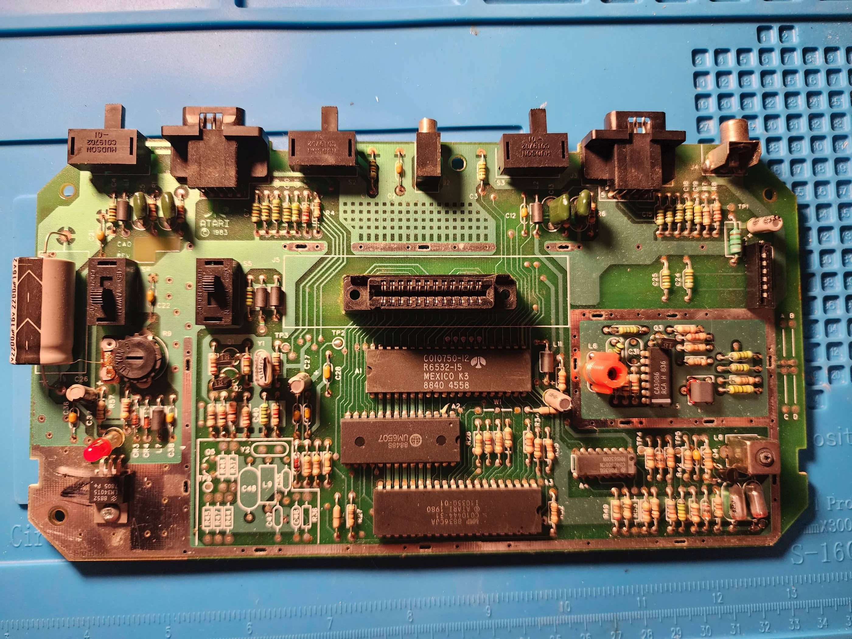
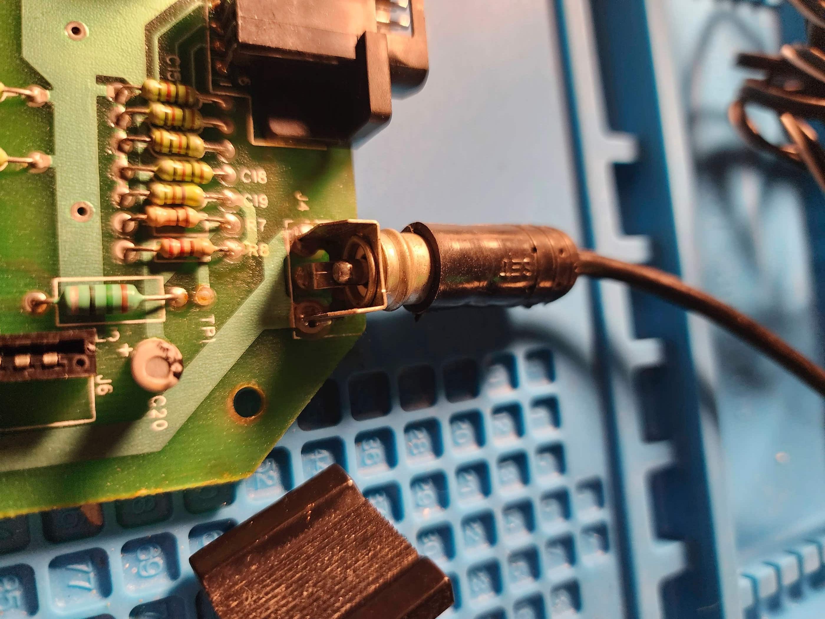
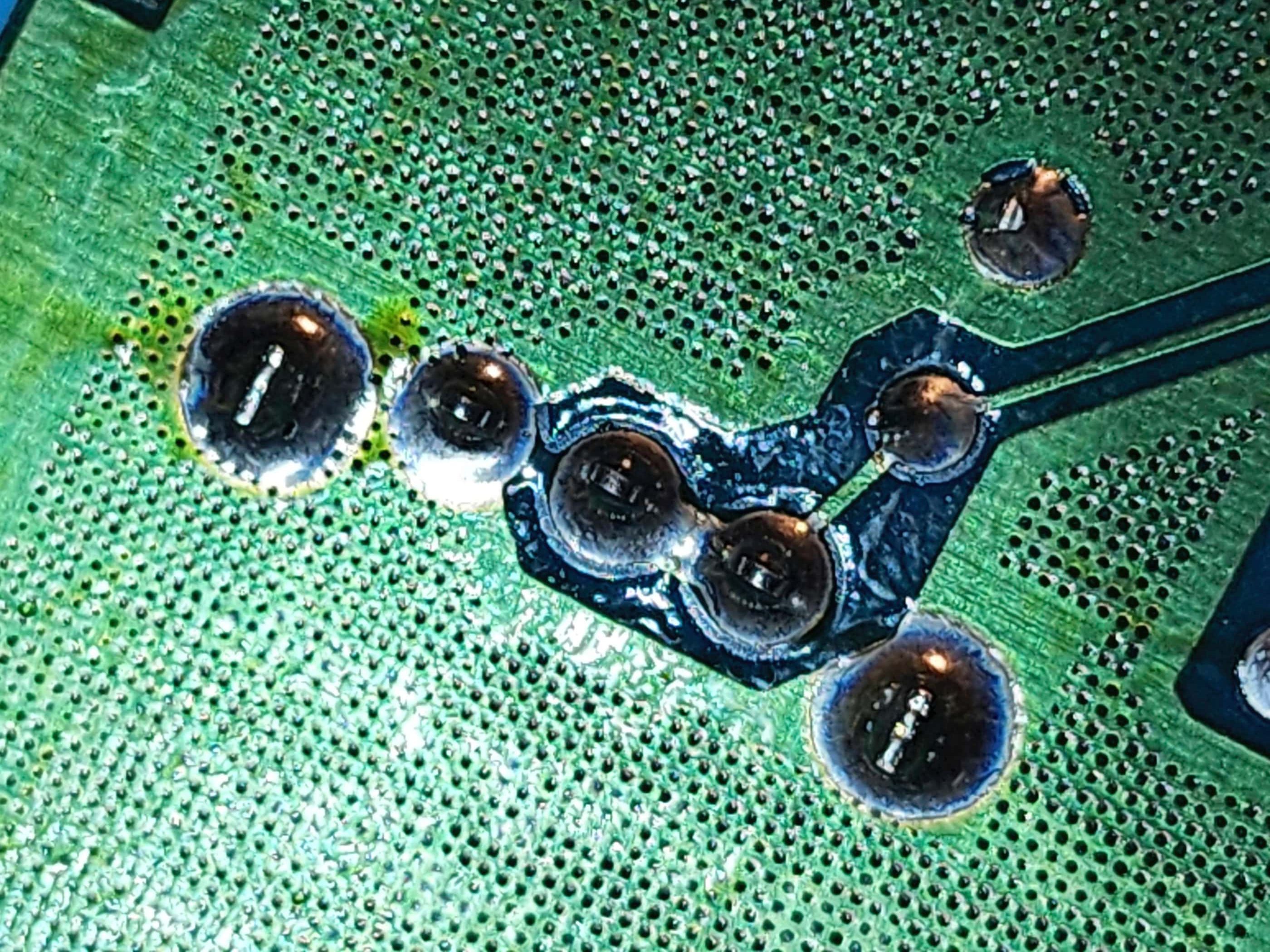
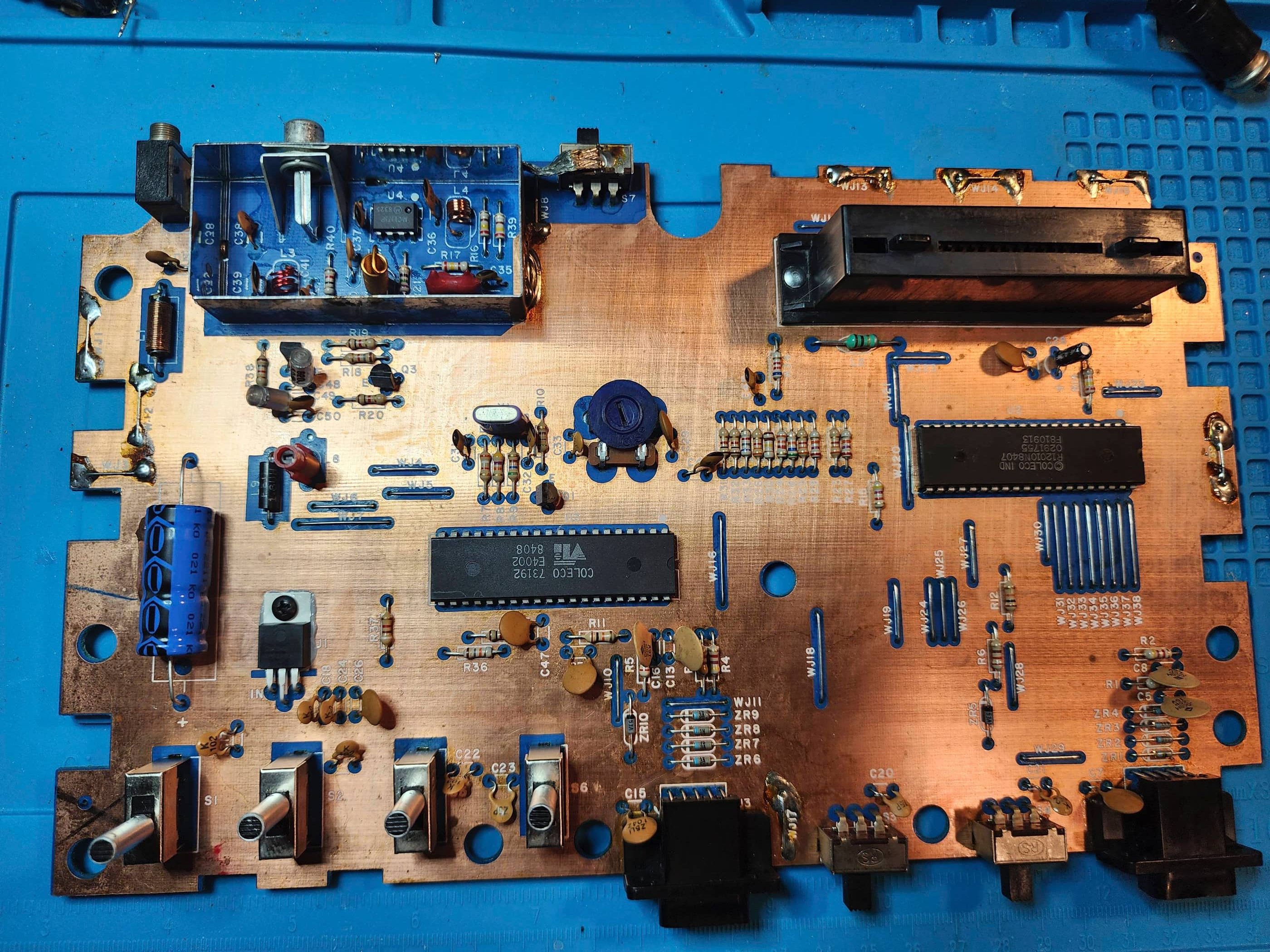
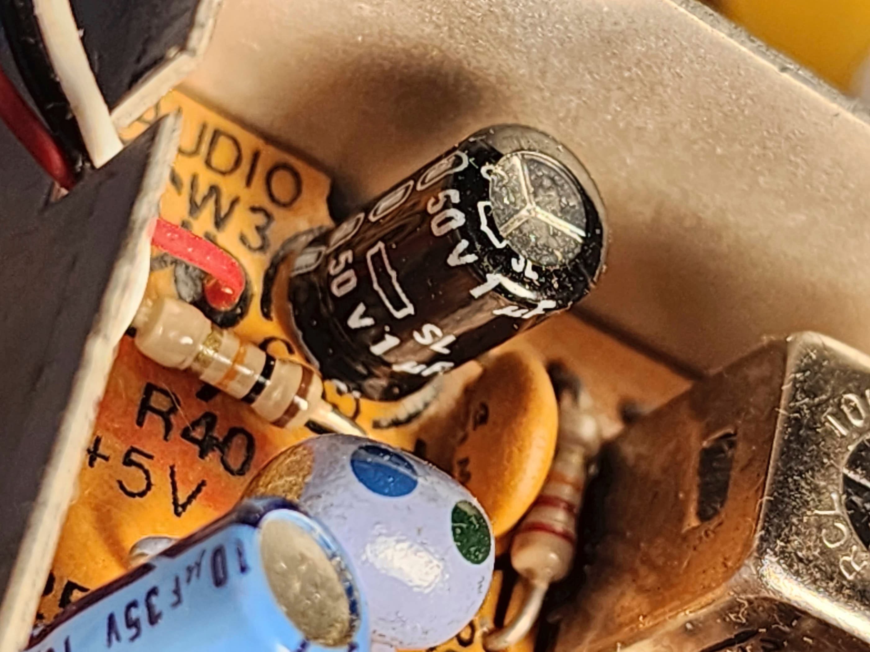
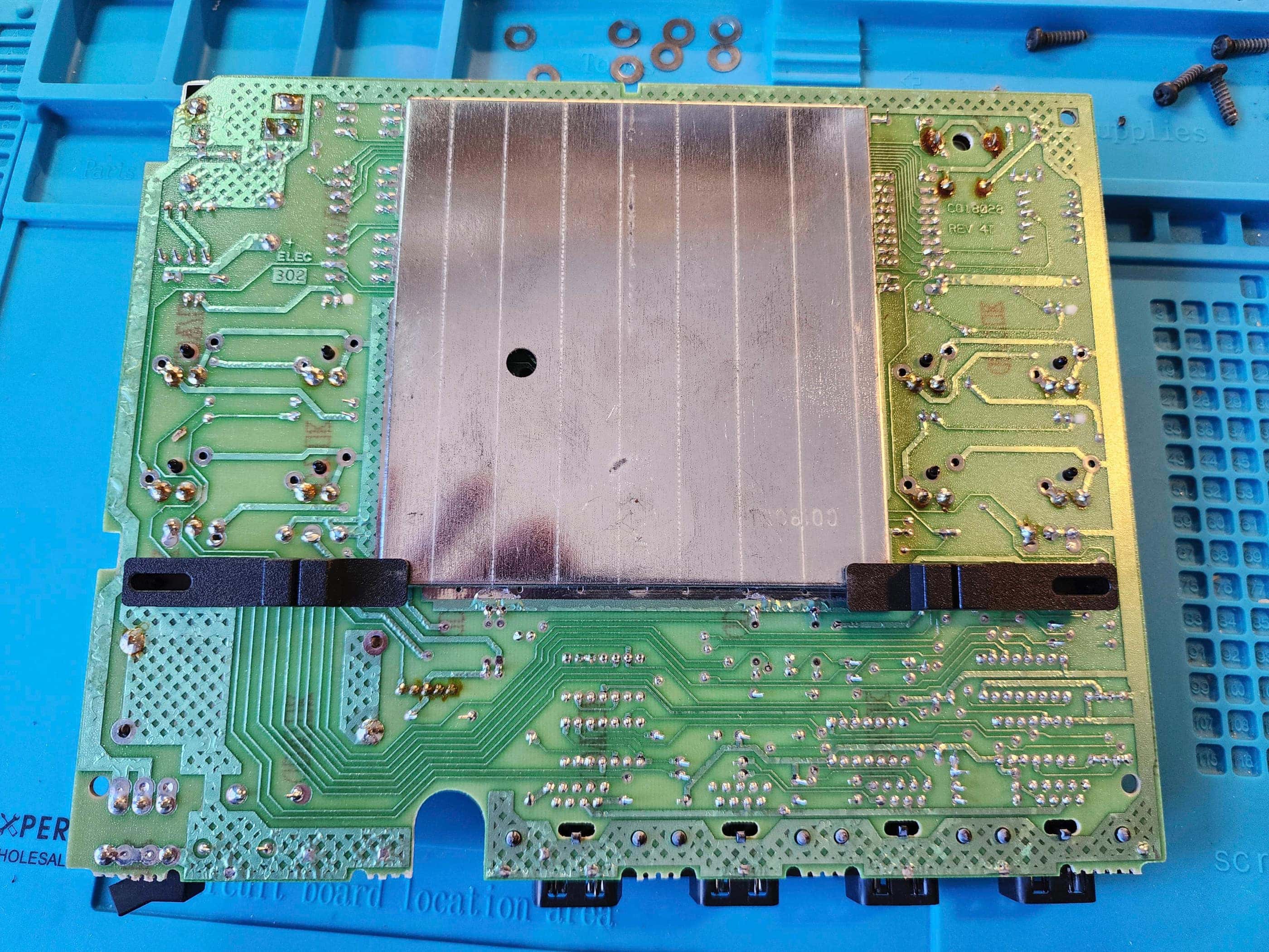
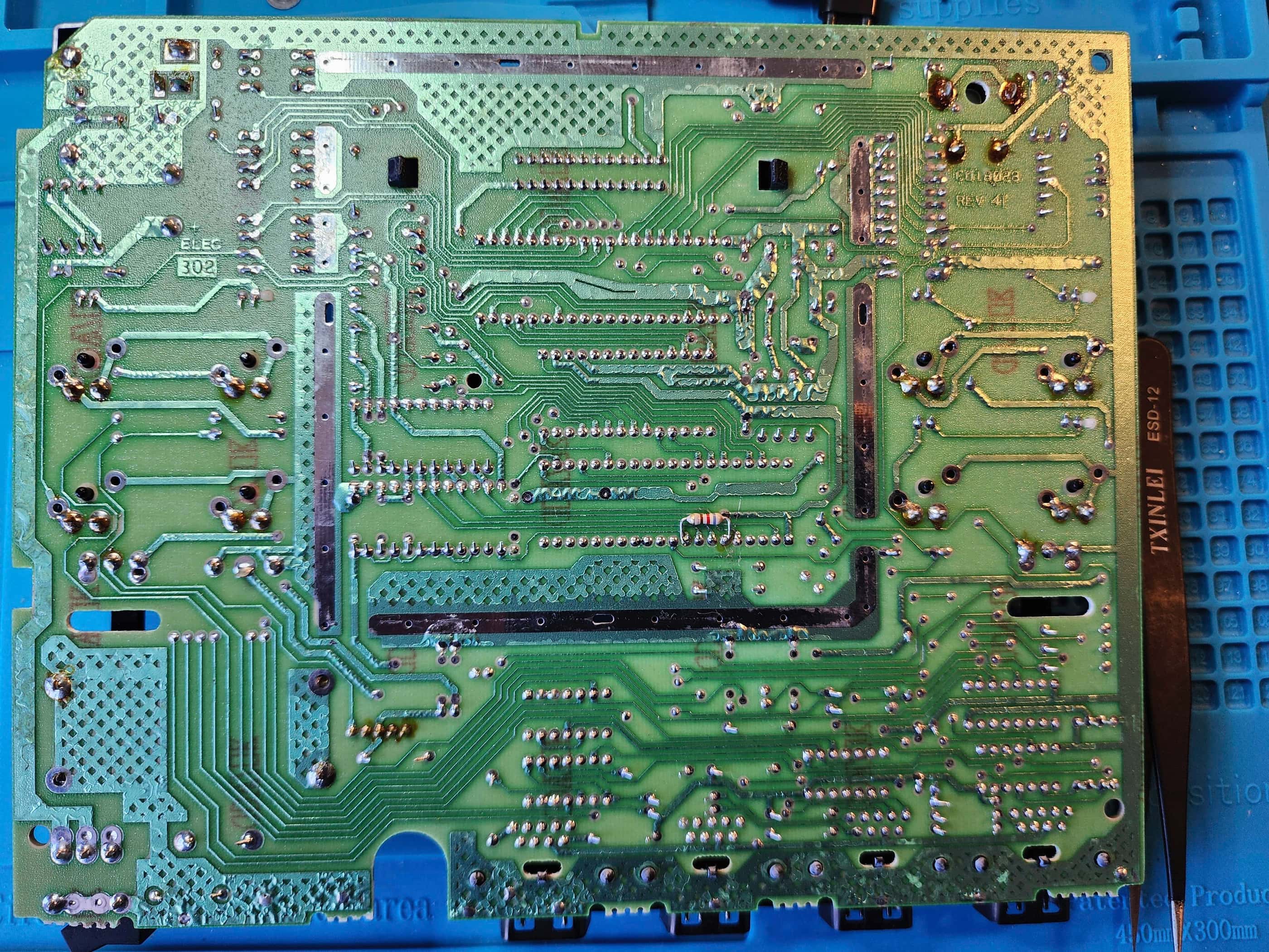
Finally, the main board was a CO10433 REV 8; however, it had a very interesting mod that I have not been able find on any schematic. Immediately above C201 and R206 there was an inductor with a 50v 4.7uf electrolytic capacitor attached to it. The positive arm of the capacitor went through the board and connected with the trace from pin 28 of the MPU (A200) which is the Phase 2 clock signal. The negative arm of the capacitor connected with one arm of the inductor, while the second arm of the inductor connected with a trace that led to a via under the 6532 (A202). From there, the via led to Pin 39 of the 6532 (Phase 2 clock signal) and then to Pin 20 (Phase 2 clock signal) of the TIA (A201). The weird part was the traces and the through holes looked like they were made for these components, but they weren’t labelled on the silkscreen.
Furthermore, besides not being able to find this mod on a schematic, I couldn’t find a photo or online discussion of it – until I read the Atari VCS Service Manual. On page 3-2, bullet point #7 under the sub-heading “2600 Model Modifications” stated, “Check for an inductor and capacitor over C20 l and R206. Cut the inductor and cap out, being careful not to cut the C20 l or R206 leads.” So, in following the recommendation of the manual, I de-soldered and removed the inductor and the capacitor.
I’m fairly certain that this was a factory mod that was designed to stabilize and/or tweak the timing signal coming from the MPU. That I haven’t found another example of it is odd, but that it was obviously designed into the board (albeit with no silkscreen markings) is very interesting. If I’m able to find another “Heavy Sixer” one day, I’ll be curious to compare the boards.
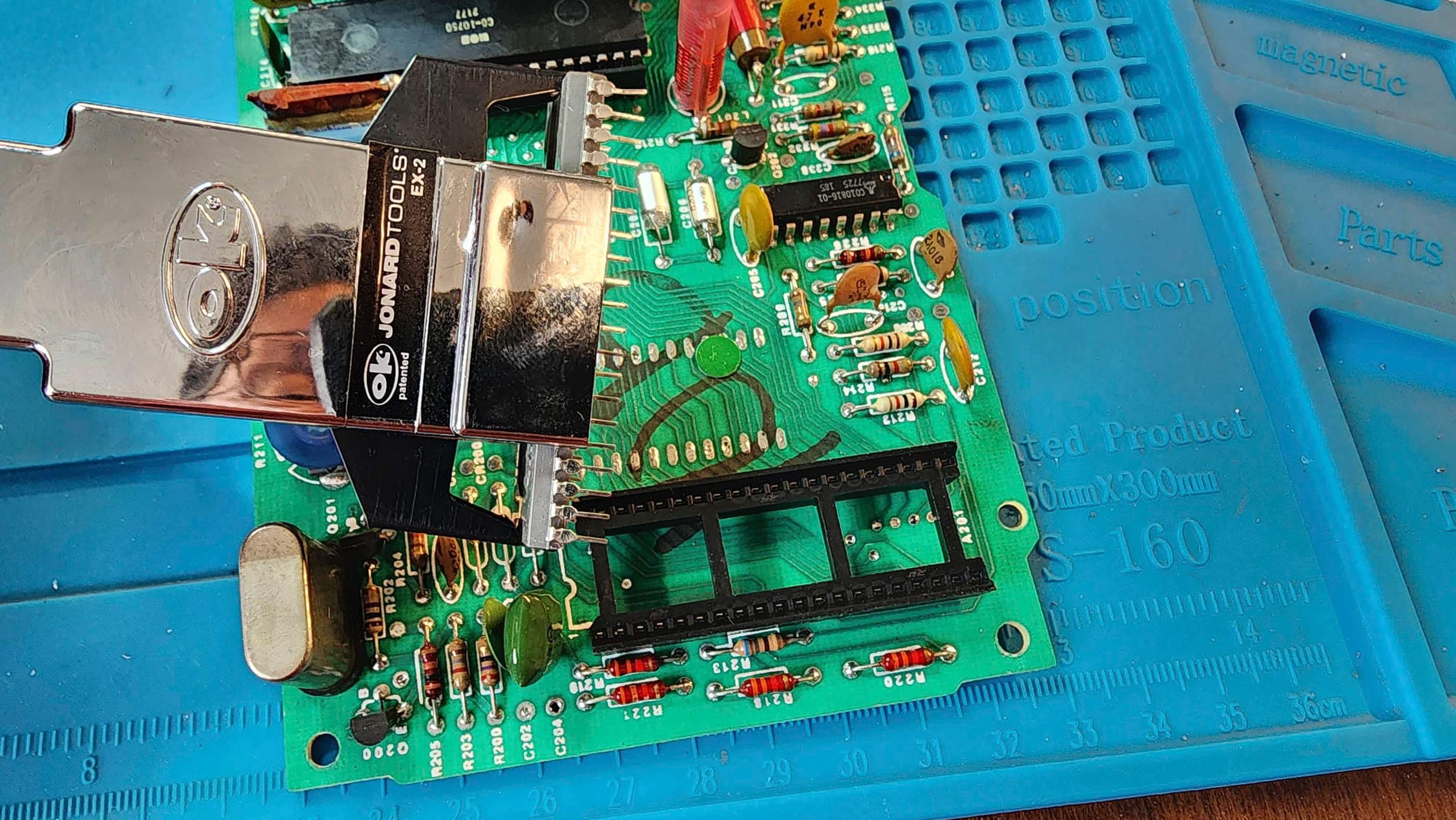
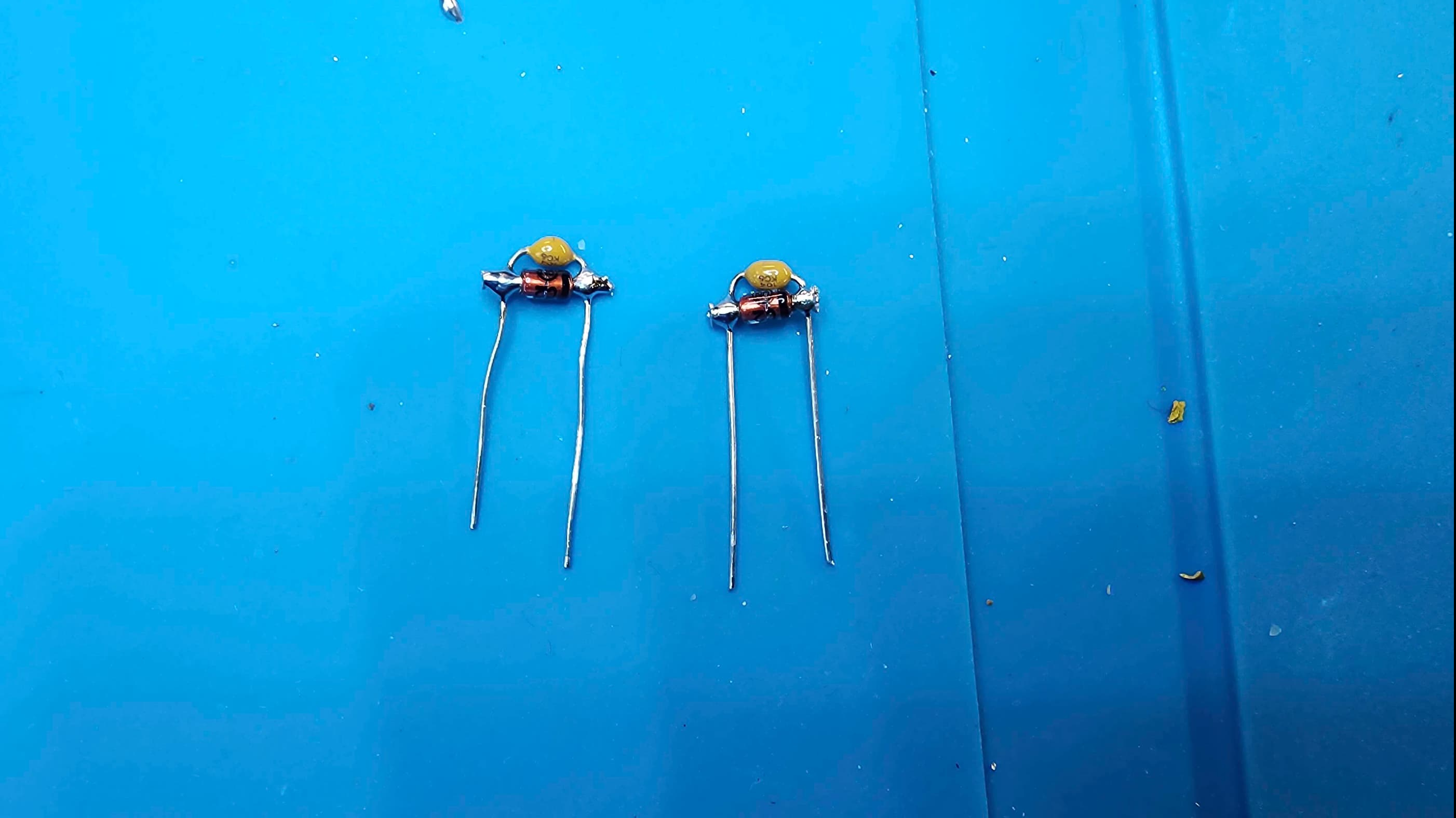
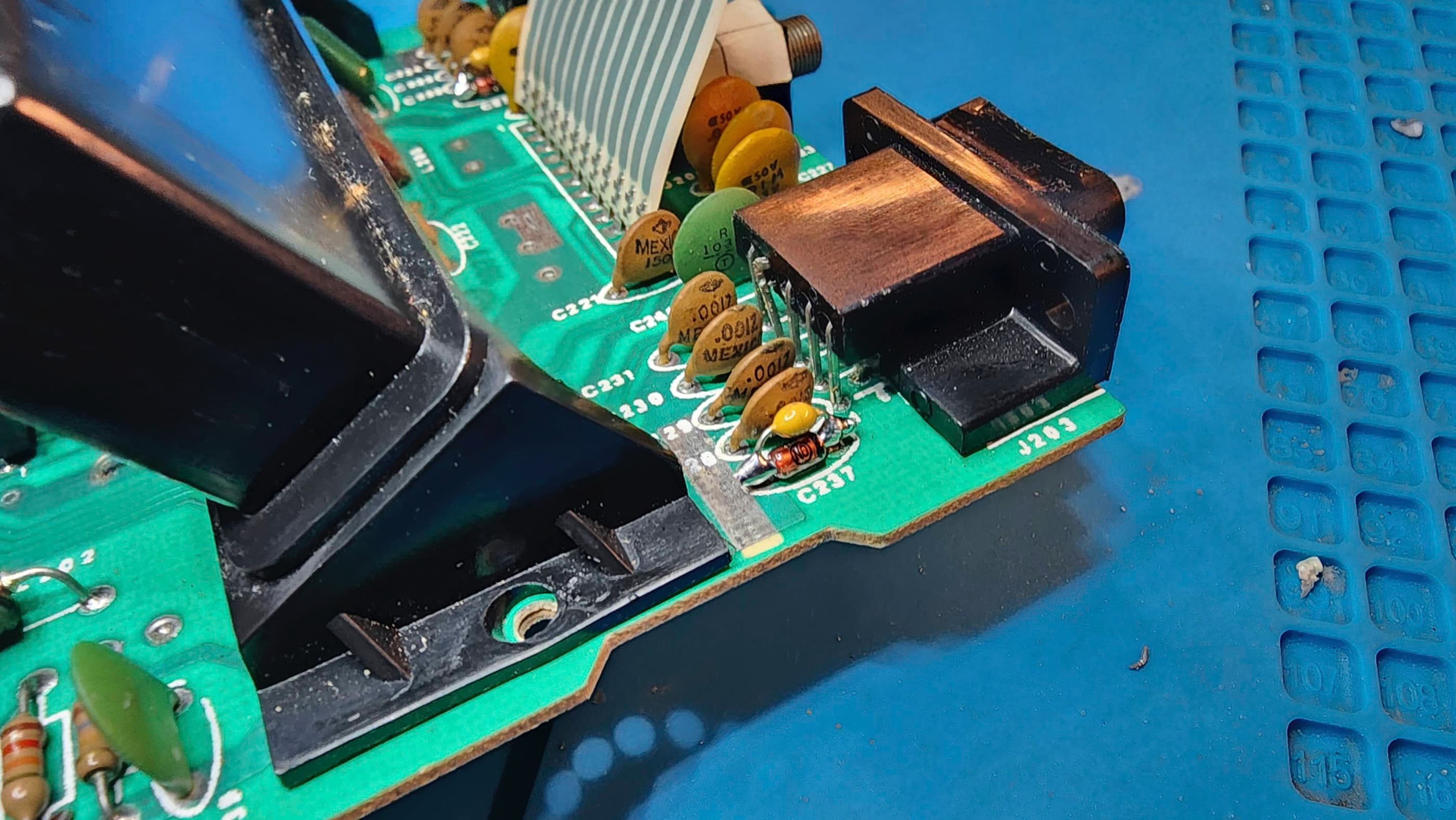
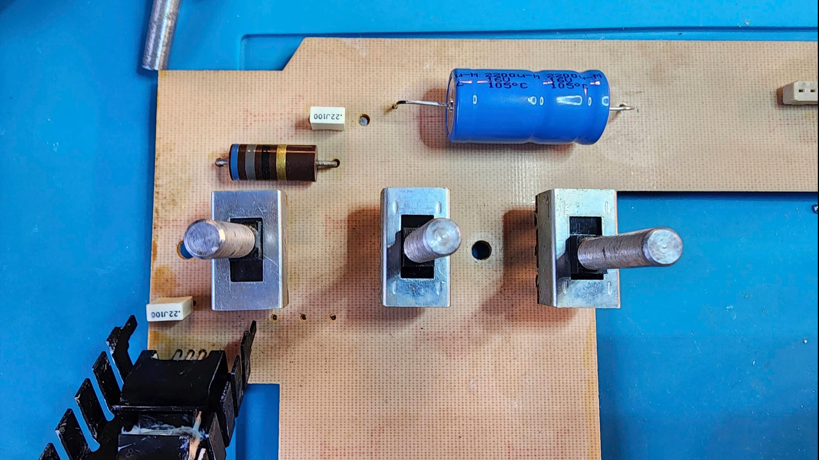
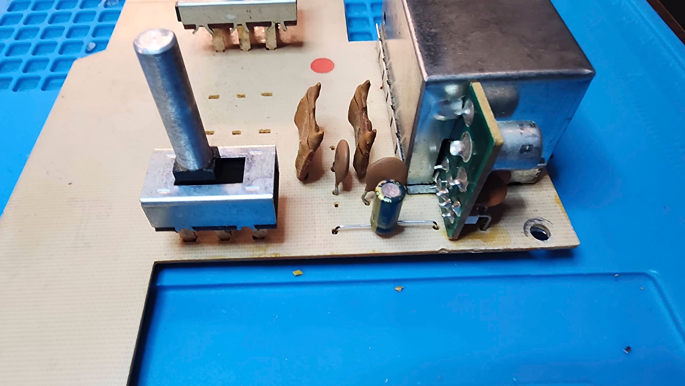
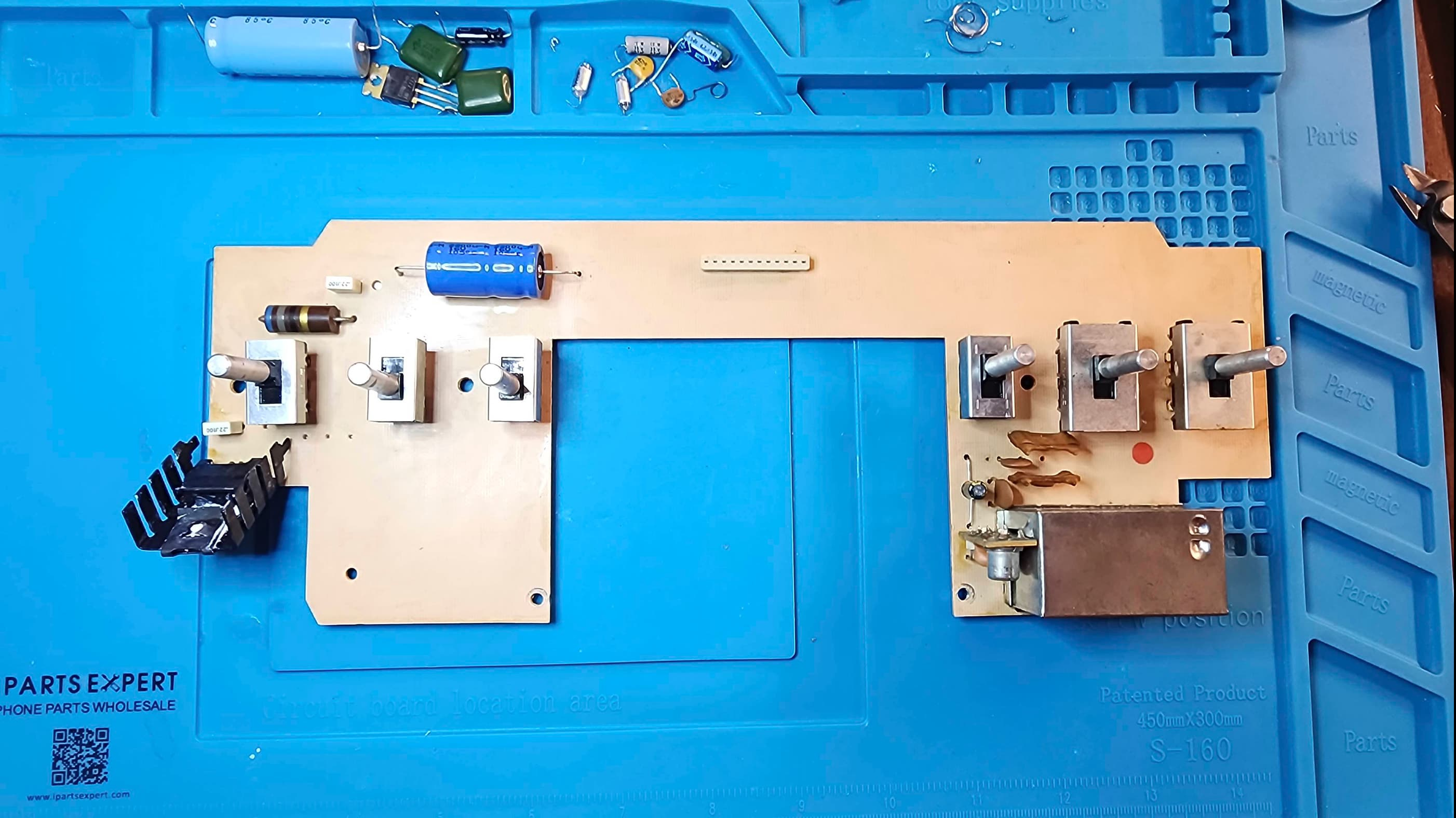
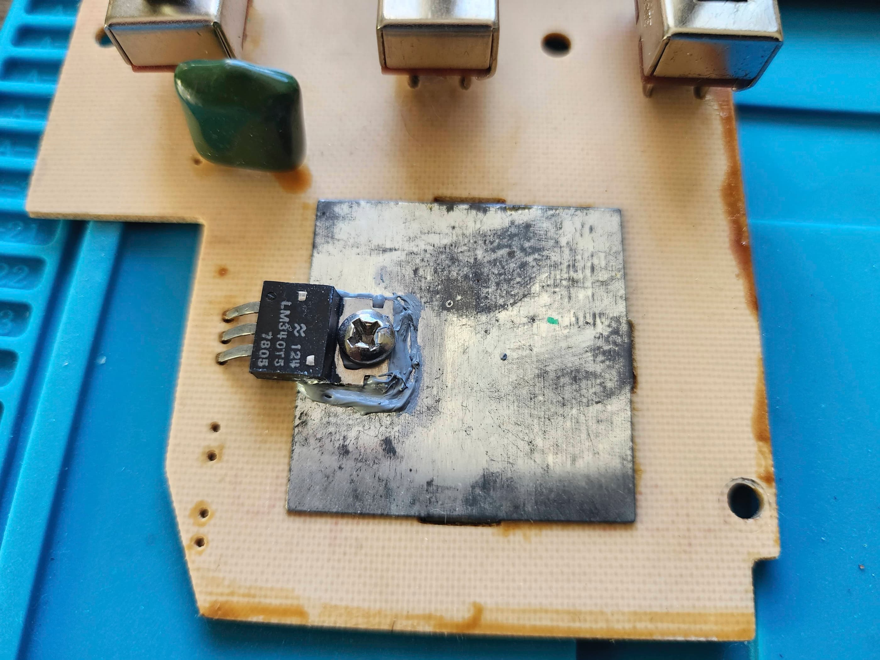
Once I had taken everything apart, I set to work on re-capping the entire unit along with: replacing the 7805 voltage regulator; performing the recommended mylar capacitor replacement on the upper board; the recommended anti-static Zener diode mod on C236 and C237 on the main board; and finally, the recommended polystyrene audio capacitor replacements also on the main board.
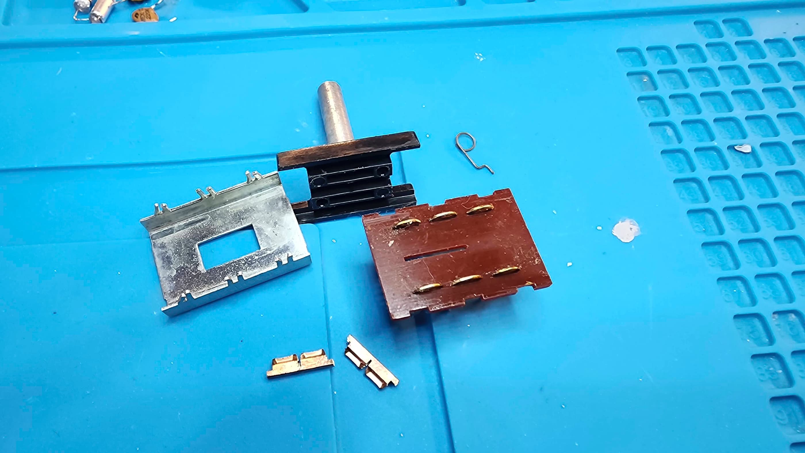
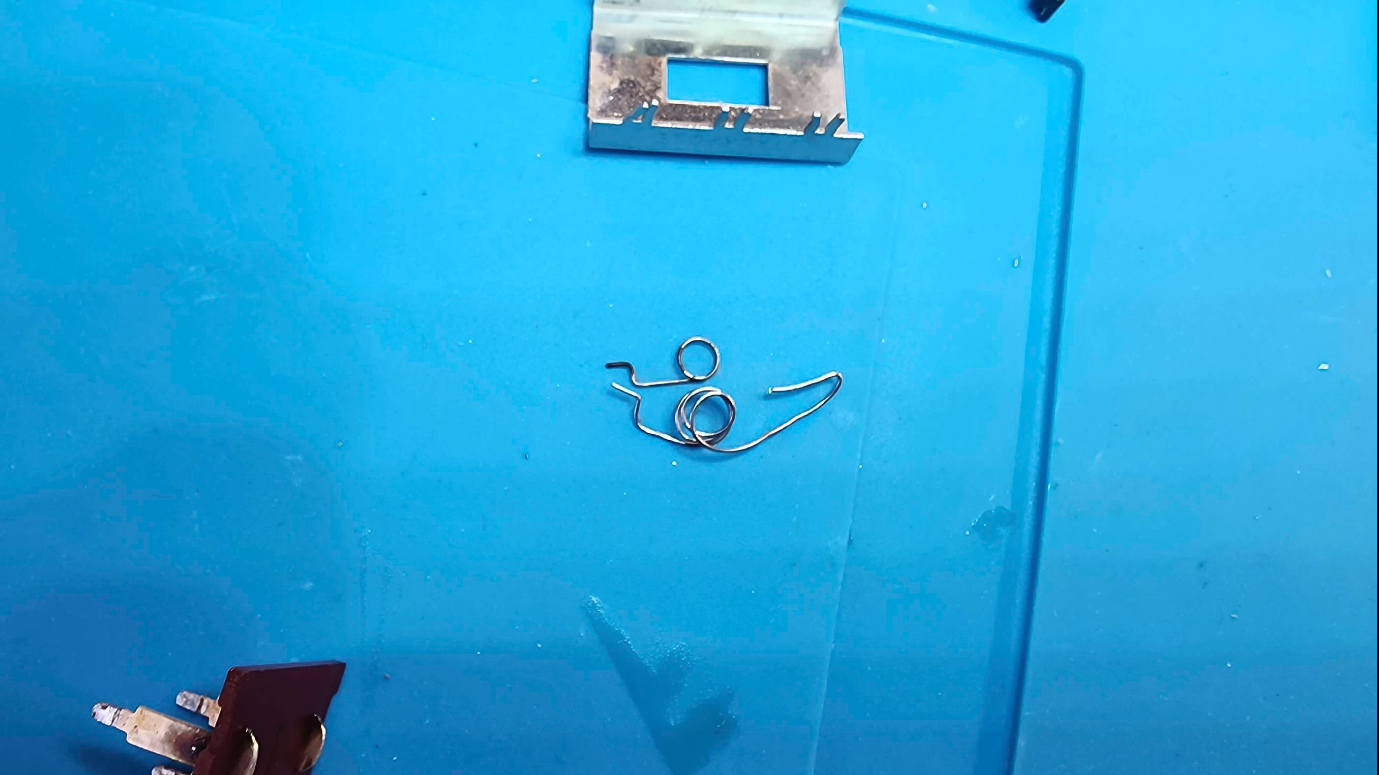
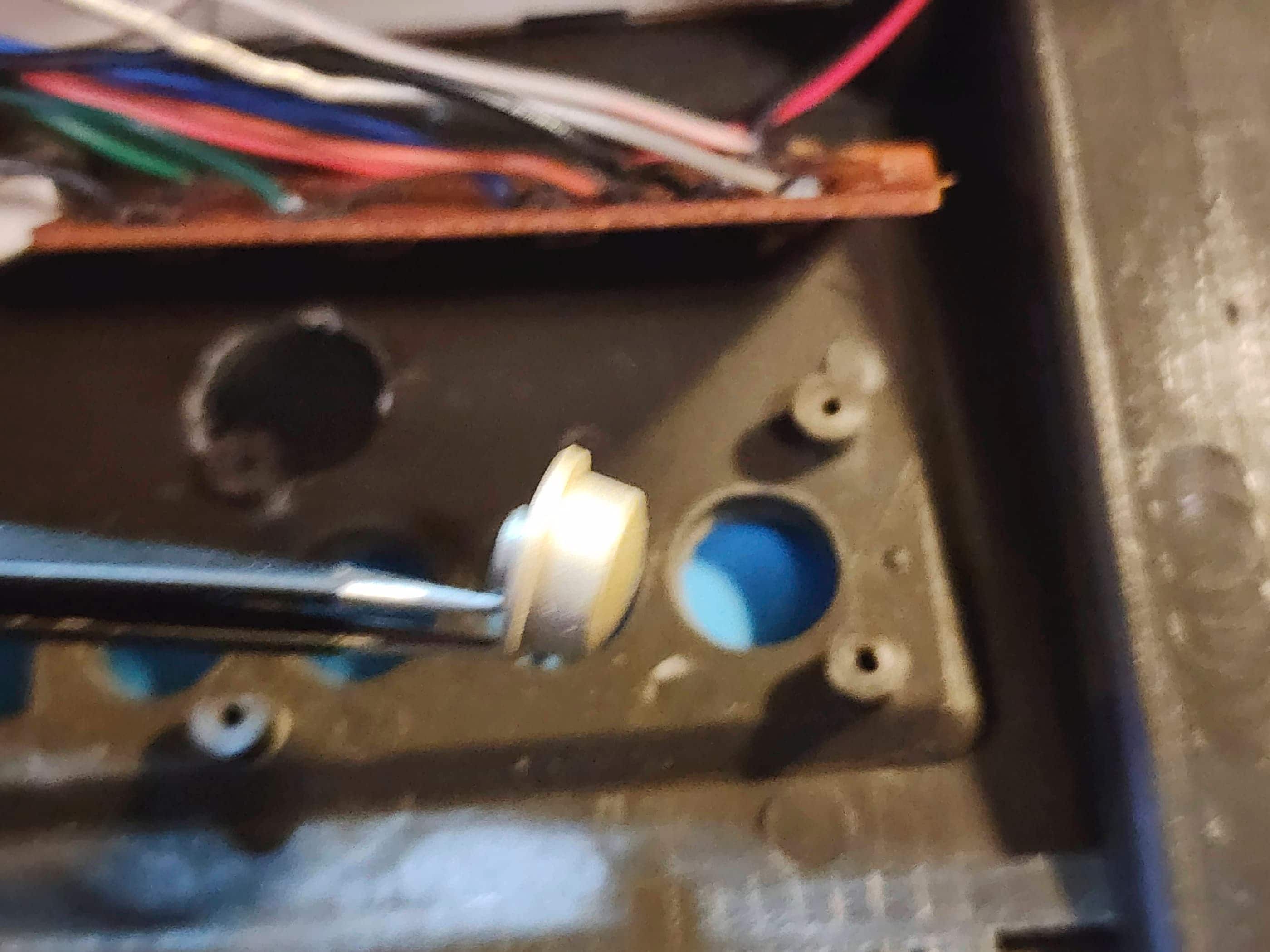
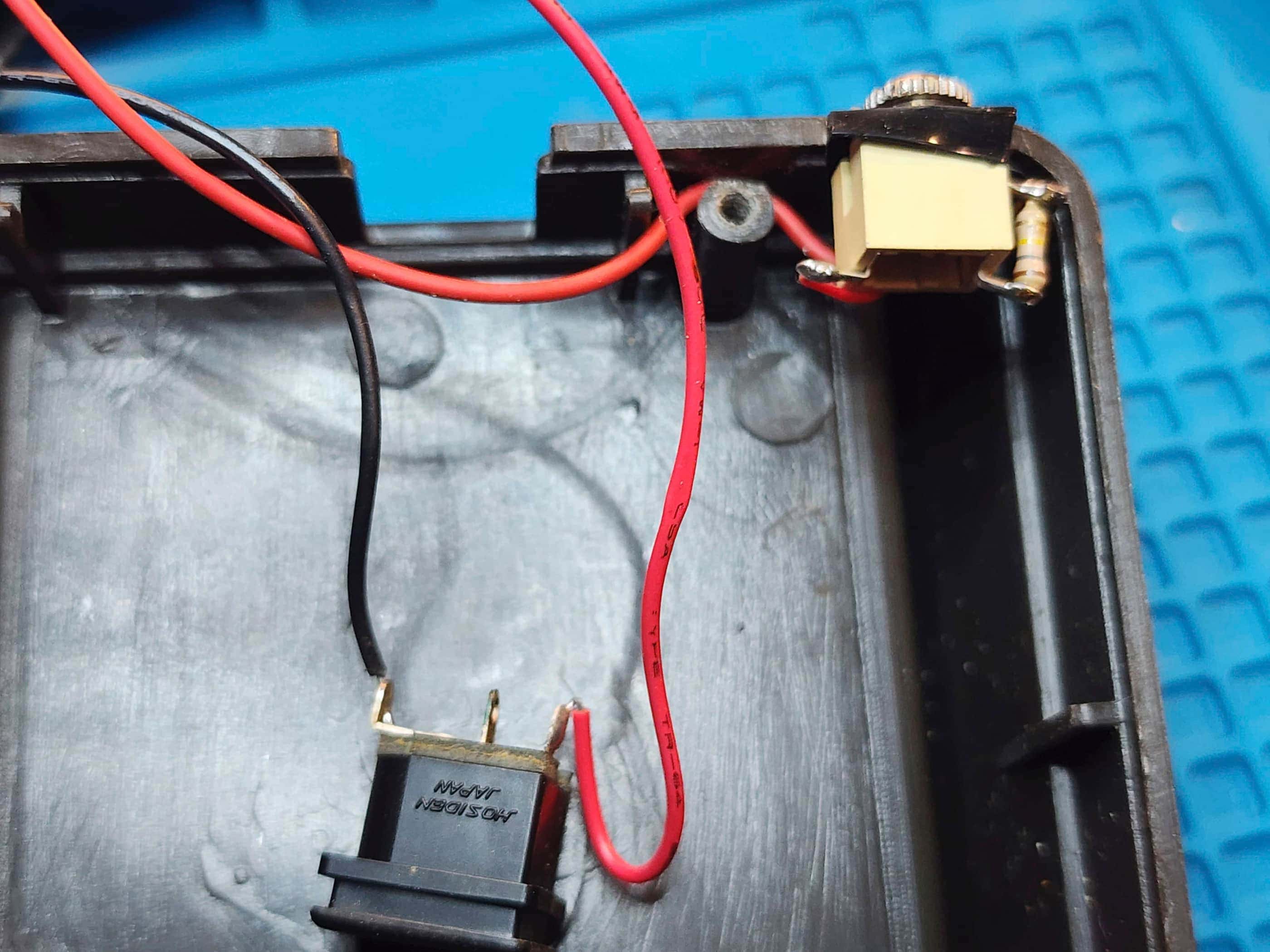
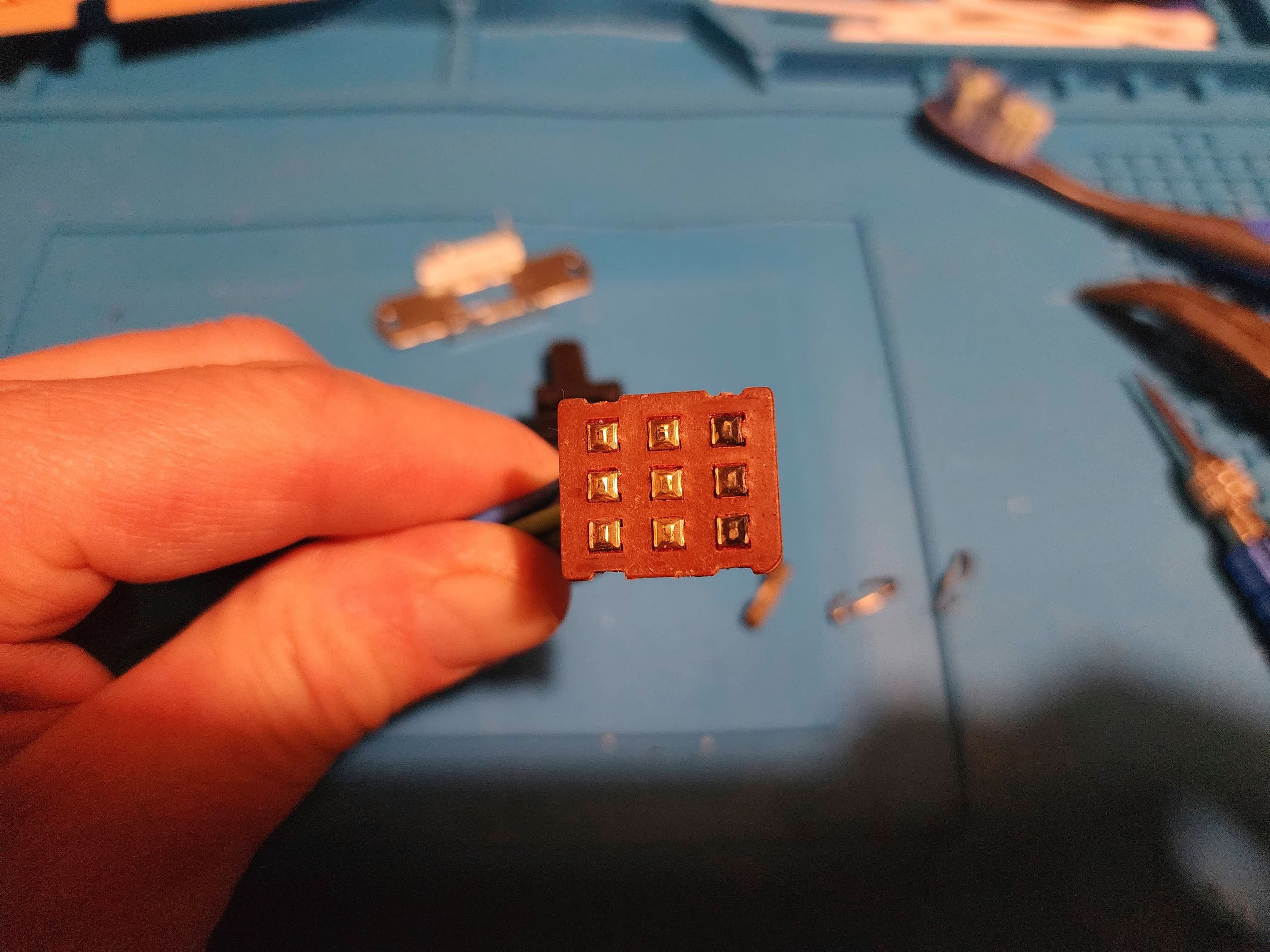
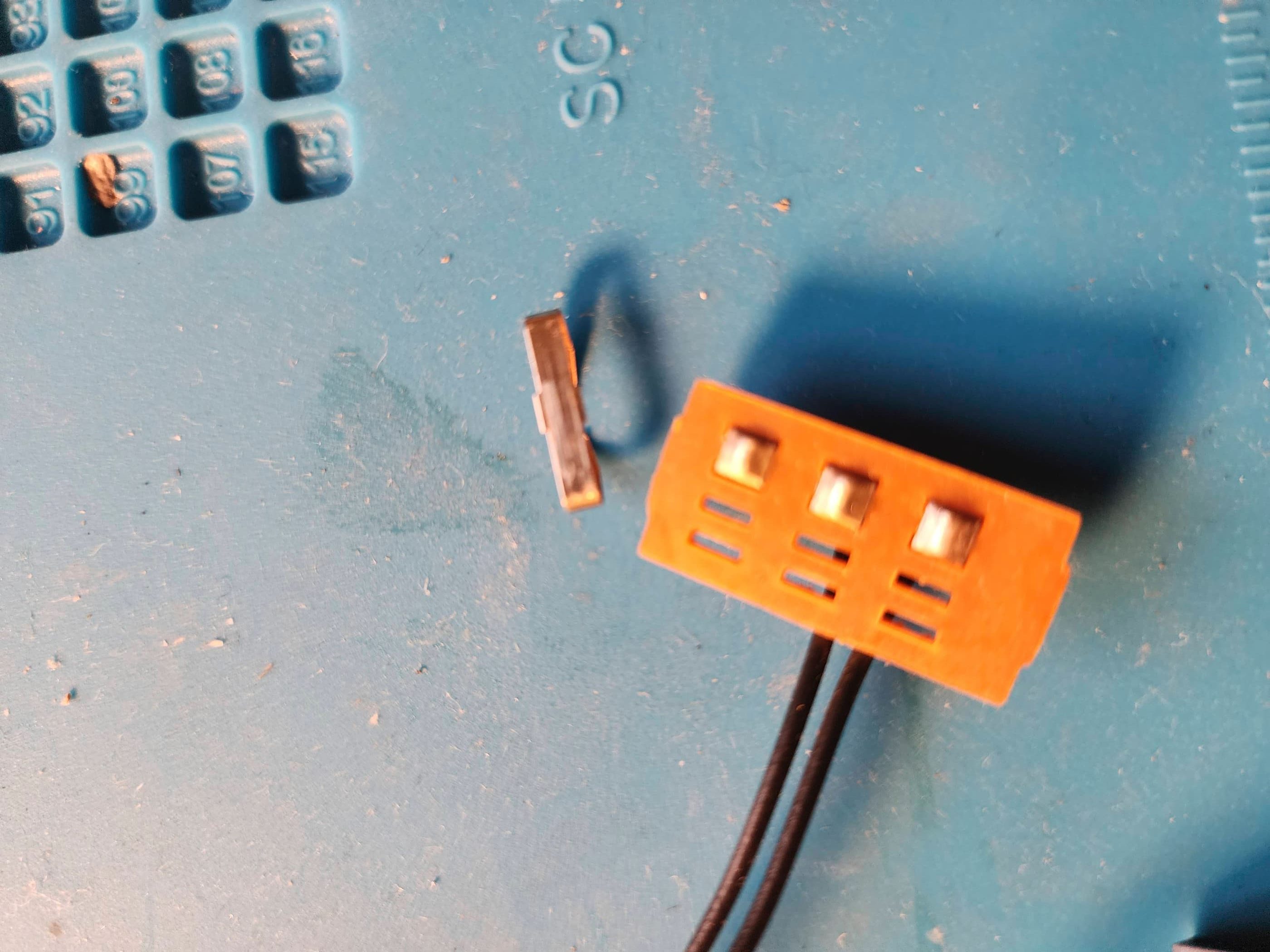
Once this was done, I then removed all the socketed chips, applied Deoxit D5, and then reseated them. I then began to work on trying to find a solution to fix the broken spring on the Game Select switch. My solution was to rummage through my parts bin where I came across a spring from a Commodore 64 keyboard. After 45 minutes or so of bending and carefully reshaping, I was able to fabricate a working replacement. I then reassembled the switch and soldered it back onto the board.
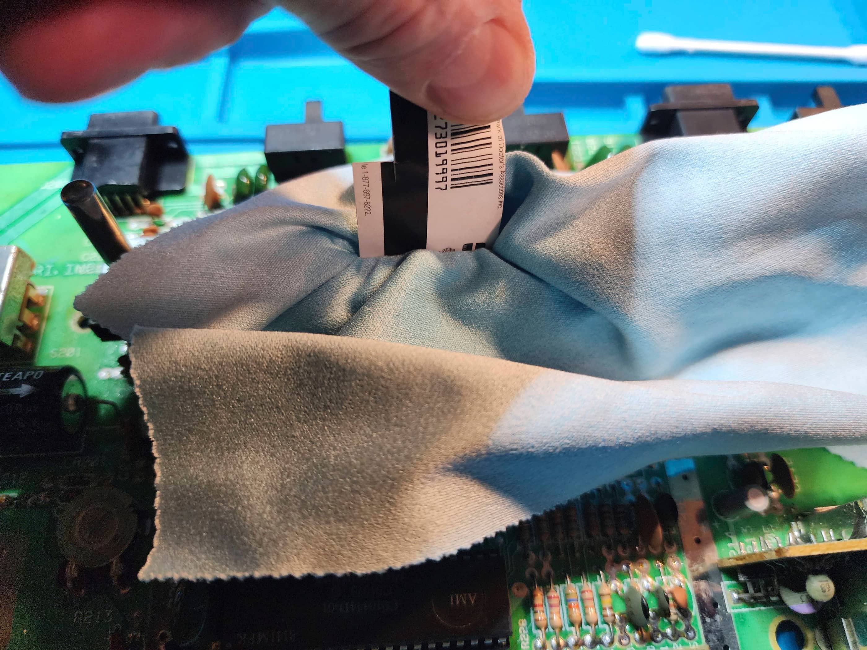
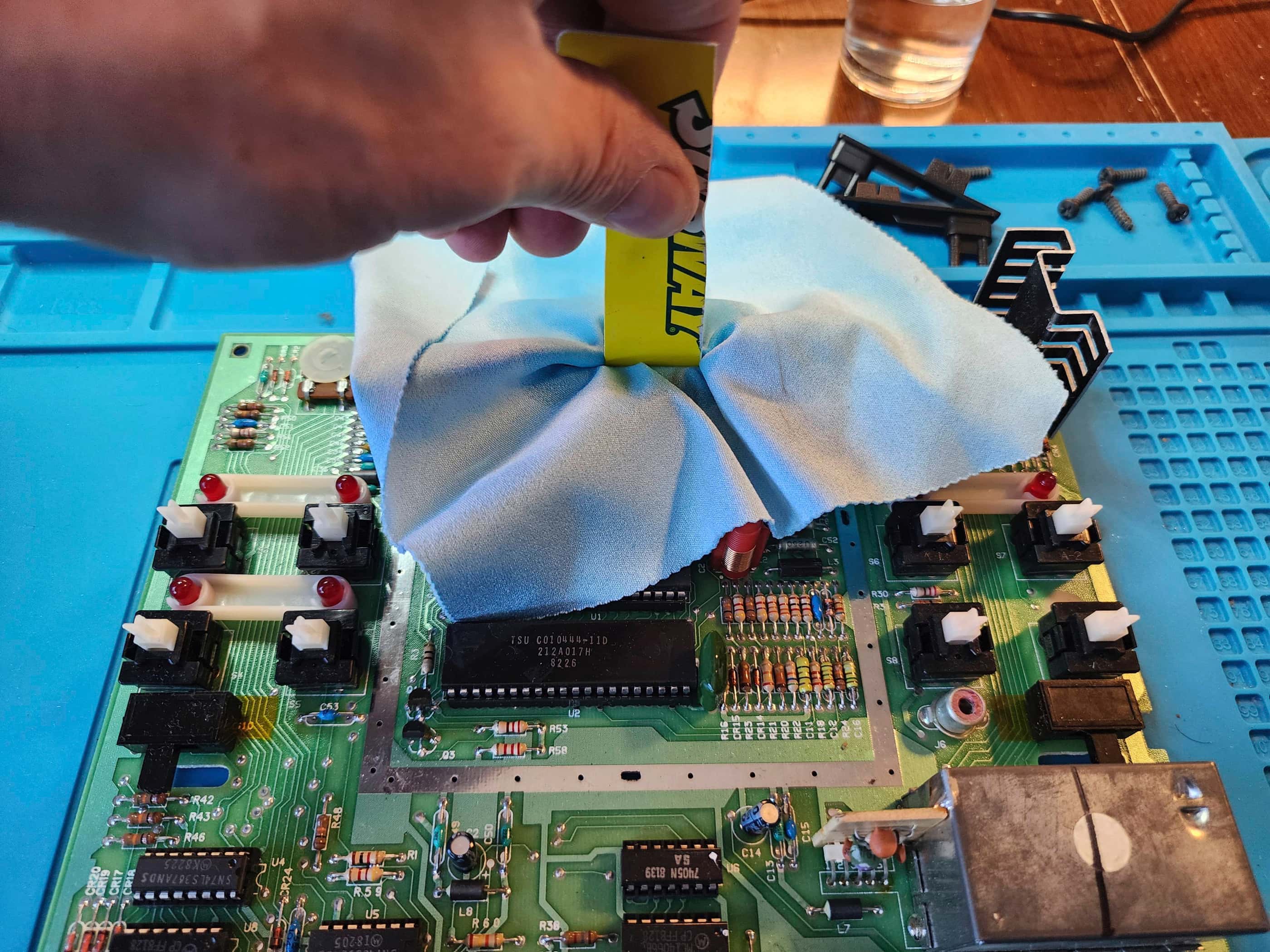
Before putting everything back together, I gave the boards and the case a thorough cleaning followed by a polish with Chemical Guys Natural Shine UV protectant. I then put the boards back together and began testing. As everything seemed to work, I then made some minor corrections to the colour using the adjustment pot on the main board and I also tweaked the RF modulator to improve the output; though it was still not fantastic.
Once everything was back together, I continued to try several more games, and was pleased to see that the Game Select switch continued to function perfectly. I also made sure to test both joystick ports and all other switches.
Parts & Products Used: 99% isopropyl alcohol; Chemical Guys Natural Shine; Deoxit D5; thermal paste; electrolytic capacitors (axial): 16v 2200μF (1); electrolytic capacitors (radial): 35v 4.7μF (2); ceramic capacitors: 220pF (2); polyester film capacitors: .22 μF 100v (2); polystyrene capacitors: 820pF 50v (2); 7805 5v regulator; Zener diodes (2)
Atari Video Computer System (VCS) “Light Sixer” (CX-2600)
Years (1978 – 1980)
Interesting fact: This was my second-ever game console. 🙂 It’s called a “Light Sixer” because when it was released in in 1978, it was significantly lighter (1.52 kg) than the original Atari VCS (2.05 kg) that debuted the year before. The reason for this was the significantly reduced thickness of the plastic base. “Sixer” comes from the six toggle switches on top of the console. (source)
Condition When Acquired: Fully Functional
Current Condition: Fully Functional


Project Details: The previous owner(s) of this system took excellent care of it! There was little I needed to do, other than give it a good cleaning (someone had a dog in their house). It and all its accessories were in fantastic condition and the entire package came stored in a smoked plastic case from the late 70s / early 80s. After pulling the system apart for inspection and cleaning, I applied new thermal paste to the voltage regulator. As it was in such good condition, I found some original manuals and documentation on Etsy to bring the system as close to new as possible; sans the original box
Parts & Products Used: 99% isopropyl alcohol; Chemical Guys Natural Shine; Bar Keepers Friend (for polishing the switches); thermal paste
Atari VCS CX-2600A
Years (1981 – 1982)
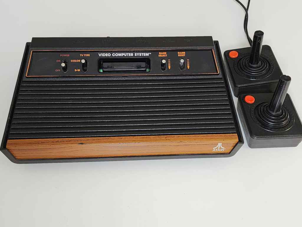
Interesting fact: The CX-2600A was a revision to the VCS that was released in 1980. The motherboard was redesigned to be a single unit and the two difficulty switches on the light sixer, were moved to the back of the console. Hence, the 4 switches now on the front. (source) The CX-2600A is one of the most common types of 2600 because it was released during the height of Atari’s popularity. (source)
Condition When Acquired: Non-Functional (DOA)
Current Condition: Fully Functional


Project Details: I couldn’t pass on picking up this “untested” 4 switch CX-2600 A. Not only did I not have one in my collection, but for $60, it included 4 Atari joysticks and a Slik Stik joystick, which was my ‘go to’ when I had my Commodore 64 back in the 80s. 🙂
The console was quite dirty and since it didn’t come with a power adapter, I used a new Jameco 9V 500mA that I had waiting in the wings. After putting in one of my test cartridges, I powered the unit on and was pleasantly surprised to see the sights and sounds of Missile Command come onto the screen. However, it didn’t last long as the video output launched into a systematic flickering; though pulsating may be a better descriptor. Every second the screen would go to static and then back again, making it completely unusable.
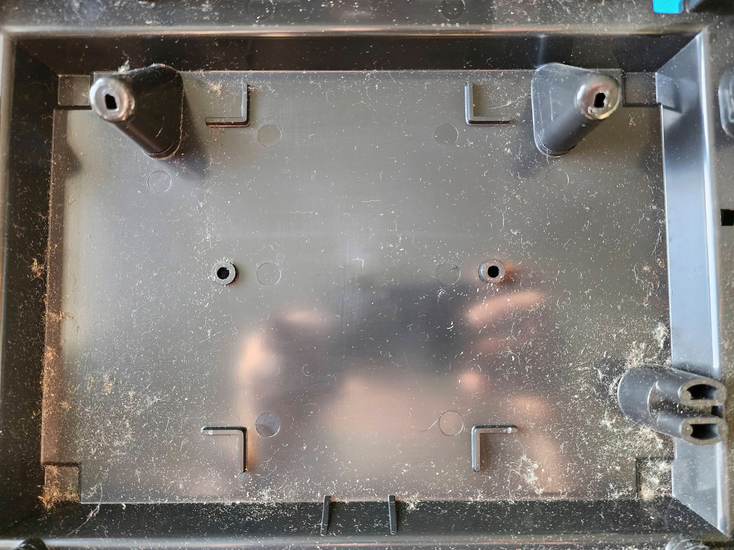
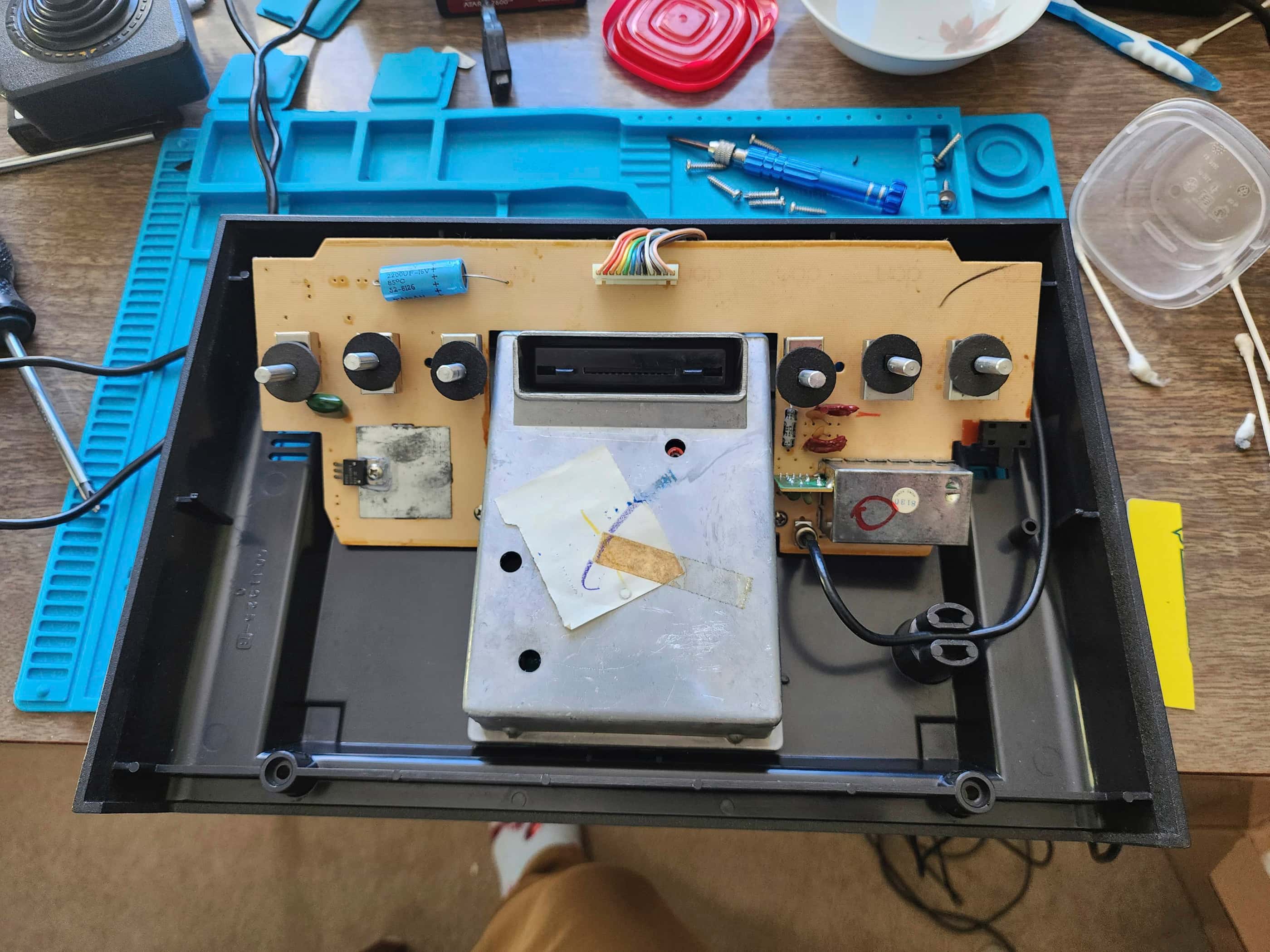
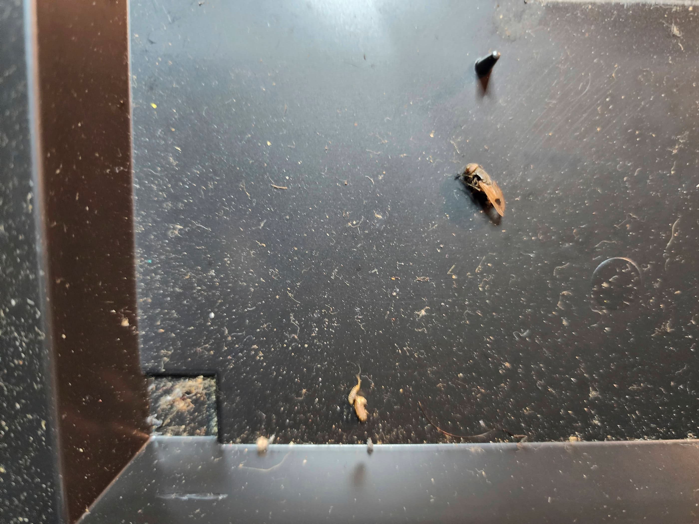
I then disassembled the console and in doing so, noted amongst the dust and hair (yes, hair), several dead bugs. Yuck! 🤮 After removing the motherboard, I then gave the case a thorough wash in hot water. With the case set aside, I then began to inspect the board. When I powered the unit back on, the pulsating continued and so I tried adjusting the RF modulator with no success. Not sure if this was related to bad voltage, a bad TIA chip, or a bad RF modulator, I thought start with voltage testing.
Sure enough, the output of the 7805 was lower than 5V, but it was close enough that it shouldn’t have made a difference. Voltages on the MPU, RIOT, and TIA chips were also within range, as was the voltage on the RF modulator. I then proceeded to remove the original 7805 and while I was at it, thought I may as well just remove all the electrolytic capacitors along with the styrene audio caps and the poly film ones. Unfortunately, I didn’t have any Zener diodes and capacitors to complete the anti-static update for Rev 13, so I’ll do that another day. I also disassembled and cleaned the power switch for good measure. Once I’d replaced all the parts, I powered the unit back on and… it was still pulsating, only now it didn’t display any colour. Hmmmm… off to Atari Age I went… 🤔
Still trying to eliminate any possibilities, I removed and cleaned both the colour/B&W switch and the channel select switch. I also removed the RF modulator and re-soldered it back into place. I then powered it on and… nothing changed. I then removed, inspected, and reseated the TIA chip and reflowed the solder to all the chips. Still nothing.
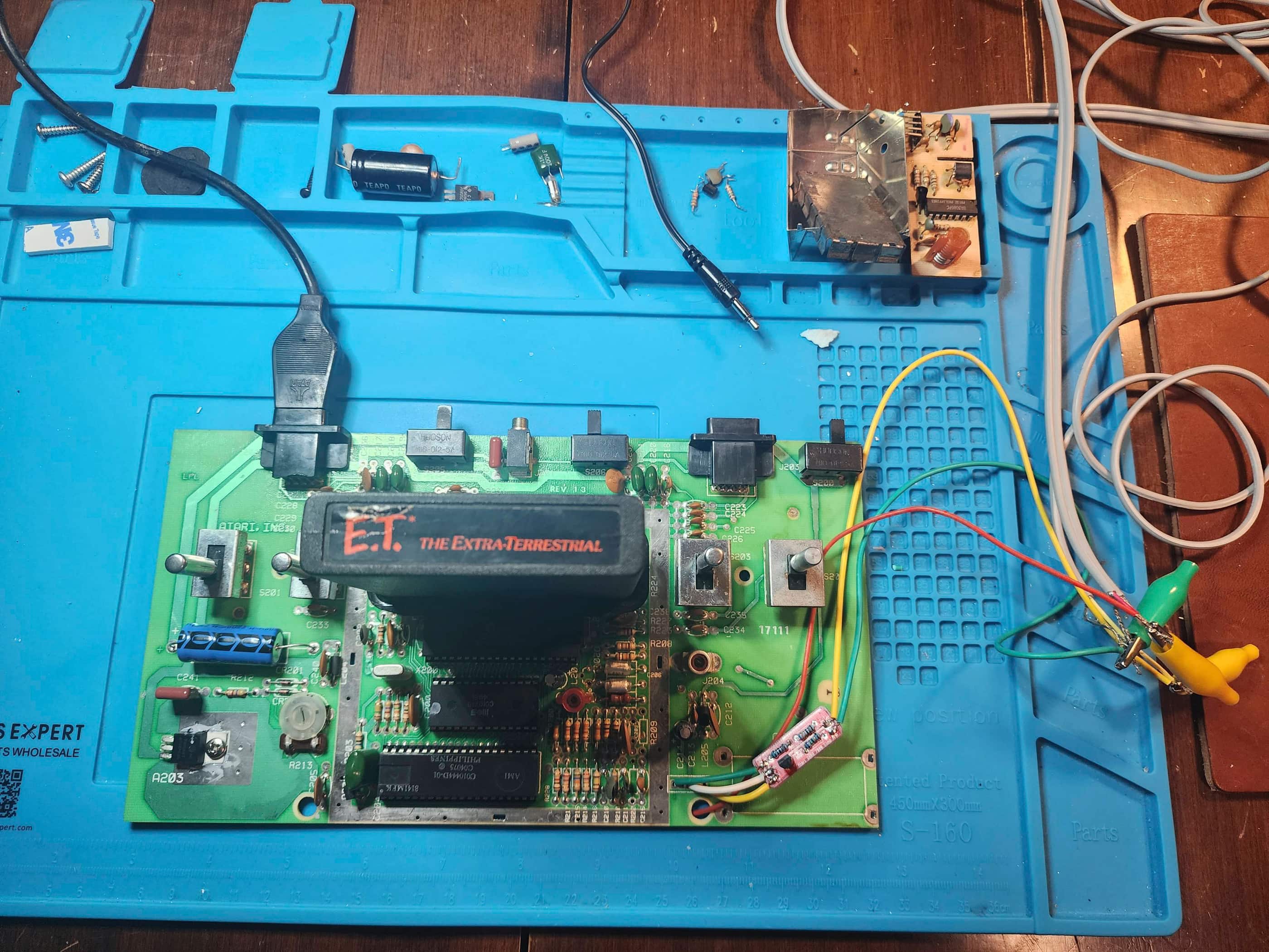
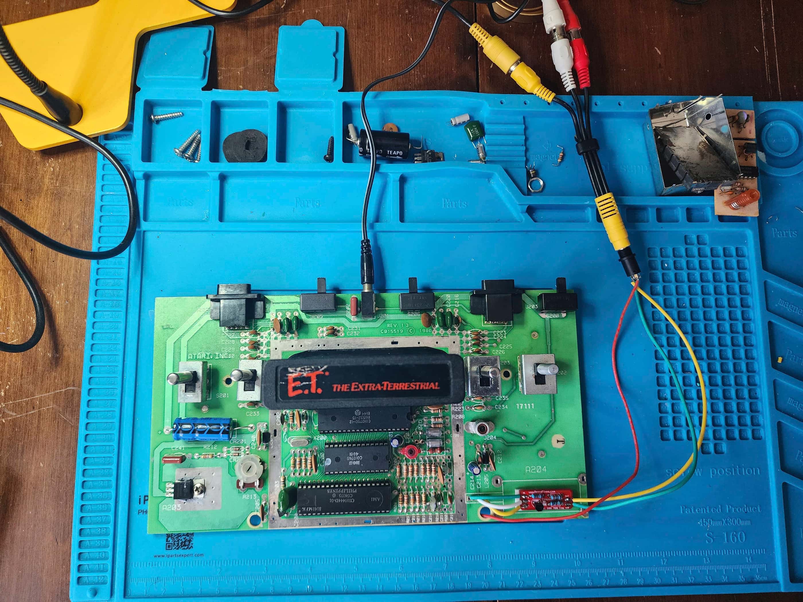
I then remembered that I had ordered in a Retrofixes’ 2600/7800 composite mod board a long time ago. I dug it out of my parts bin and after removing the RF modulator, I installed the mod and then tested the output wires before installing them onto the jack. Success! The unit sprung to life with clear video and sound. The problem was solved! 😀
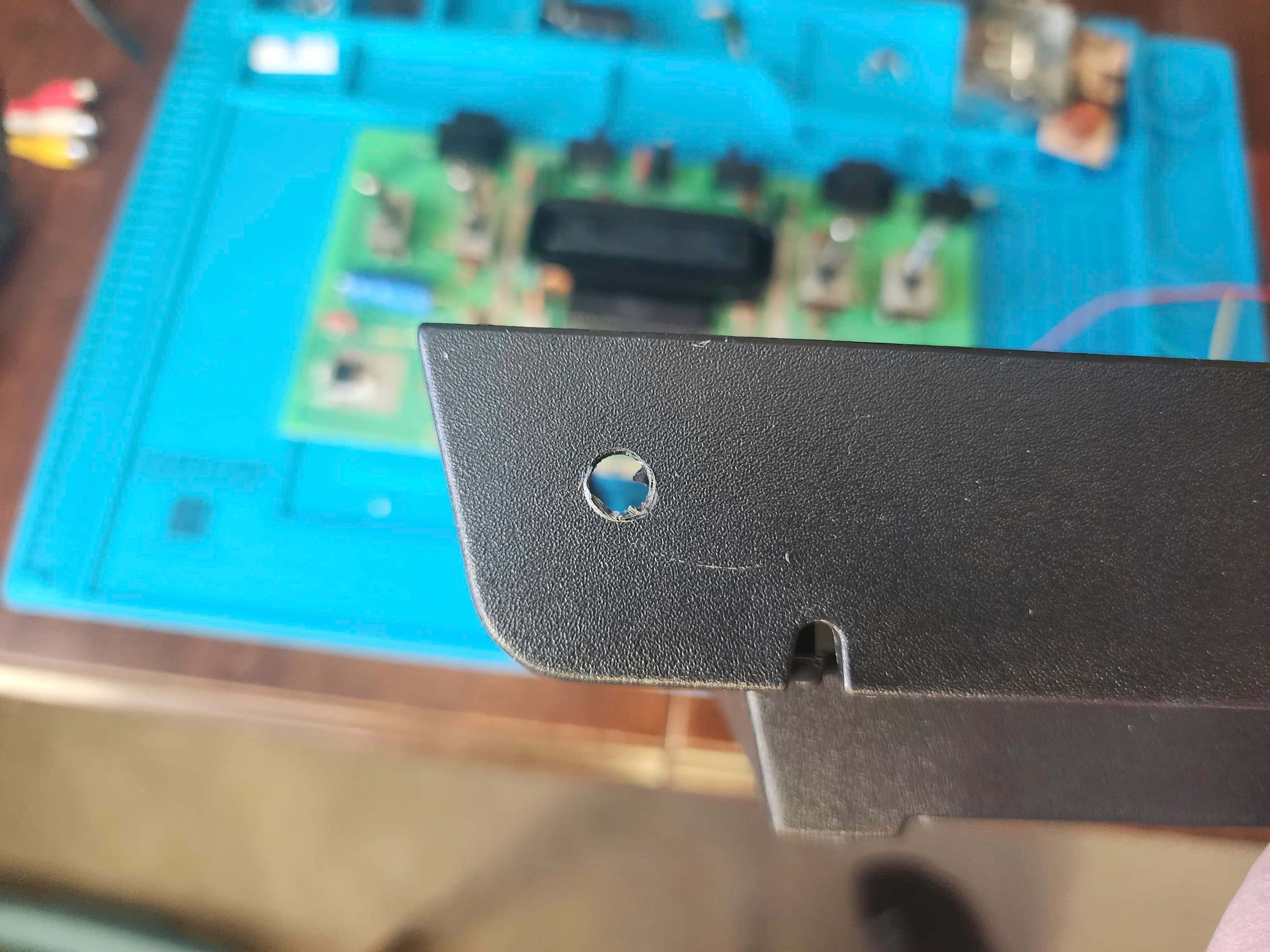
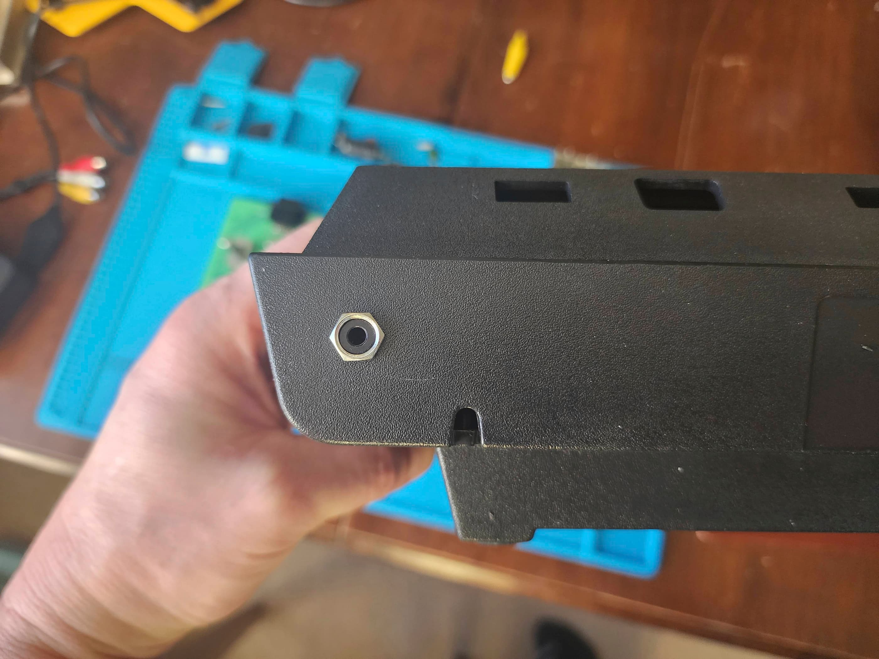
I didn’t have any RCA jacks on hand, but I did have a number of 3.5mm TRRS jacks, so this is what I used. To be honest, I like that a single, small TRRS jack doesn’t take too much away from the aesthetics of a console and with this unit, it blended in nicely. I then wired the jack to fit one of a number of short 3.5mm to female RCA jack cables that I had on hand. As the 2600 only kicks out mono for audio, I joined the left and right pins together.
Also, I think that next time, I will keep some perf board on hand so that I could try and make a comp board as the schematics for many consoles, and in particular Atari 2600s, are all over the internet. I’d even like to see if I could repurpose the RF board in some way to create one, perhaps removing all the components, cutting traces and then soldering bypass wires to new components, just to see if it could be salvaged…
Anyway, I reassembled everything except I didn’t put the RF shielding back on because several of the tabs had broken off during disassembly. I then shined it up and tested everything out. I’m now the proud owner of a fully functional, 4 switch Cx-2600 A. 😀
Parts & Products Used: 99% isopropyl alcohol; Chemical Guys Natural Shine; electrolytic capacitors (axial) – 16v 2200μF (1); electrolytic capacitors (radial) – 50v 4.7μF (2); poly film capacitors – 100v .22 μF (2); styrene audio capacitors – 820pF (2); 7805 5V 1A voltage regulator; Retrofixes.com Atari 2600 composite mod kit; 3.5mm TRRS jack (1); 6” 3.5mm to RCA female adapter (1); Jameco 9V 500mA power adapter; 22-gauge wire; thermal paste; dielectric grease

Atari CX-2600 “Darth Vader”
Years (1982 – 1983)
Interesting fact: The nickname ” Darth Vader” comes from the all-black design. It was also the first Atari that was called the 2600 rather than the Video Computer System (VCS). (source)
Condition When Acquired: Fully Functional
Current Condition: Fully Functional


Project Details: This system also came with my INTV System III (#1) as a lot. The original owner was selling both units and did not know if either worked. Apparently, the last time they were played was in the mid-90s and both had been in storage since. As the Atari did not come with a power adapter, I used an existing one that I knew worked. I plugged in Yar’s Revenge, turned the unit on and… it worked perfectly! As the machine was quite dirty (including some dead bugs inside) I spent extra time cleaning it. I also applied new thermal paste to the regulator and added a replacement power adapter. This cool-looking system now looks like new and plays like new. 😁
Parts & Products Used: 99% isopropyl alcohol; Chemical Guys Natural Shine; thermal paste; replacement 9v 500mA power adapter

Atari 2600 Junior “Short Rainbow” (CX-2600)
Years (1986 – 1992)
Interesting fact: After Atari was sold in 1984 to Jack Tramiel (founder of Commodore computers), it re-released a smaller version of the 2600 commonly referred to as the 2600 Junior. Two variations were released, one with a short rainbow on the logo and one with a long rainbow. (source)
Condition When Acquired: Non-Functional (DOA)
Current Condition: Fully Functional


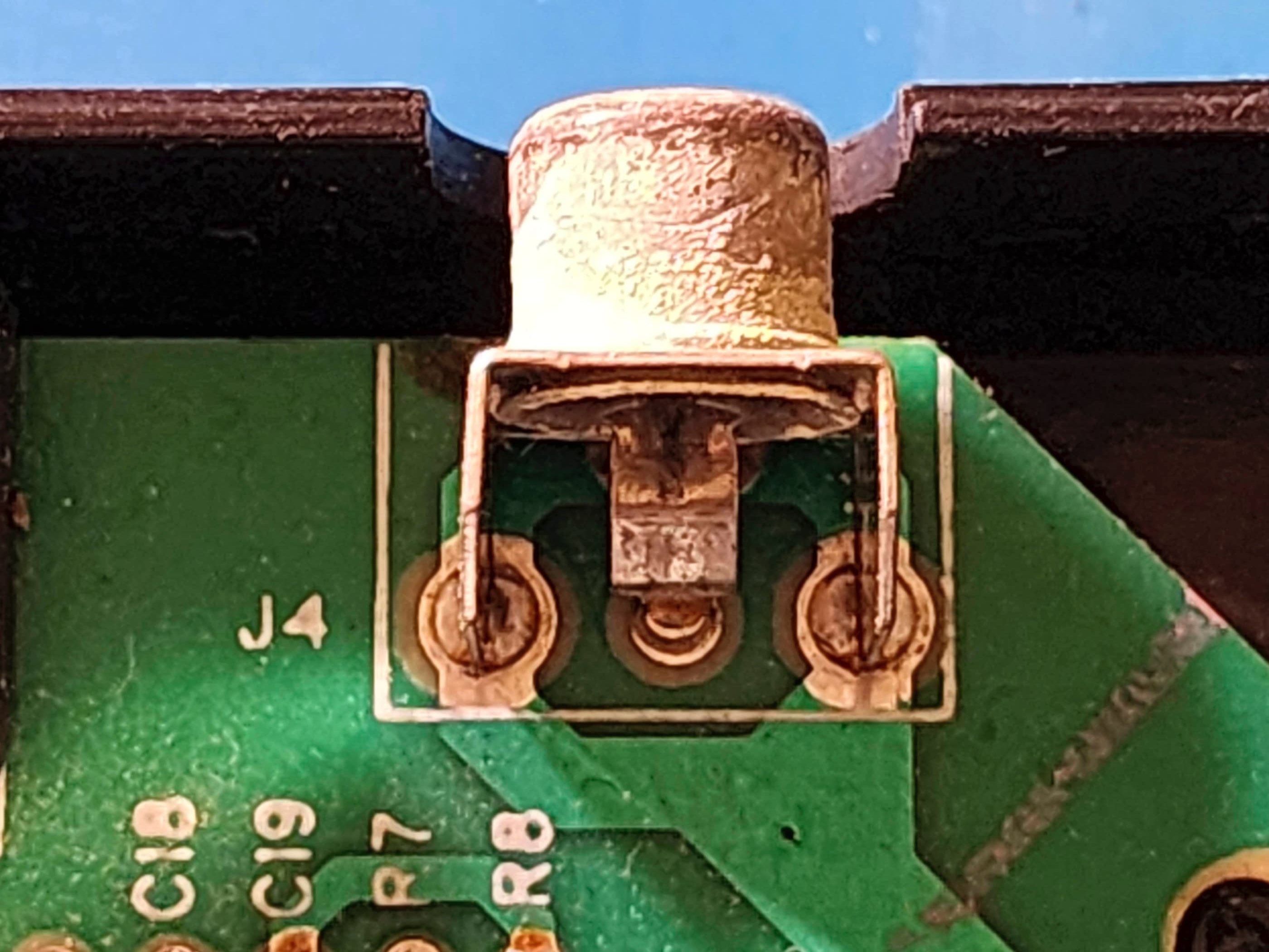


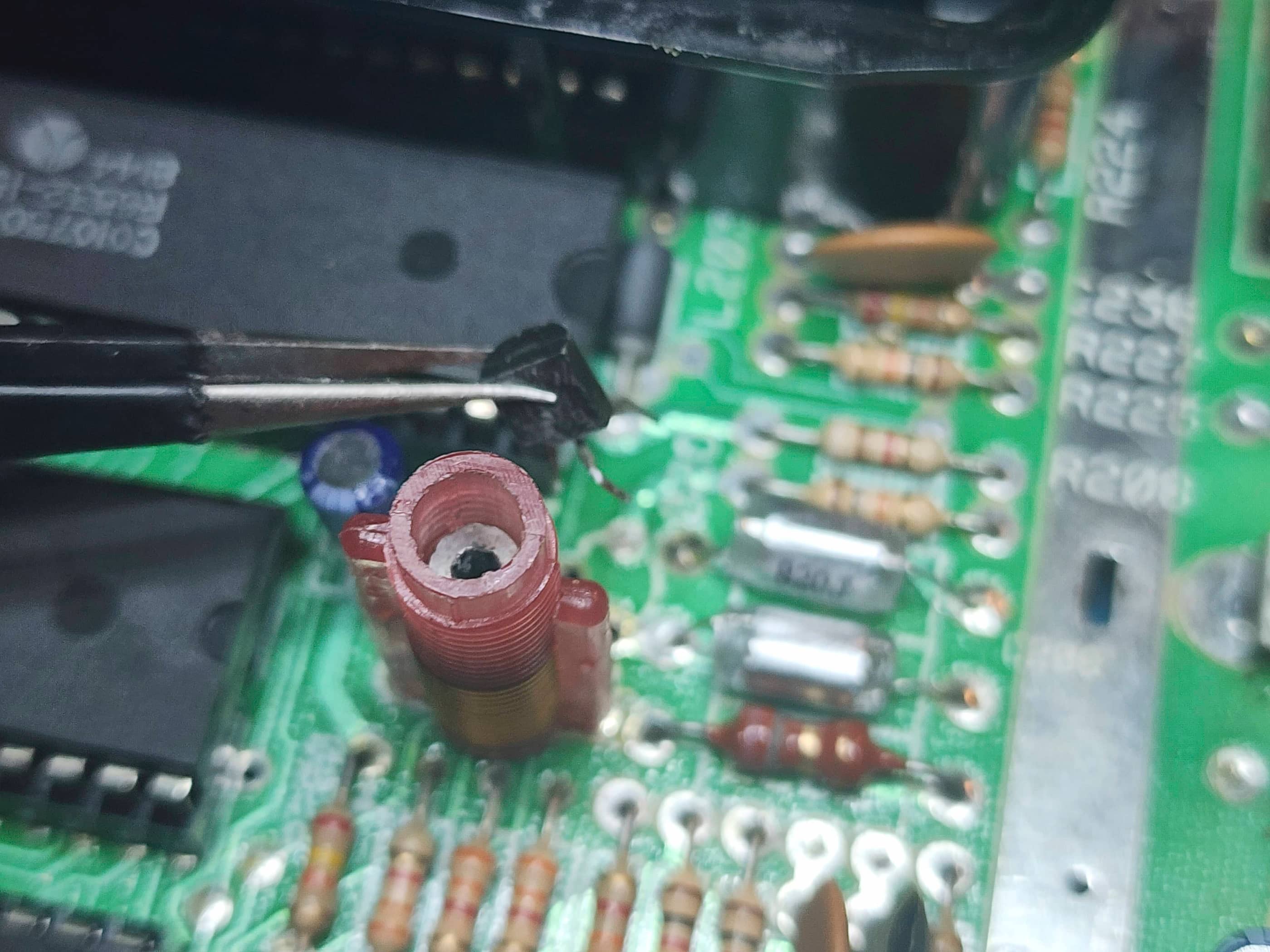
Project Details: This unit was DOA. When I opened it up, I discovered three immediate concerns: 1) the 7805 5v regulator was not screwed onto the board; 2) the power jack was damaged and the barrel of the adapter was not seating properly; and 3) the RF output jack was in poor shape. I applied some thermal paste and screwed the regulator onto the board and powered the unit on, but no dice. The system was still dead. I then began continuity and voltage testing to confirm that the regulator was the problem and that it wasn’t a bad trace or loose solder. After determining it was the regulator (a very common problem) I replaced it with a new one and the unit powered on – success! 😀 However, the loose power jack was still a big concern and the output signal was snowy. I put an order to Console5 for a new power jack and a gold-plated RF jack. I contemplated putting in a composite mod, but my preference is always to try and restore systems to be as close to the original as possible. Once the new parts arrived, I replaced the power jack, the RF jack, and then re-capped the entire board just to be safe, using a 50v 4.7μF capacitor to replace the original 35v 4.7μF one (you can go up a value voltage but the μF must stay the same). Curiously, the board only had two electrolytic capacitors while my Atari Jr. “Large Rainbow” had five. I powered the unit on and it worked without a hitch. I then performed my usual cleaning regiment and the system now looks and functions like it was meant to. 😁
Parts & Products Used: 99% isopropyl alcohol; Chemical Guys Natural Shine; thermal paste; gold plated right angle RF jack (1); DC power jack (1); 7805 +5v regulator (1); electrolytic capacitors (axial) – 16v 2200μF (1); electrolytic capacitors (radial) – 50v 4.7μF (1); replacement 9v 500mA power adapter

Atari 2600 Junior “Long Rainbow” (CX-2600)
Years (1986 – 1992)
Interesting fact: Outside of having two variations with different rainbows, the 2600 Junior was much smaller than previous versions and instead of including a built-in RF cable, it featured a plug-in RF jack. (source)
Condition When Acquired: Non-Functional (DOA)
Current Condition: Fully Functional


Project Details: This system came cheap with an original Atari 2600 box, except the serial number on the console did not match the number on the box. After confirming the power adapter was working despite having been spliced at some point in time, I inserted a cartridge and turned the unit on. I was instantly met with a grey flickering screen and loud screeching. Hmmm… 🤔 I opened the console, removed the RF shielding, and used IPA to thoroughly clean the cartridge slot. For good measure, I also cleaned the pins on the cartridge. I powered the unit on and was pleased to see a grainy Missile Command pop onto the screen. I connected a joystick, started the game, and was further relieved when I heard the proper sounds. I adjusted the RF tuning on the board, but the picture still wasn’t right.
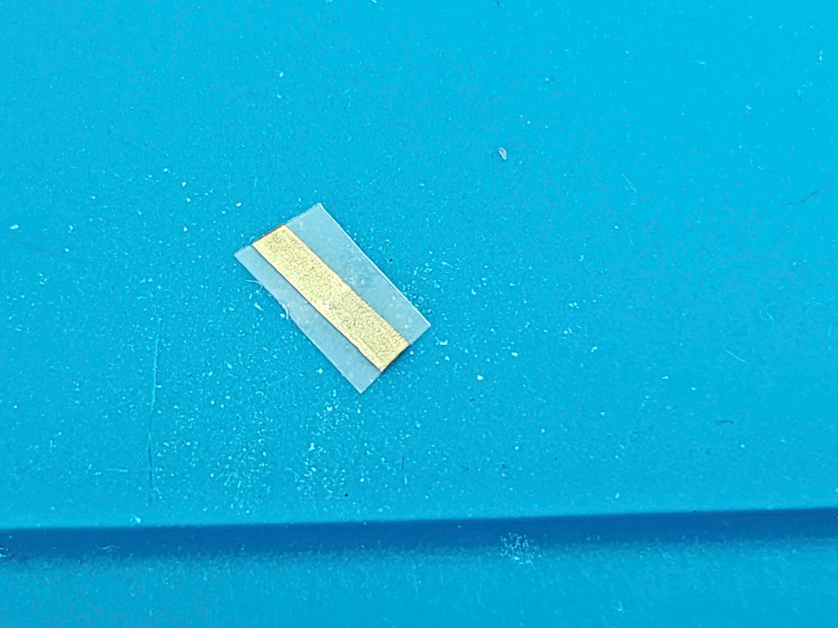
That’s when I examined the RF jack and discovered the end of the RF cable had more play within the jack then it should have. I then held the end of RF cable at a bit of an angle where it entered the receiving jack and this immediately fixed the issue. To confirm, I tried another RF cable and had the same result. Having a spare gold-plated RF jack on hand, I proceed to desolder the original and replace it. I also broke my rule-of-thumb and even though it didn’t need it, I re-capped the board. I did however, leave the voltage regulator alone; applying only new thermal paste. I removed the old electrical tape on the power adaptor cord, re-spliced the wires, and used heat shrink to cover them. Finally, I did my usual cleaning regiment and in the process, deliberately peeled off the cellophane that was still on the metal strip on the front of the casing. This made the unit look slightly more presentable. I also paired it with an era-appropriate Wico joystick as the unit didn’t come with an Atari joystick. The system now functions as it should. 😁
Parts & Products Used: 99% isopropyl alcohol; Chemical Guys Natural Shine; thermal paste; gold plated right angle RF jack (1); electrolytic capacitors (axial) – 16v 2200μF (1); electrolytic capacitors (radial) – 50v 4.7μF (4)

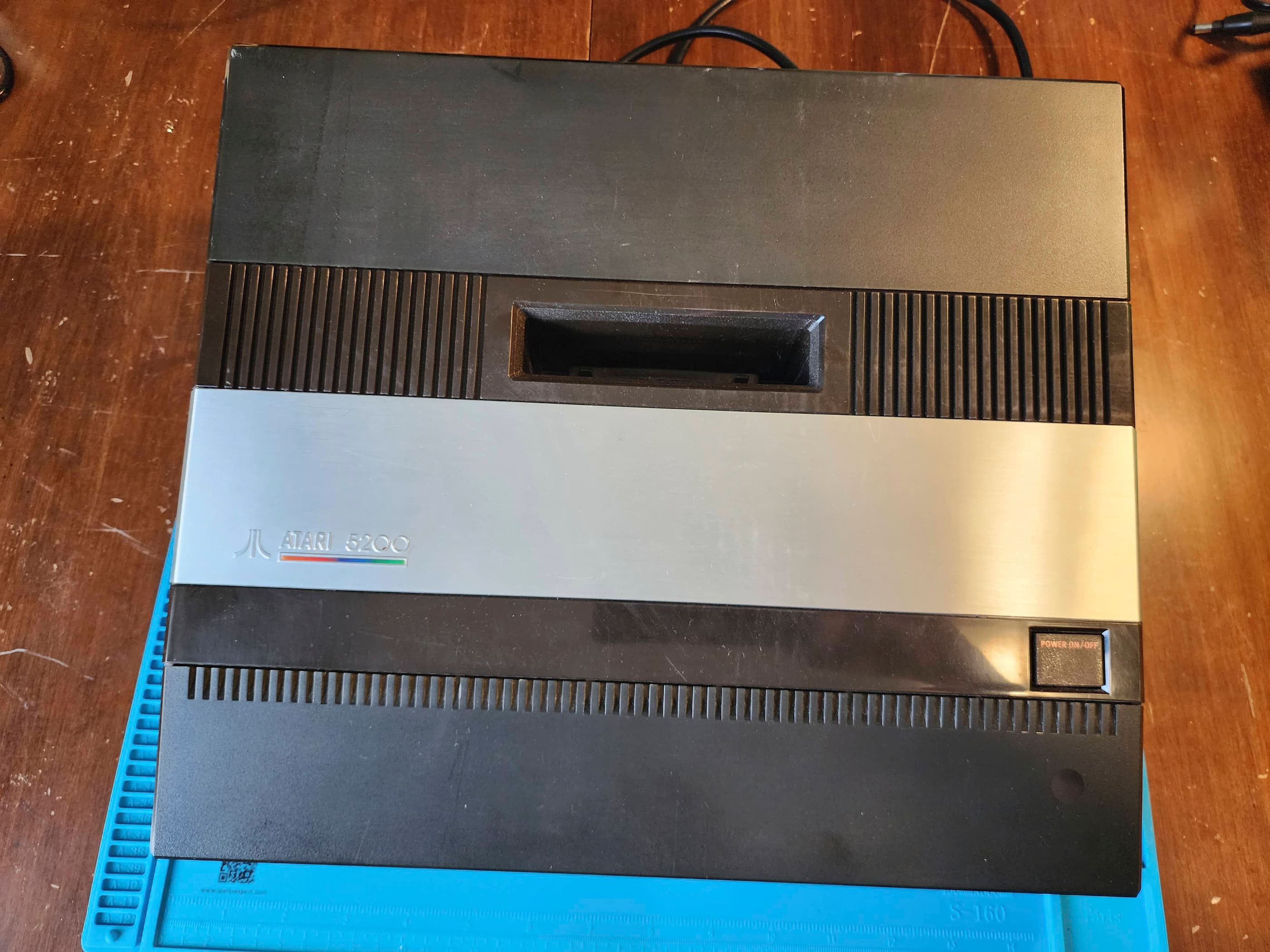
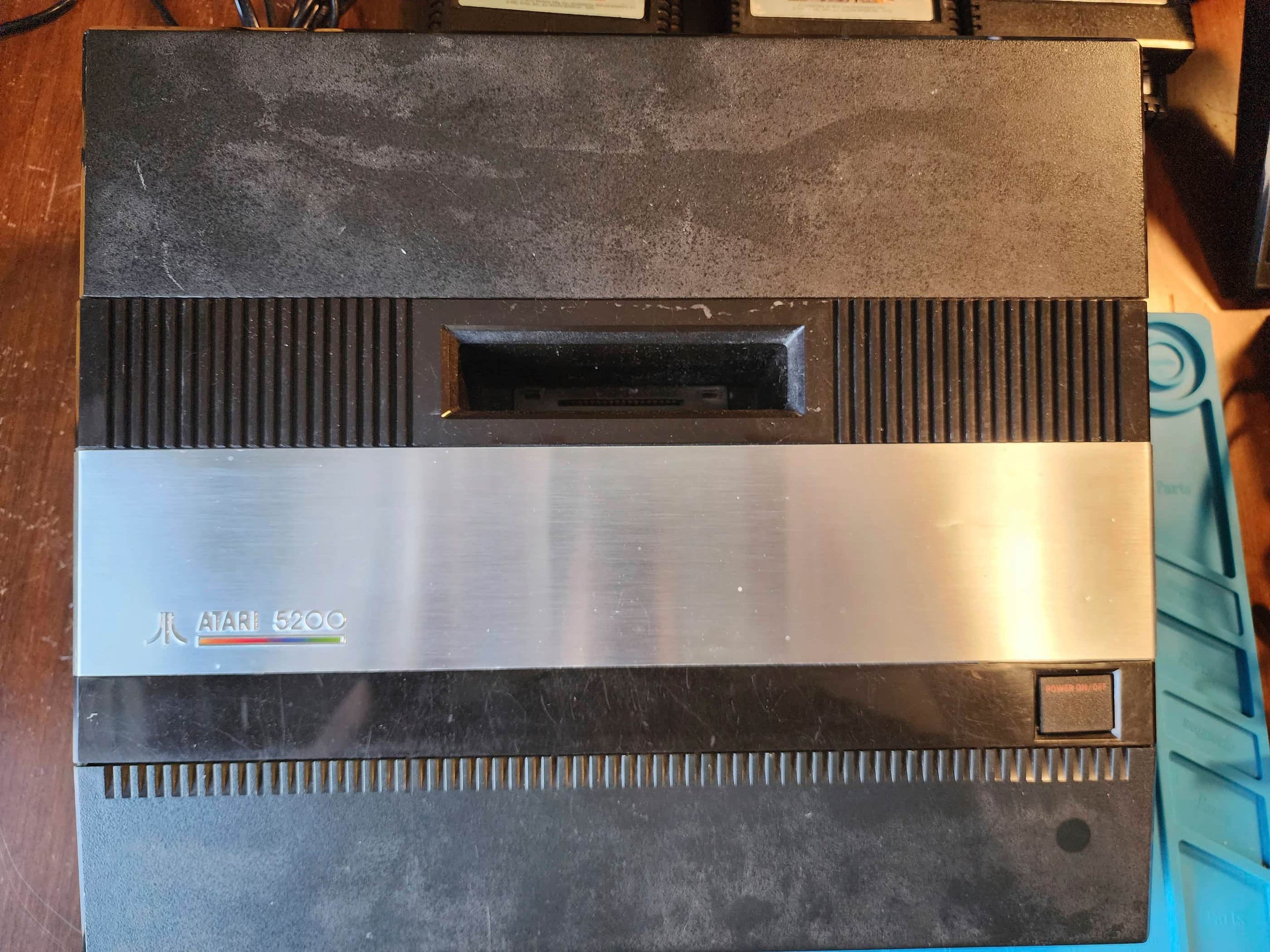
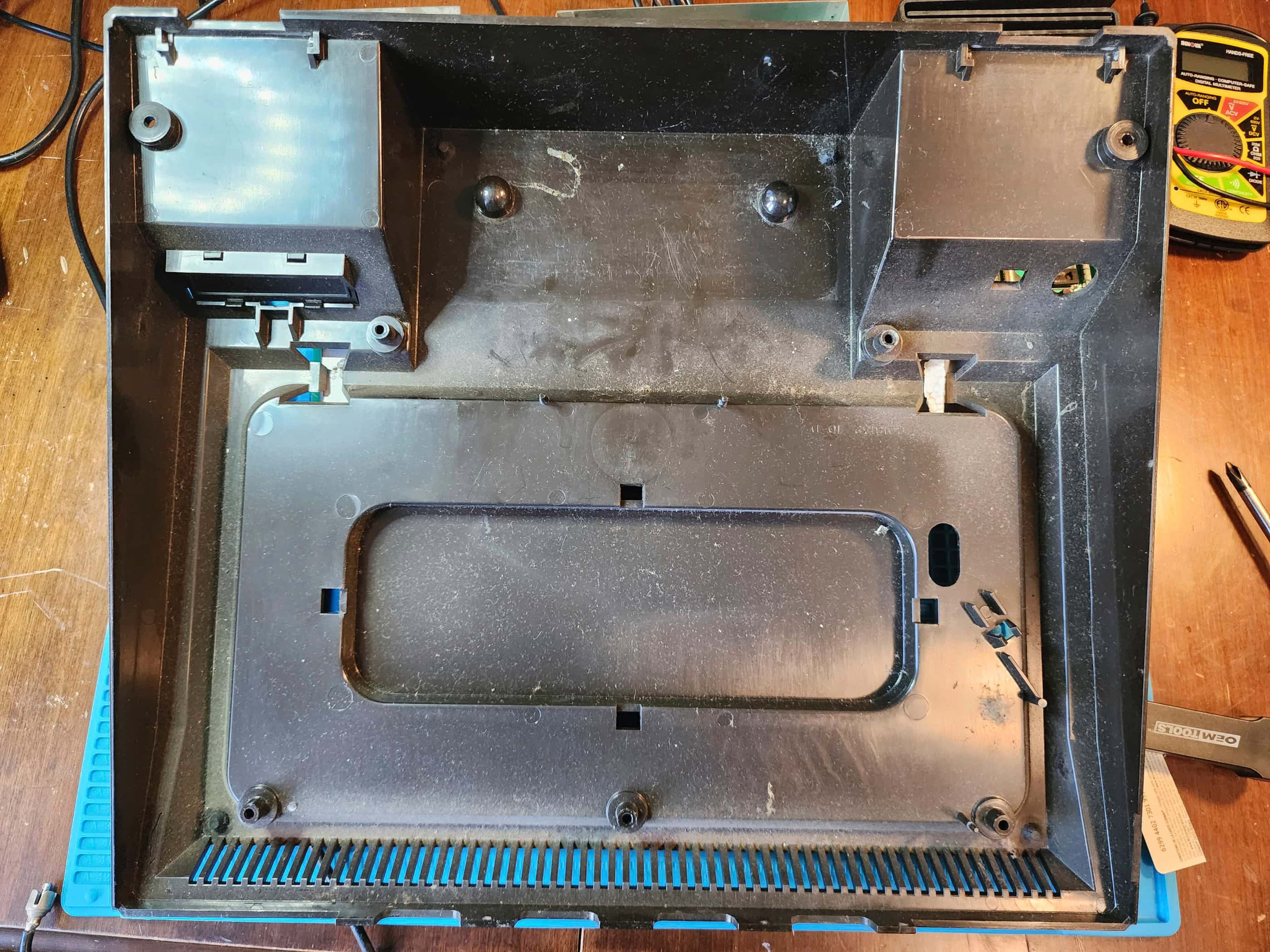
Atari 5200 Super System – 4 Port
Years (1982 – 1984)
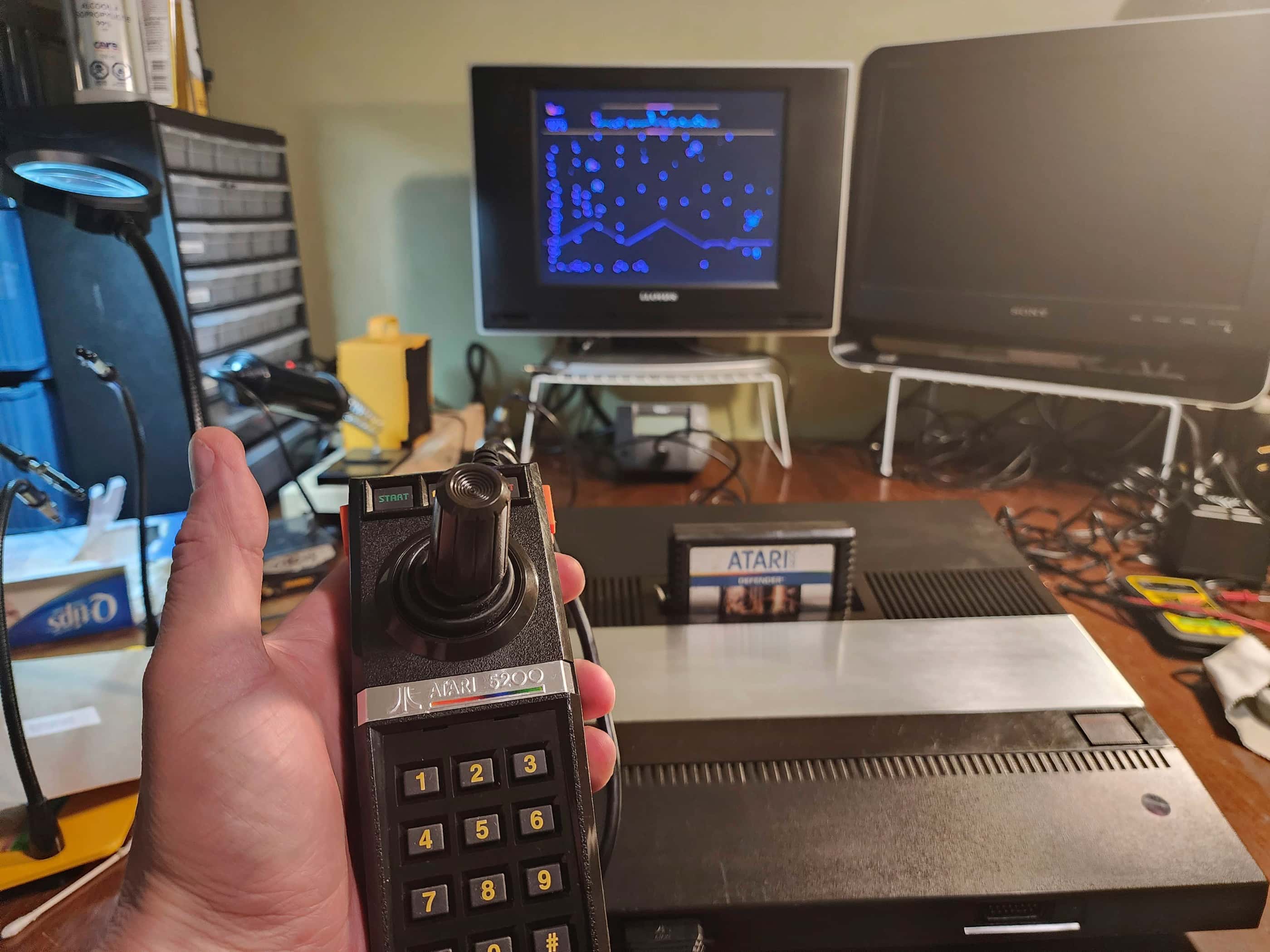
Interesting fact: The 5200 was launched to compete with Intellivision but soon found itself battling ColecoVision, which was also released in 1982. Built off Atari’s 8-bit computer platform (Atari 400 & 800), the 5200 was originally not backwards compatible with the 2600 (or any of the 8-bit computers) and this limited its acceptance. (source)
Condition When Acquired: Partially Functional – controllers did not work
Current Condition: Fully Functional


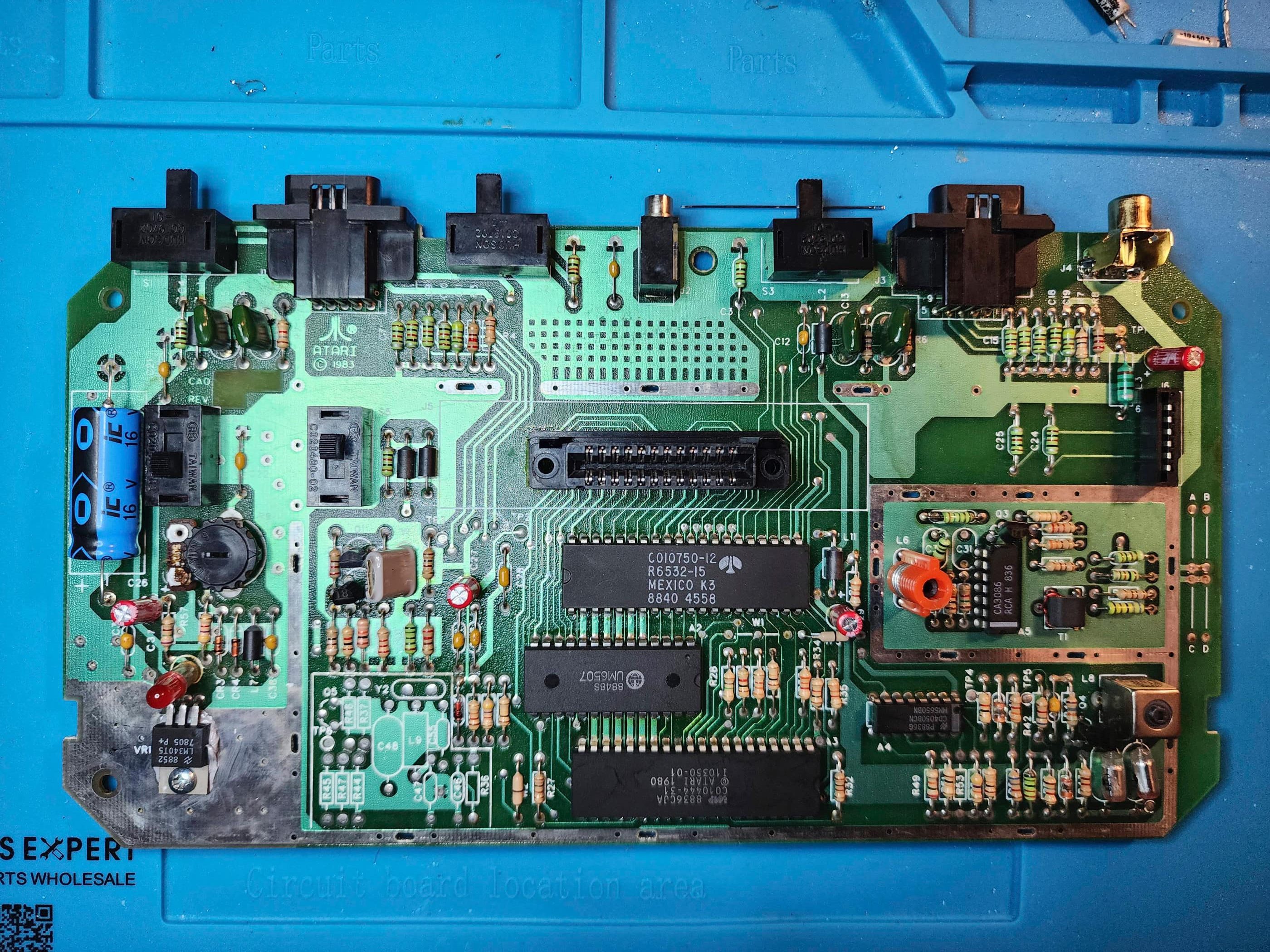
Project Details: This amazing system came from a collector’s estate and not only was the original box included, but the original packing foam and documentation as well! It also has a serial number that begins with an asterisk (*), which means that it was compatible with the Atari 2600 adapter that was sold separately. Previous versions of the 5200 had to be sent to an authorized repair shop to be modded to work with the adapter. Near the end of the 4 port production run, Atari began to do these mods in the factory and mark those ones with an asterisk in the serial number. According to AtariAge, the asterisk units are somewhat rare which makes this a cool find.
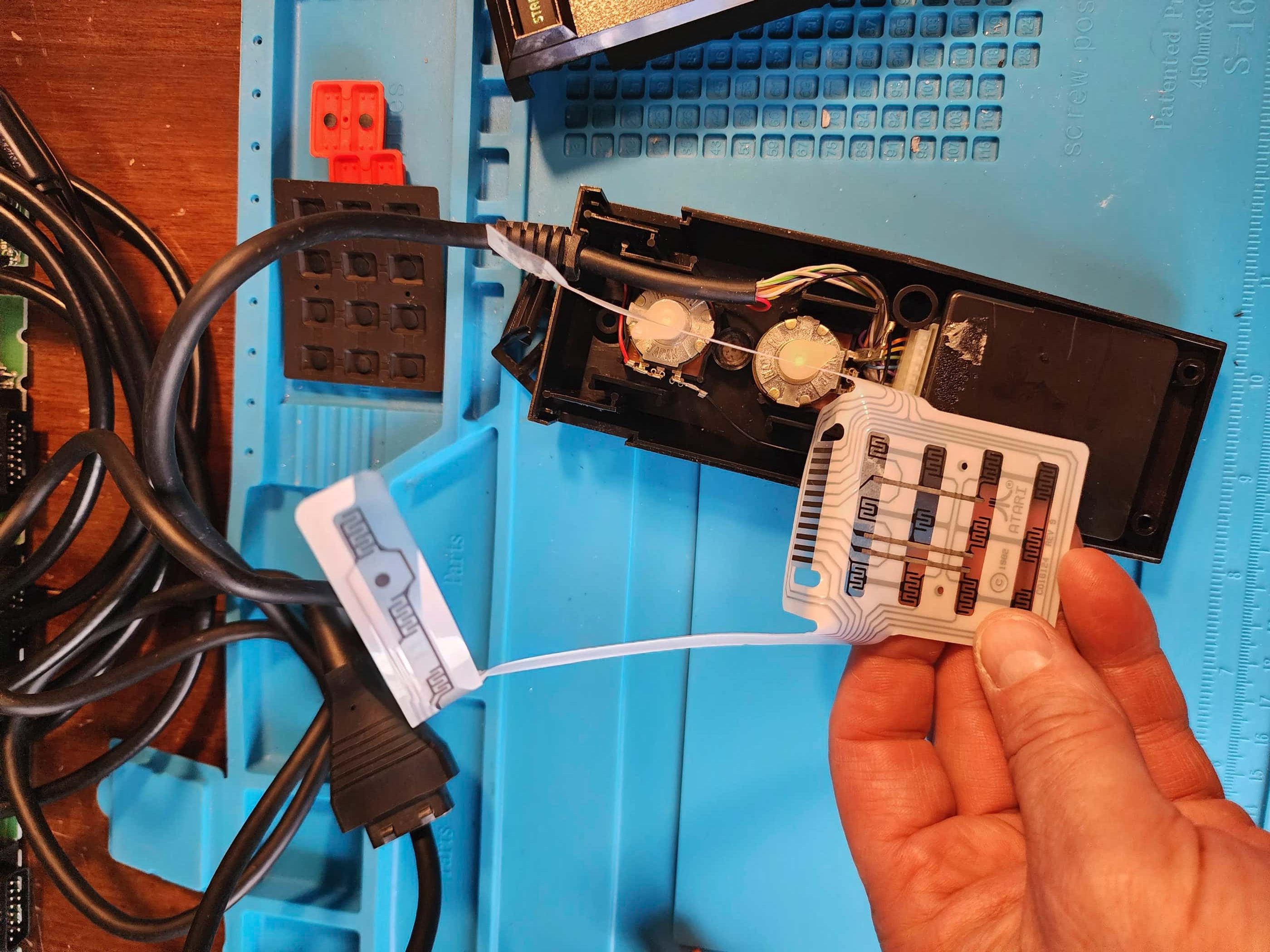
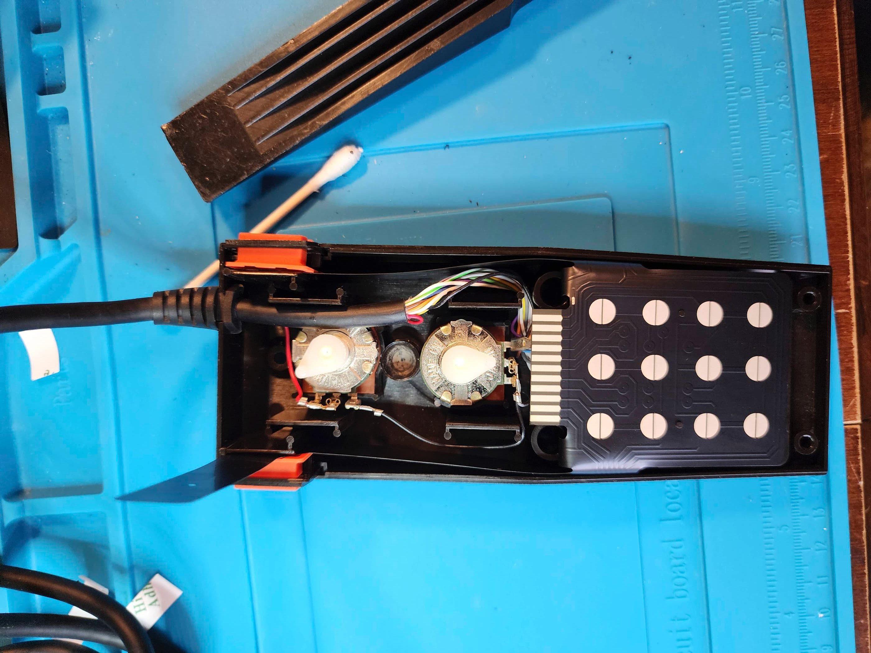
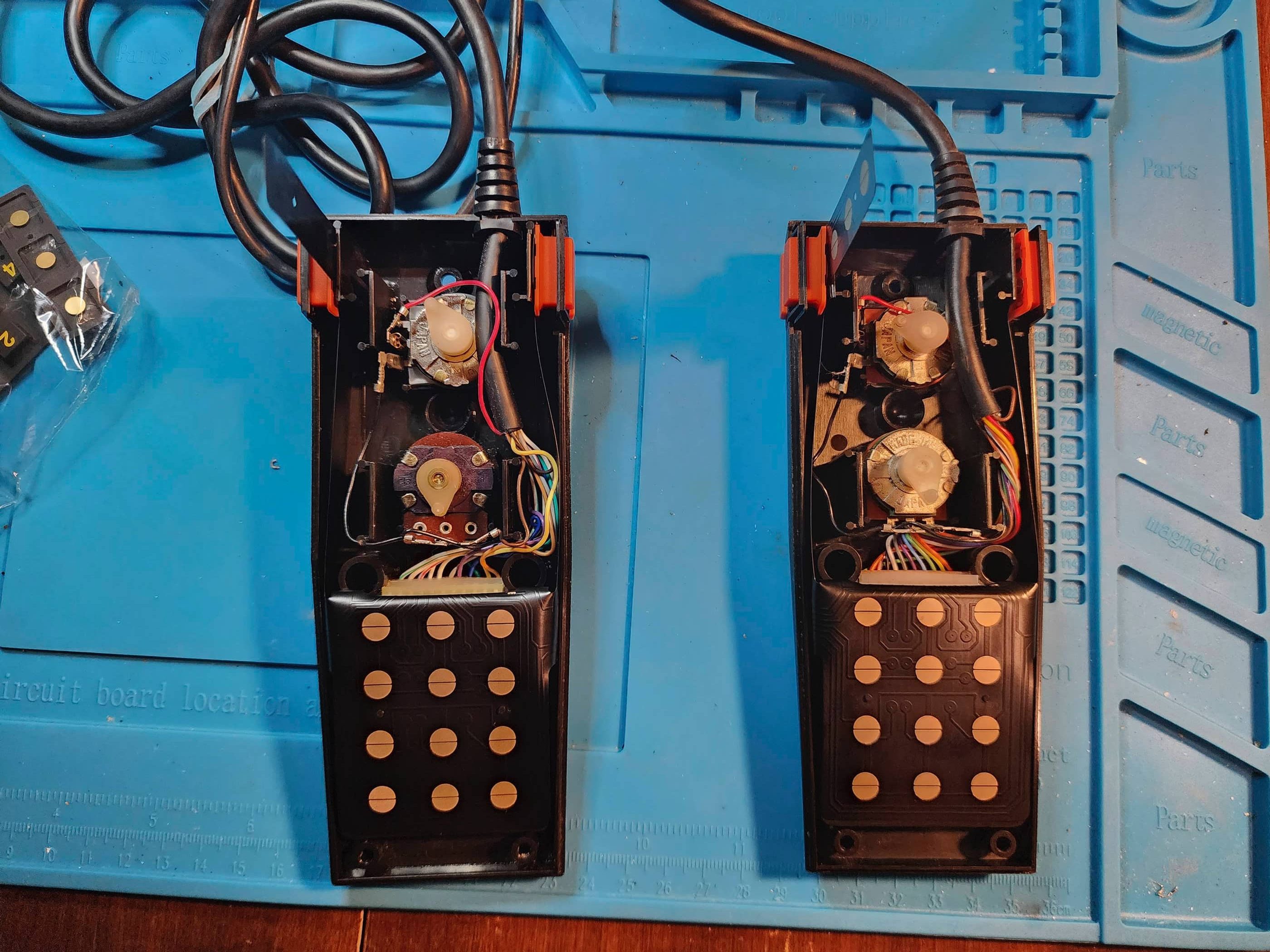
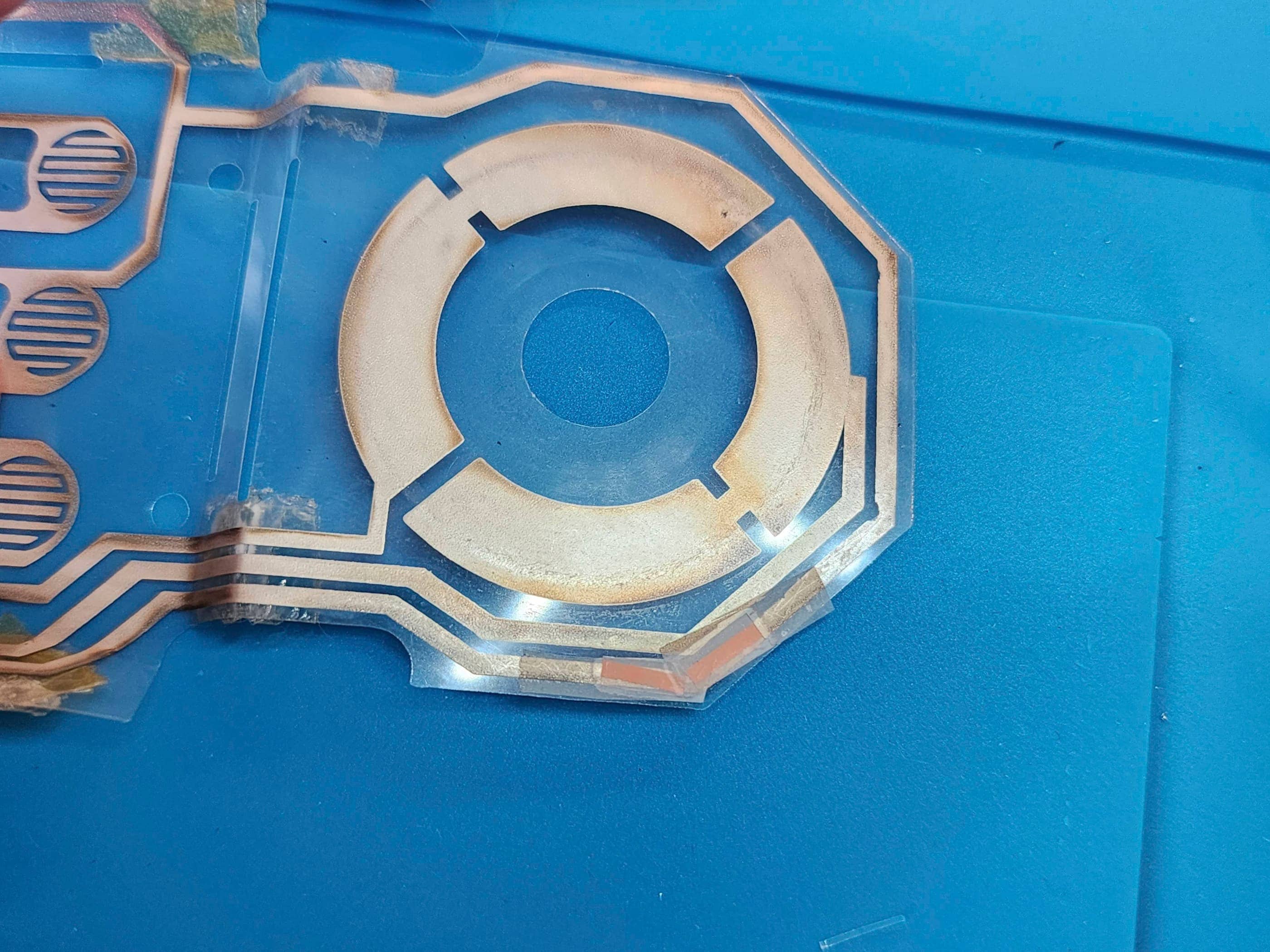
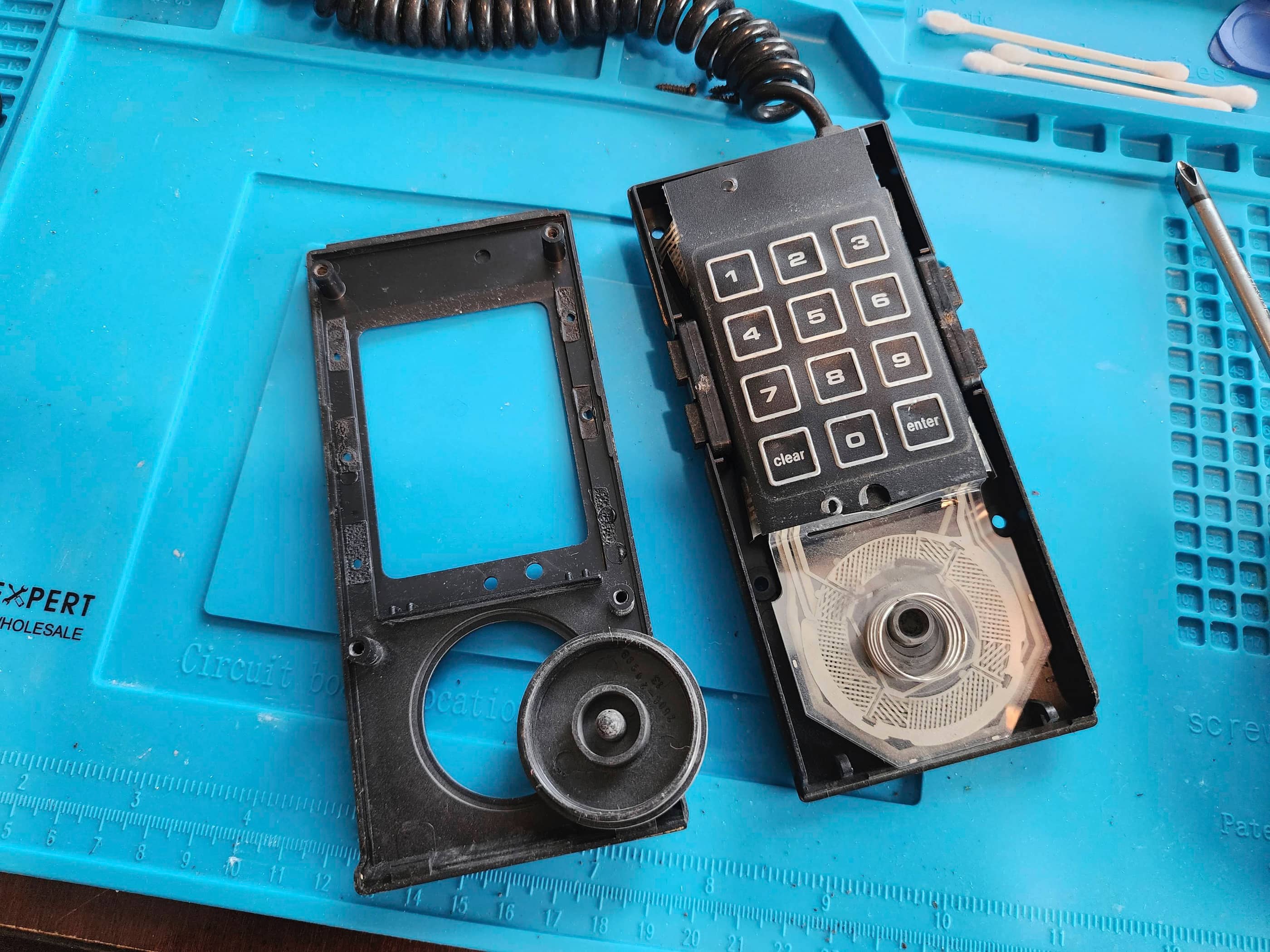
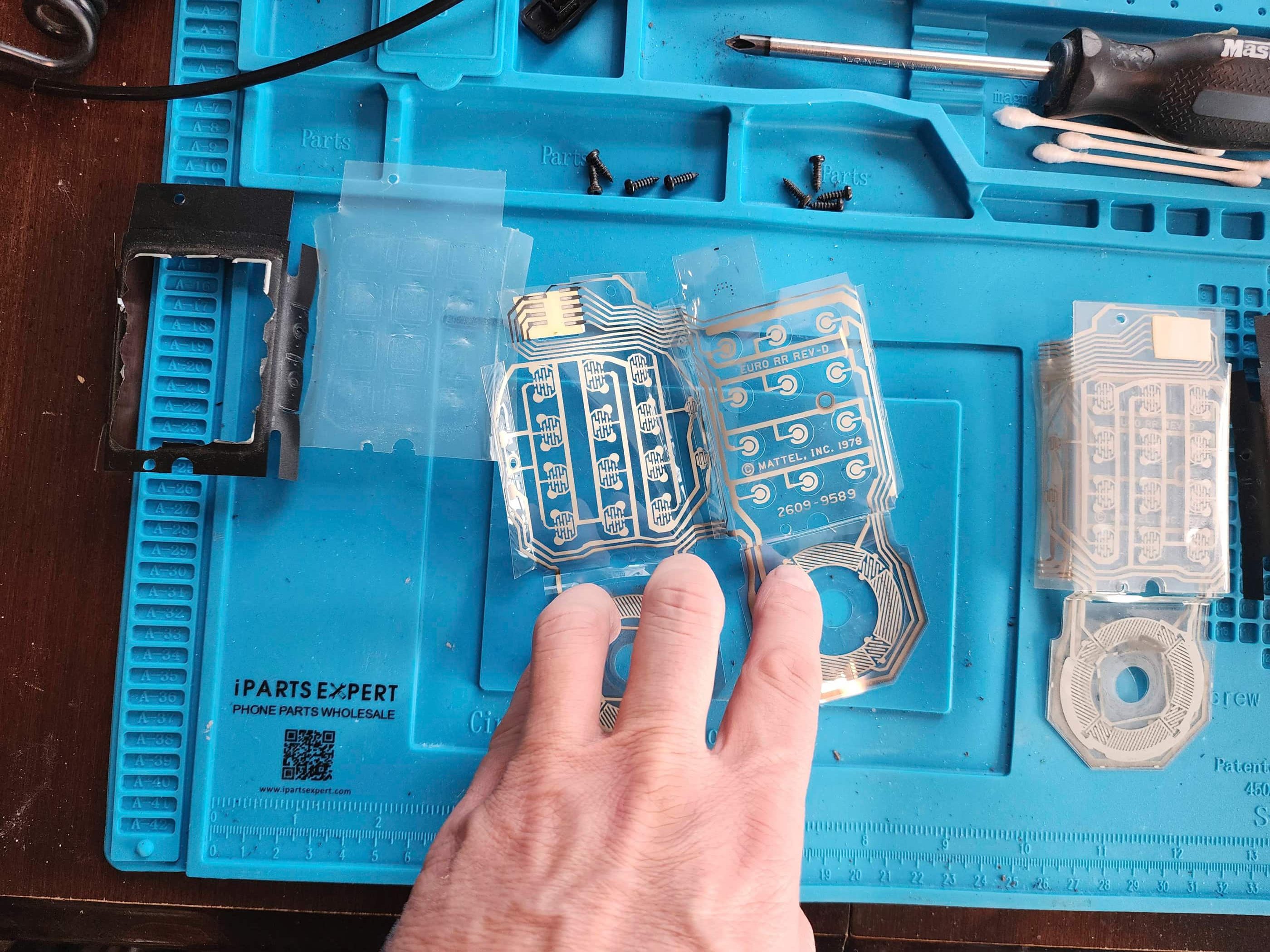
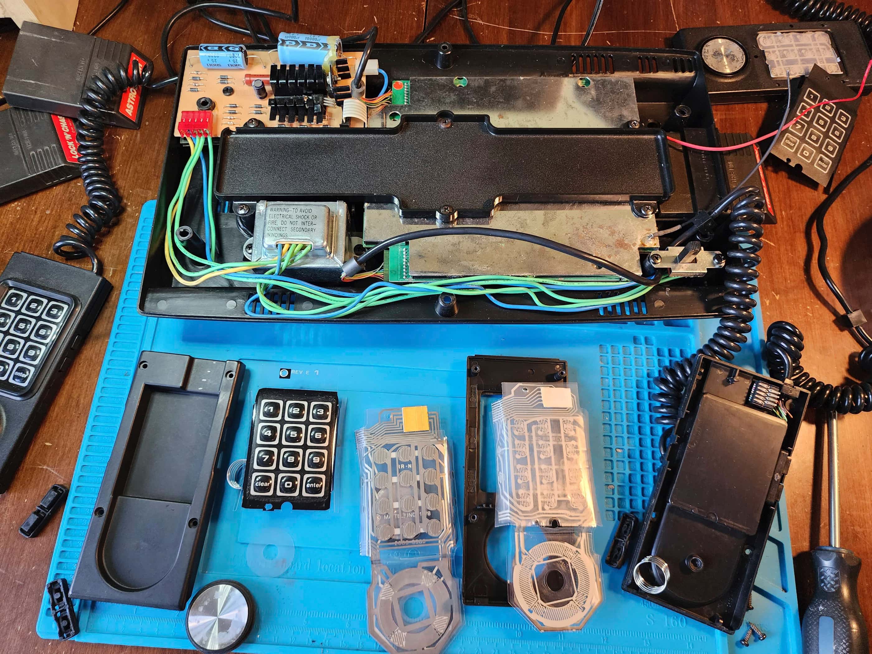
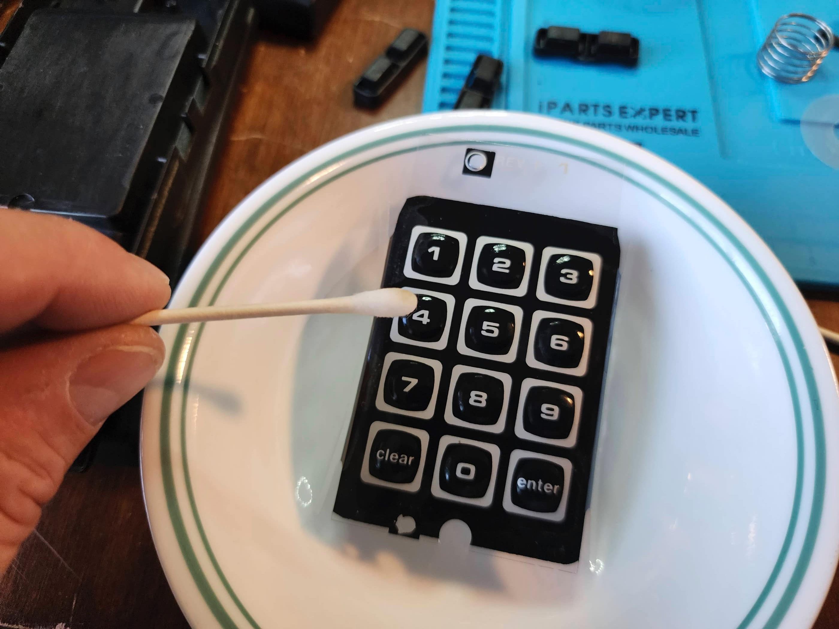
Anyway, back to the project… The system powered on without incident and Pac-Man looked and sounded like it was supposed to. The issue was, of the three included controllers, only one worked and it wasn’t great. This was a huge issue for these systems but fortunately there are companies that make new flex circuits and keypads that have improved on the original. So, instead of cleaning the flex circuits, I ordered a couple sets of rebuild kits from Atari Repair Parts. Once they arrived I took apart the system, cleaned it, and then reassembled it. Using the new parts, I then rebuilt two of the controllers (I kept the third one to be the second controller on my 2 port 5200). The result was two perfectly functioning controllers and a system that looks and runs like new. 🙂
Parts & Products Used: 99% isopropyl alcohol; Chemical Guys Natural Shine; Atari 5200 GOLD Full Controller Rebuild Kit;

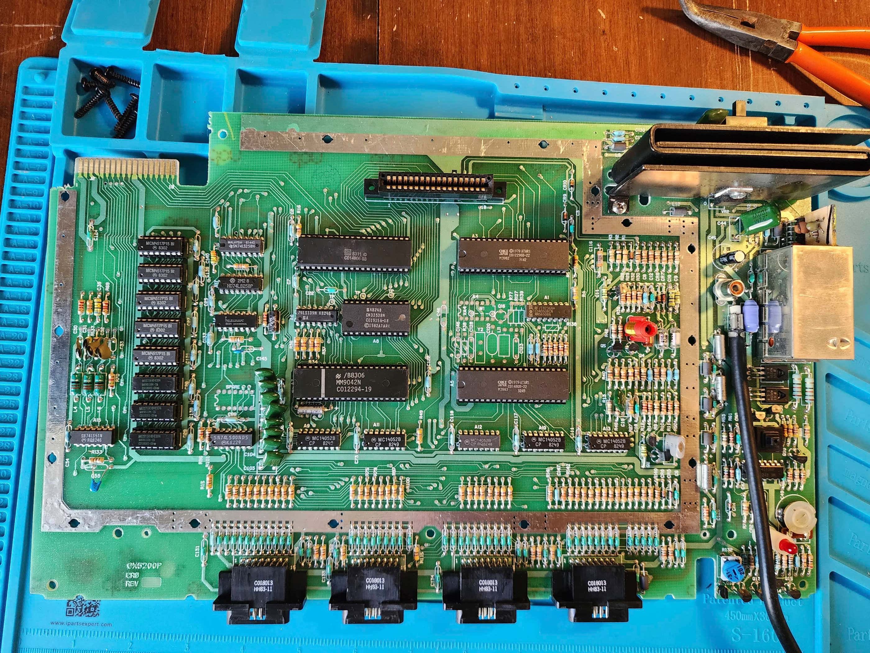
Atari 5200 Super System – 2 Port
Years (1982 – 1984)
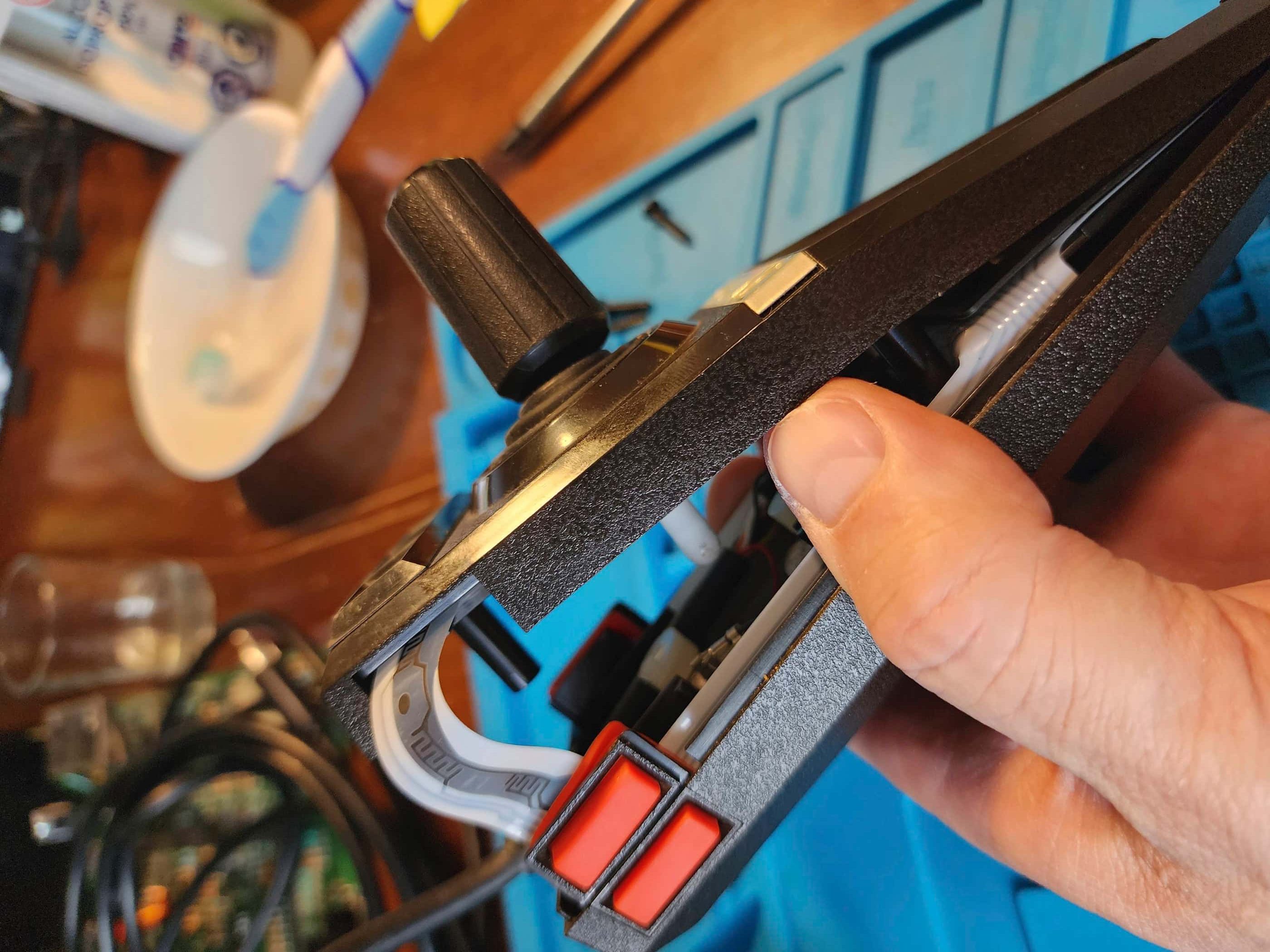
Interesting fact: The 5200 is sometimes said to have the worst controllers of any console. Its analog, non-centring joystick made precision movements difficult and it was subject to numerous quality control issues. It did however, pioneer the first dedicated ‘Pause’ button on a controller. (source)
Condition When Acquired: Partially Functional – power and controller issues
Current Condition: Fully Functional


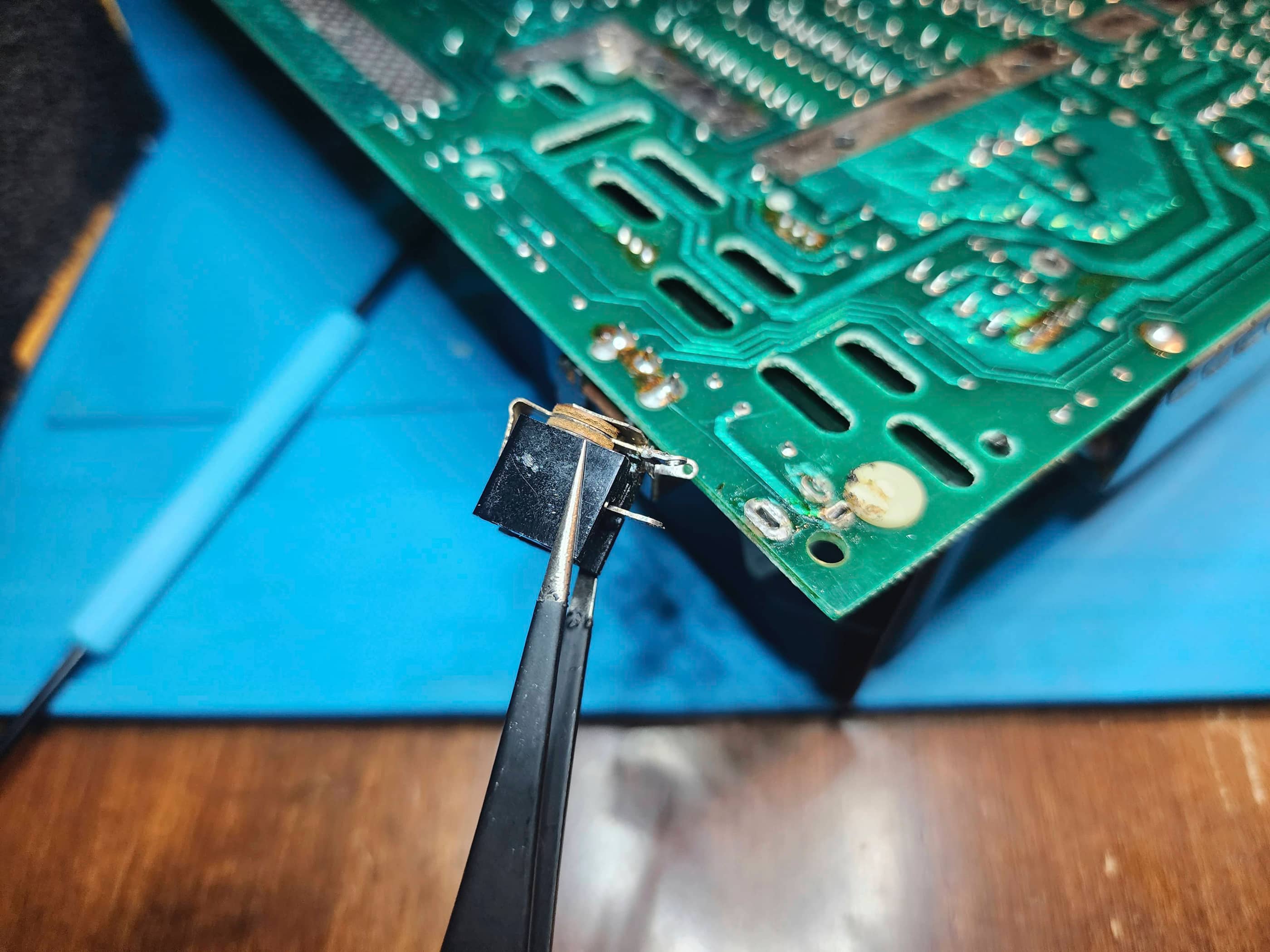

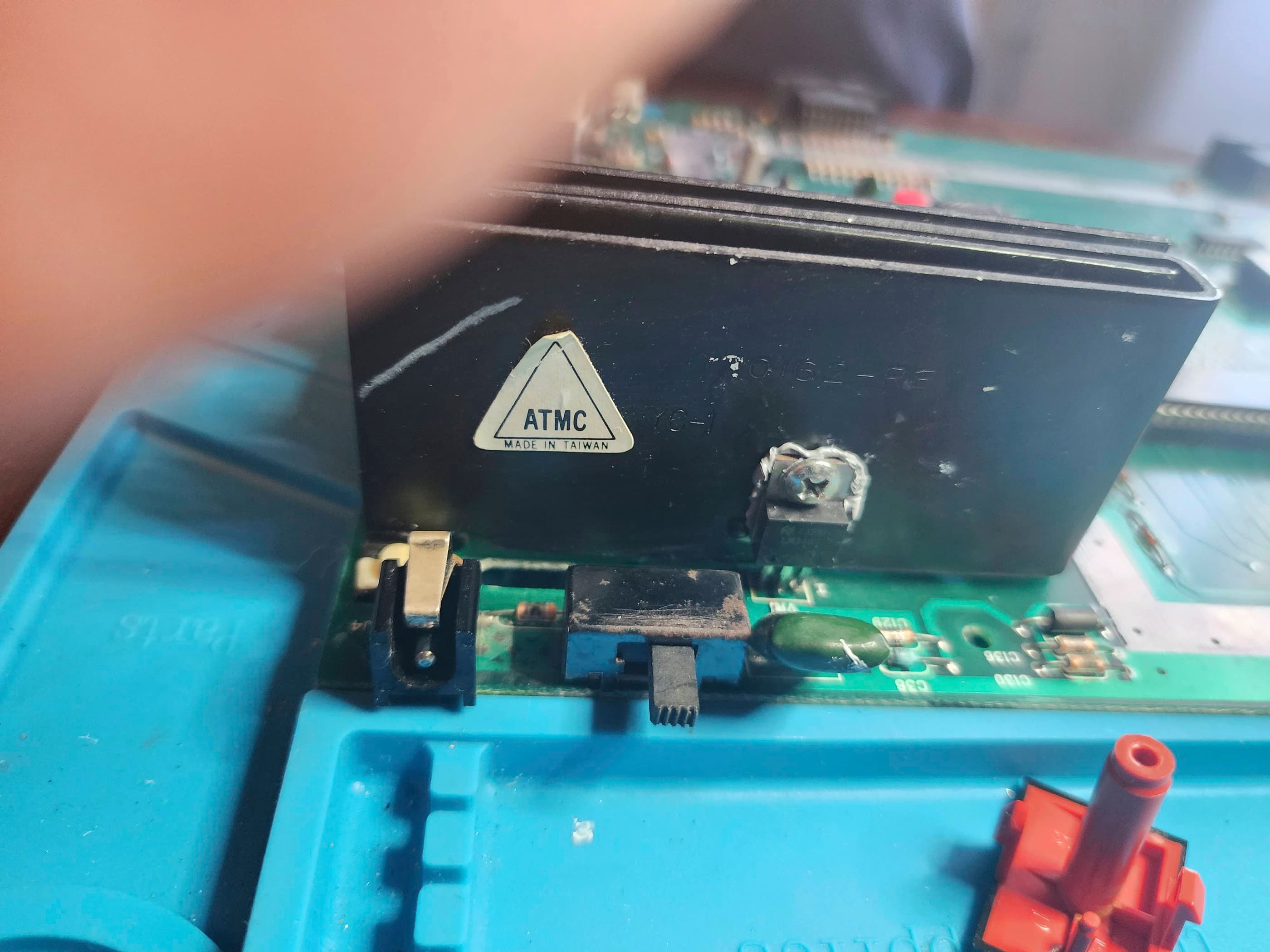
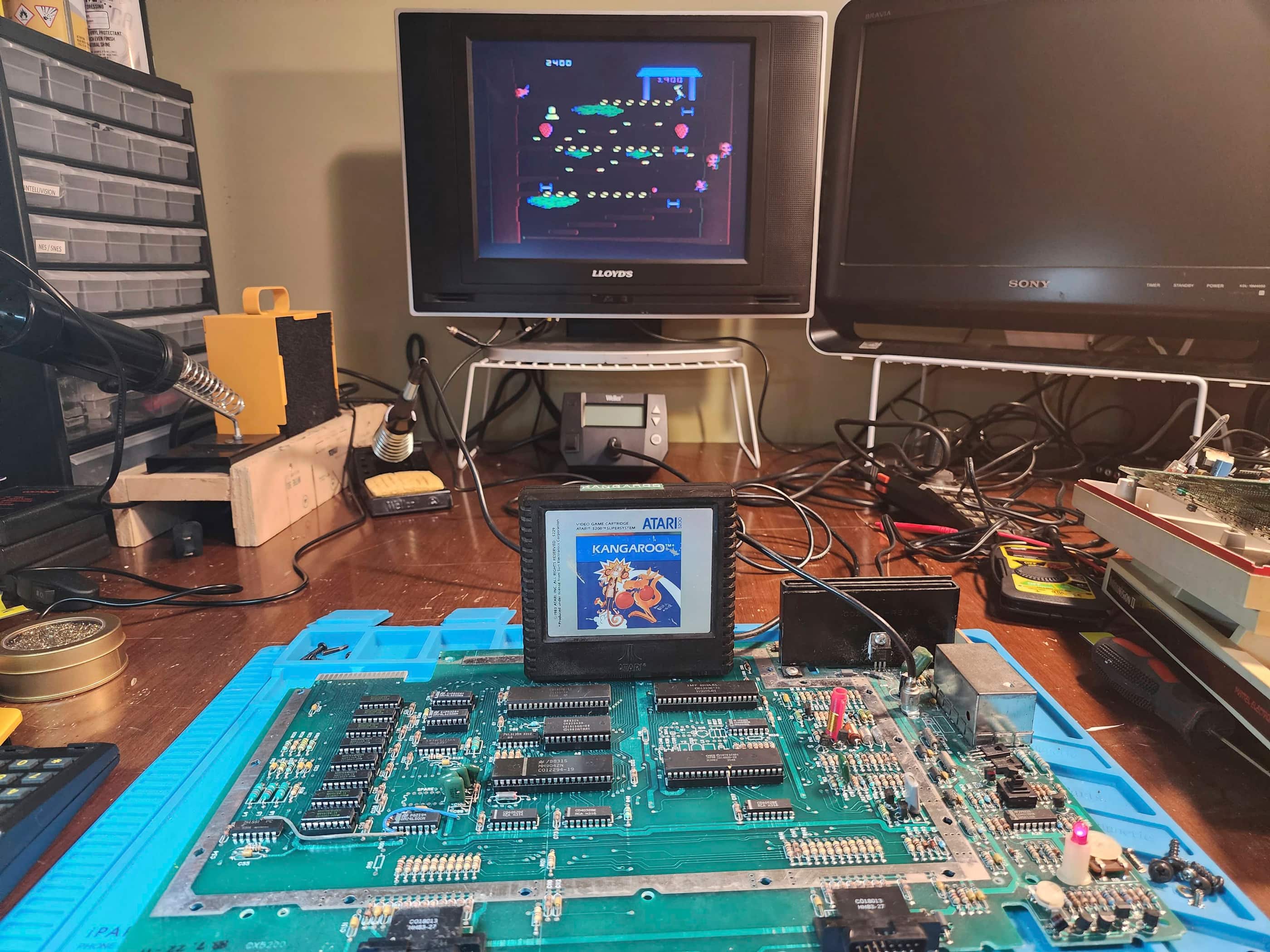


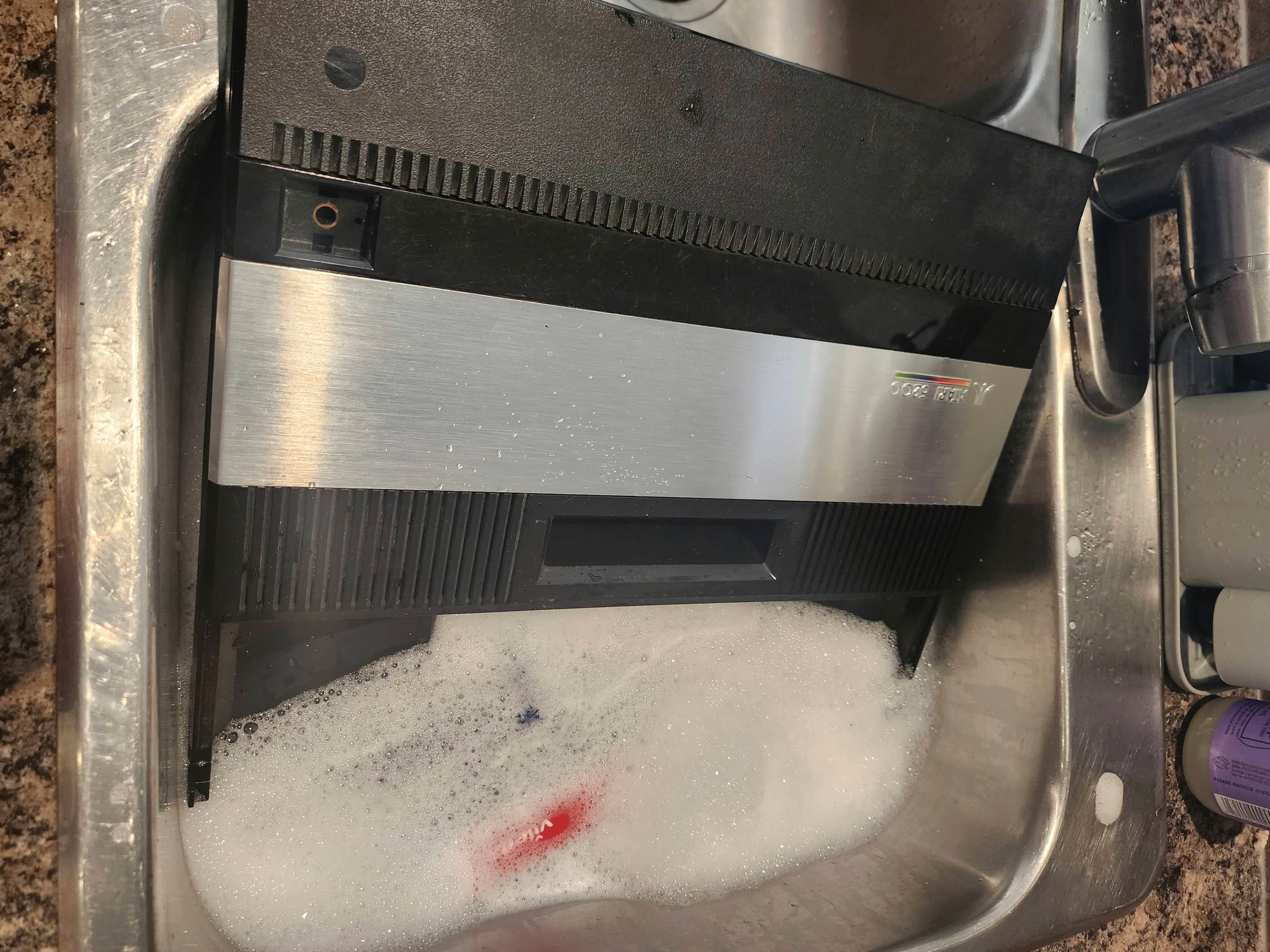

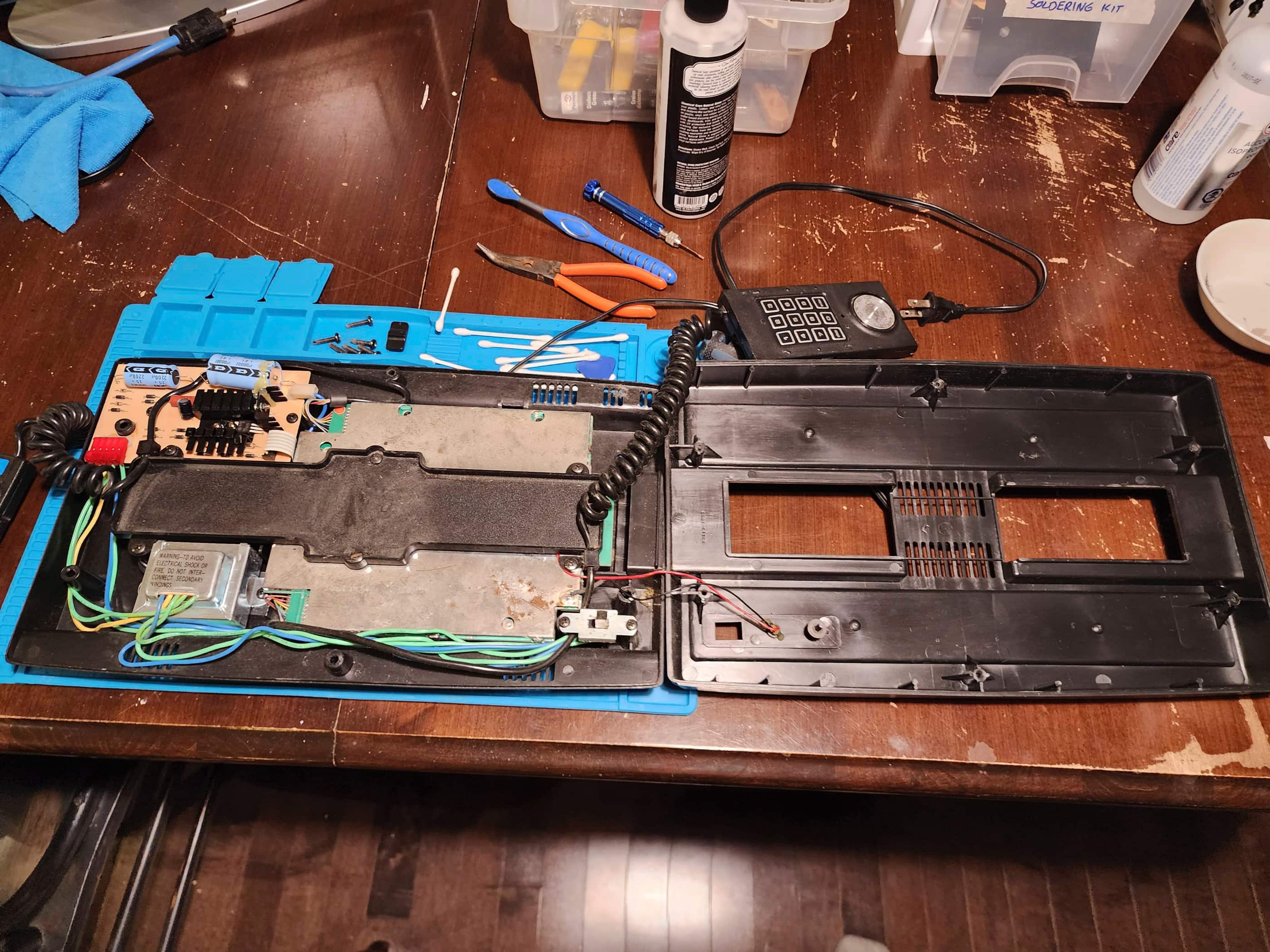
Project Details: I acquired this for a decent price and it came with one controller. The seller let me know that while the machine ‘should’ be functional, the controller had issues – quelle suprise for a 5200. When I received the unit, I tested the power supply and my multimeter initially showed 14.5v before jumping all over the map and then decreasing into the mv realm. Hmmm… 🤔 I plugged the unit in and it did not turn on. I tested the adapter again and it did the same thing. Finally, I got it to settle on a steady 14.5v. I’d never had this happen before, so speculated that the barrel of the adapter may be dirty. I cleaned it with IPA and again got it to a steady 14.5v. I plugged in the machine and presto! It powered on.
However, a couple more tests and it failed to turn on again, so I opened it up. It was extremely dusty inside and I could see the channel switch had rust on it. Next to it, I could see that the power jack was also badly corroded, which explained why the power was intermittent. Normally, I’d order a new jack, but the only ones I could find online that said they were for a 2 port 5200, had a contact pin on the opposite side, so these wouldn’t work. That’s when I got the idea to check the power jack on my Intellivision II (#3) as both systems have the same barrel size. It was an identical match and was in much better shape. Moreover, even though the INTY II input is VAC and the 5200 VDC, in theory it shouldn’t make a difference. So I desoldered the jacks from both boards and swapped them. I turned on the 5200 and it worked like it was supposed to. Several more power cycles proved that the original jack was the issue and that the INTY II jack had fixed the problem. 👍
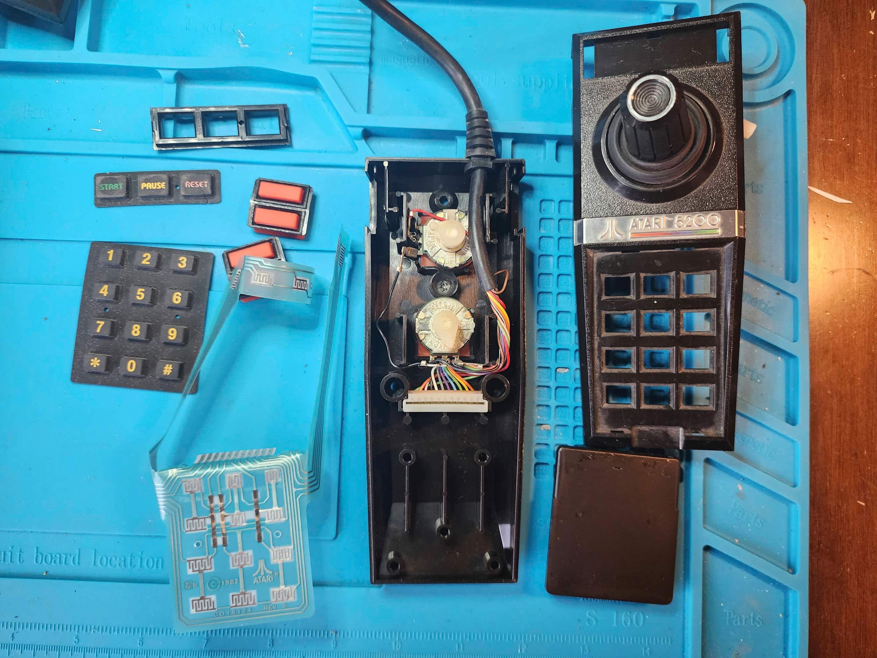
As for the controller, I was pleasantly surprised that it was in physically great shape. The rubber boot was intact and the keypad and buttons also looked good. I then tried the controller with a few games and it seemed to work okay, but the joystick seemed to have a bit too much play. Once my controller rebuild kit came from Atari Repair Parts, I took the controller apart and discovered that the plastic mechanism attached to the stick was very loose, which is why there was so much play. I swapped it for a new mechanism from a parts controller that engaged the potentiometers more firmly. I then added the new flex circuit, buttons, and keypads. I then rebuilt the controller that I’d moved over from my 4 port 5200. Finally, I spent a long time cleaning the entire system and applied new thermal paste to both of the 7805 voltage regulators. The console now works like it was meant to. 😊
Parts & Products Used: 99% isopropyl alcohol; Chemical Guys Natural Shine; Atari 5200 GOLD Full Controller Rebuild Kit; right angle replacement power jack salvaged from an Intellivision II; controller mechanism salvaged from a parts controller; thermal paste
Bally Computer System / Astrocade
Years (1978 – 1984)
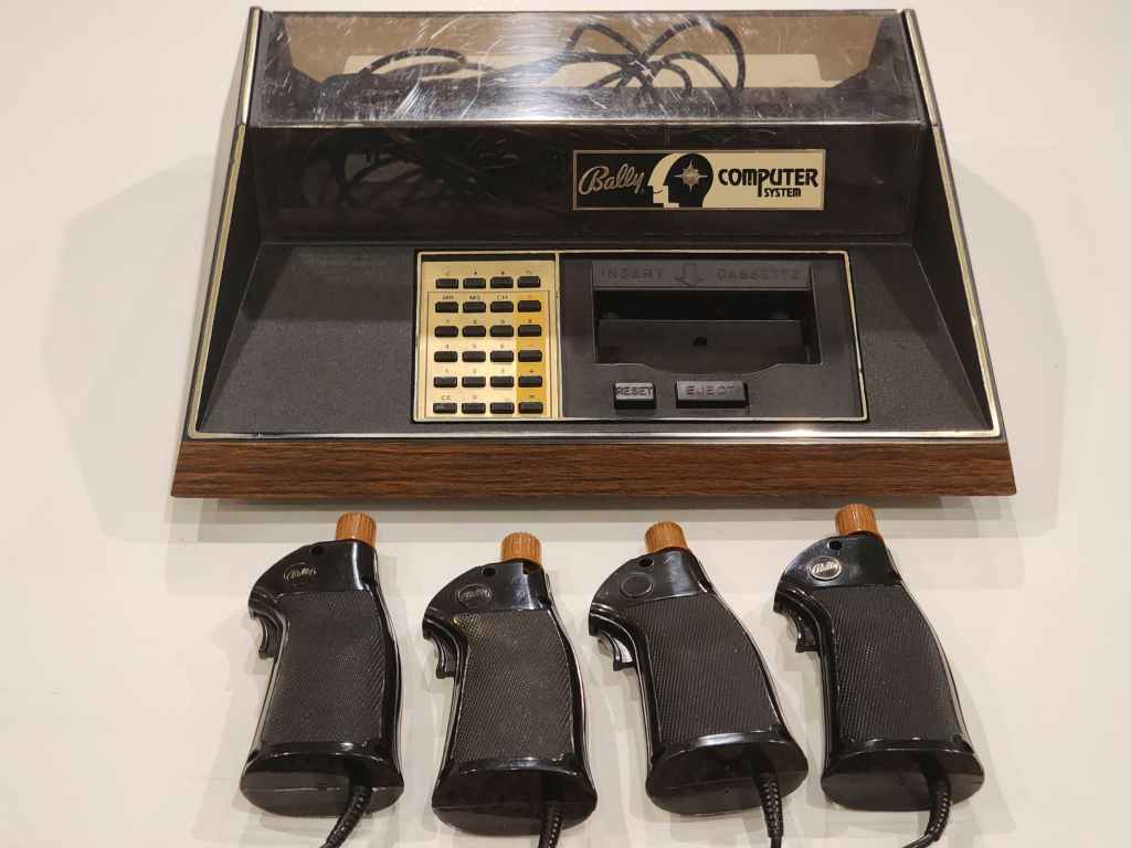
Interesting fact: Bally made its Home Library Computer to function as both a game console and a programmable BASIC computer. Unlike other cartridge systems of the era, Bally cartridges could be inserted after the unit had been turned on and the main menu displayed. It came with two built-in games and a drawing program and was originally only available through mail order. Bally renamed the console twice (Bally Professional Arcade – 1978 & Bally Computer System – 1980) before selling the console to Astrovision in 1980 who then changed the name to, Astrocade: The Professional Arcade. (source)
Condition When Acquired: Non-Functional (DOA)
Current Condition: Fully Functional


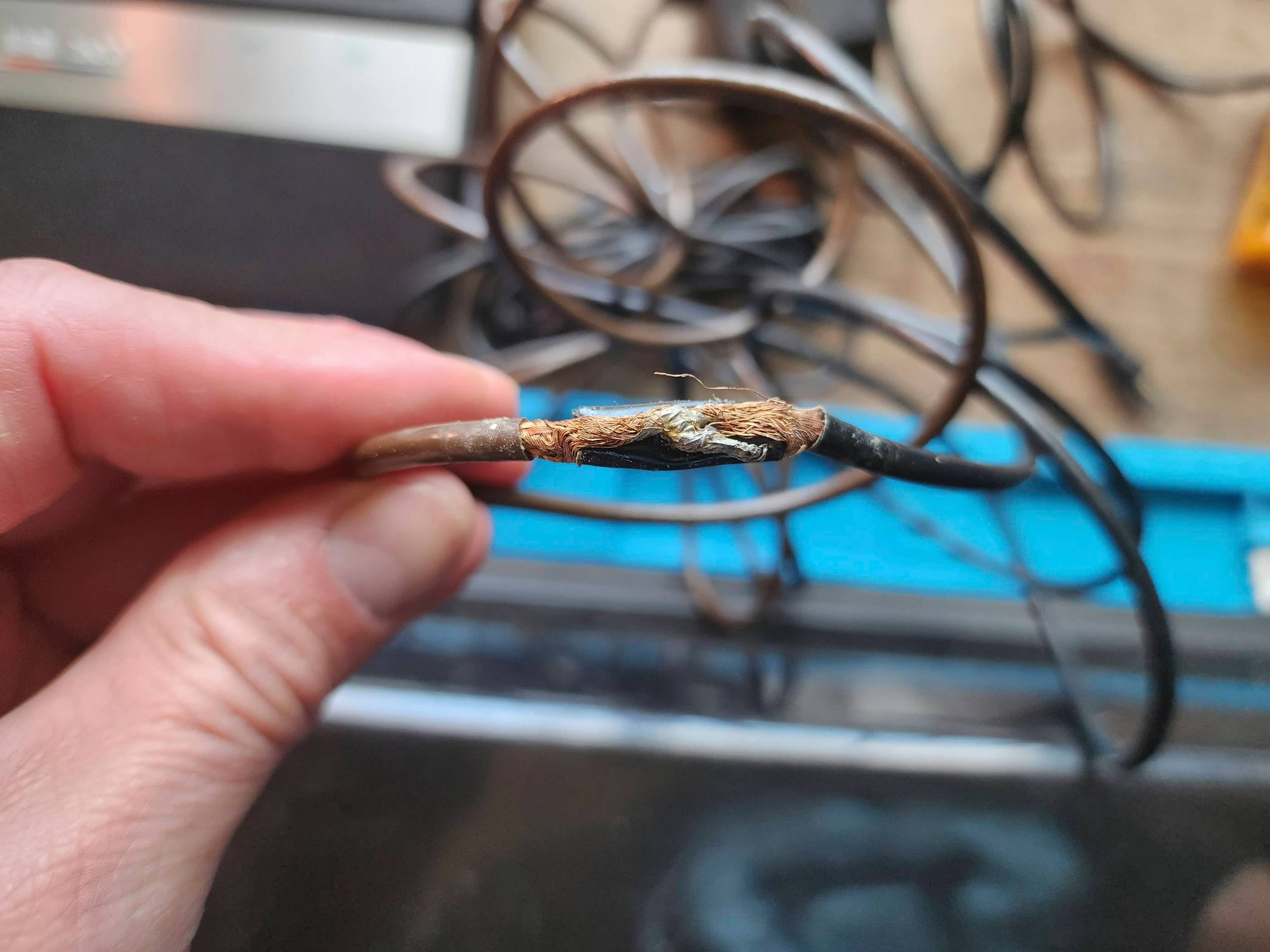


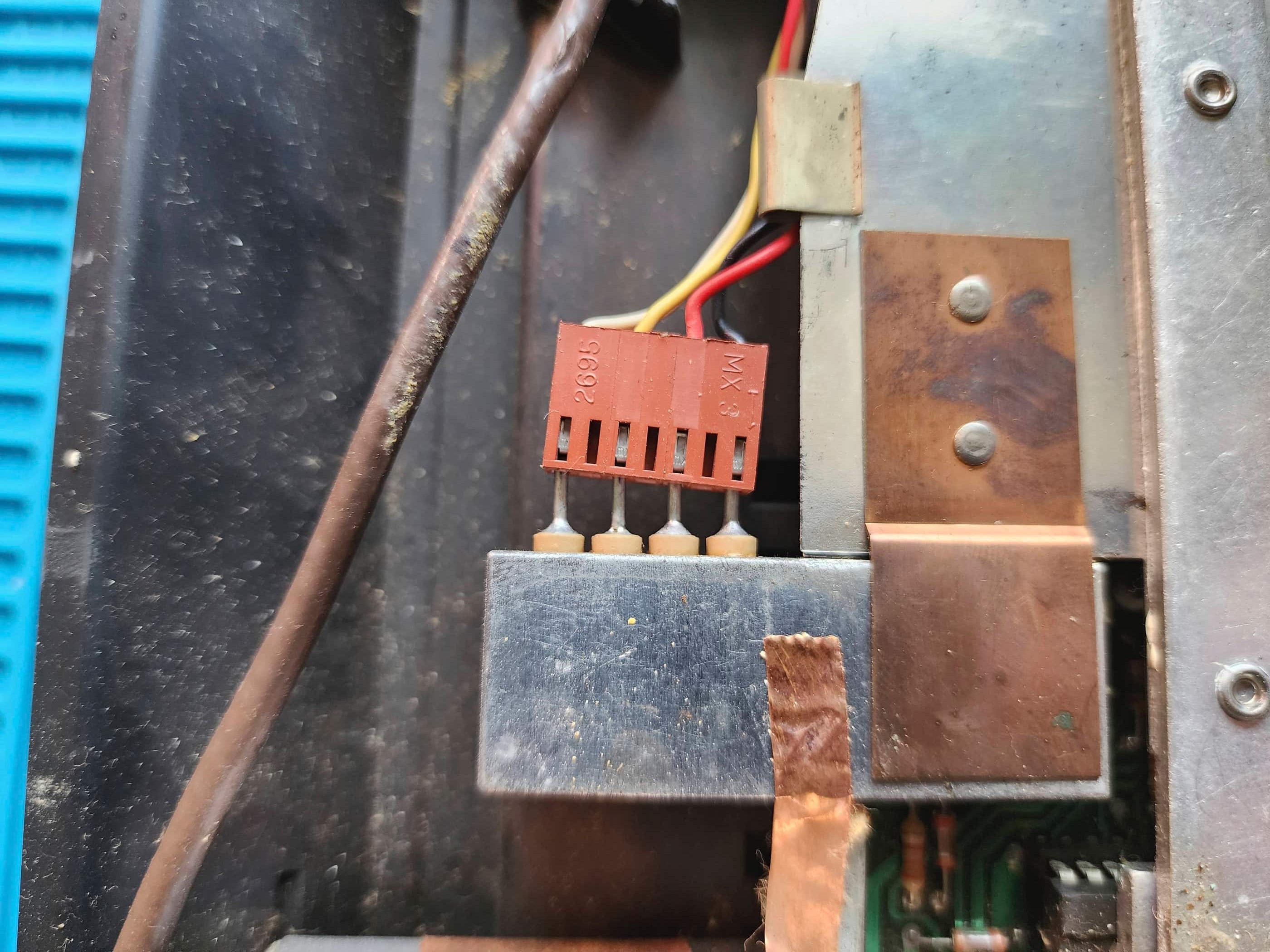
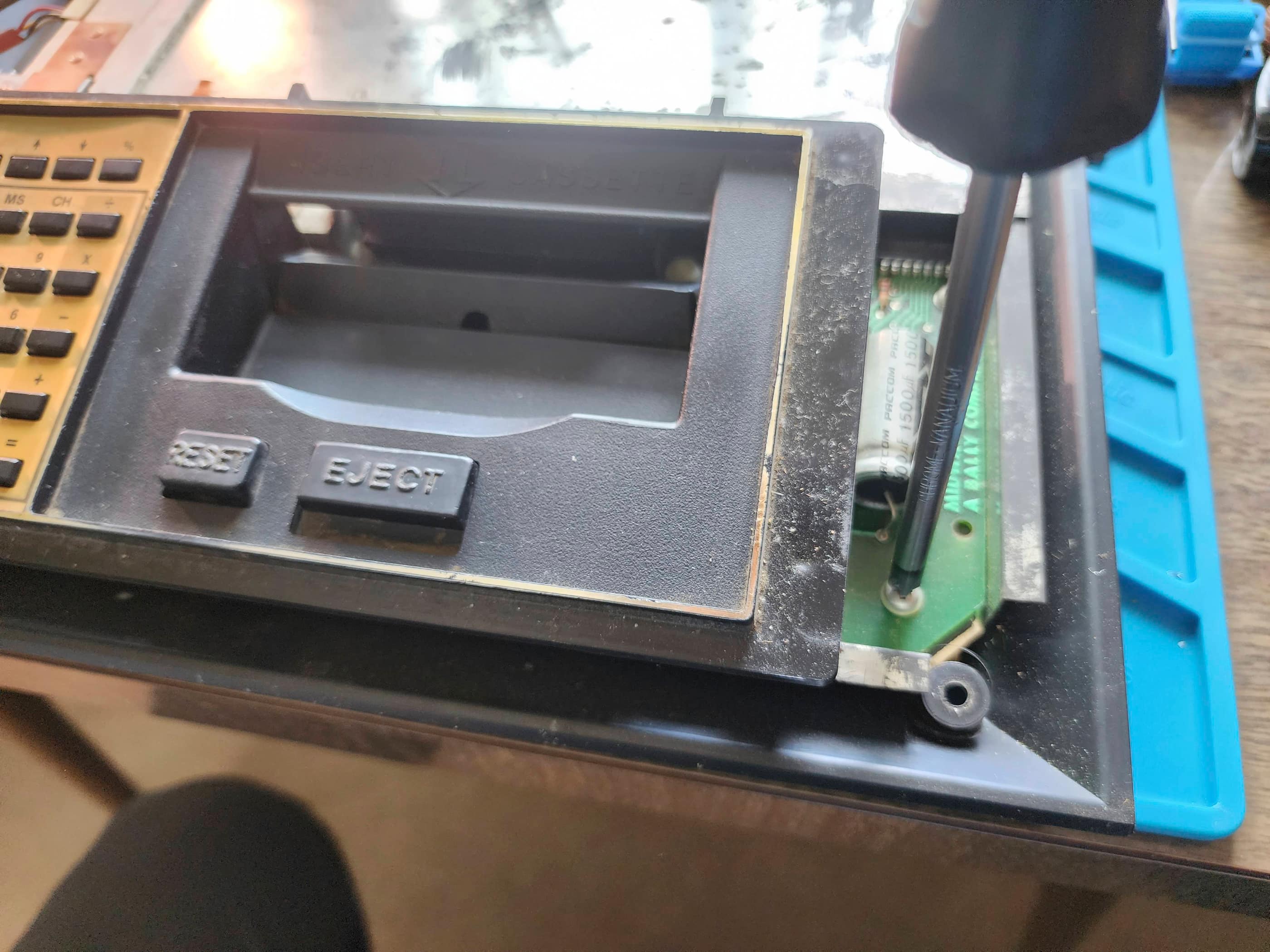
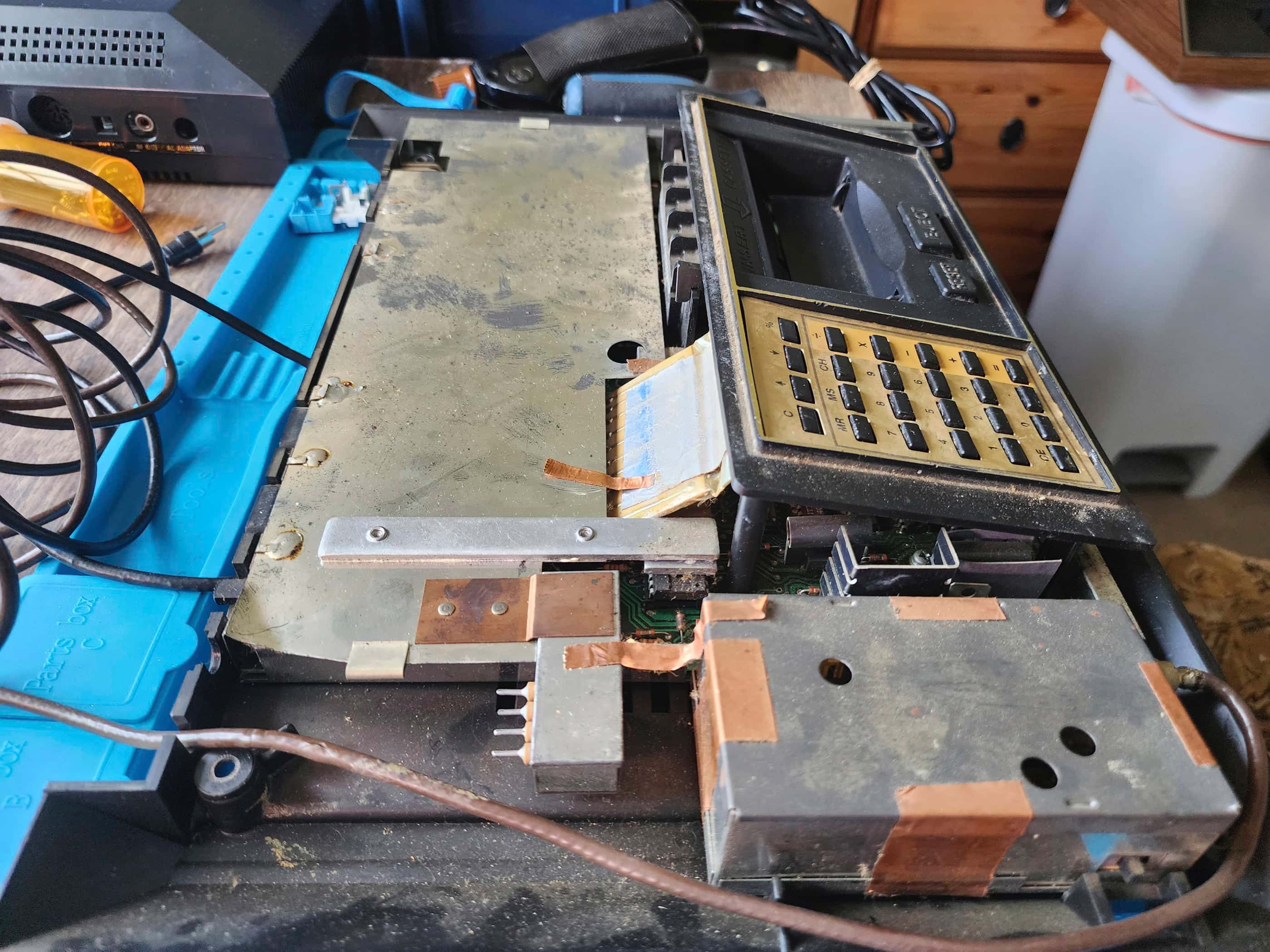
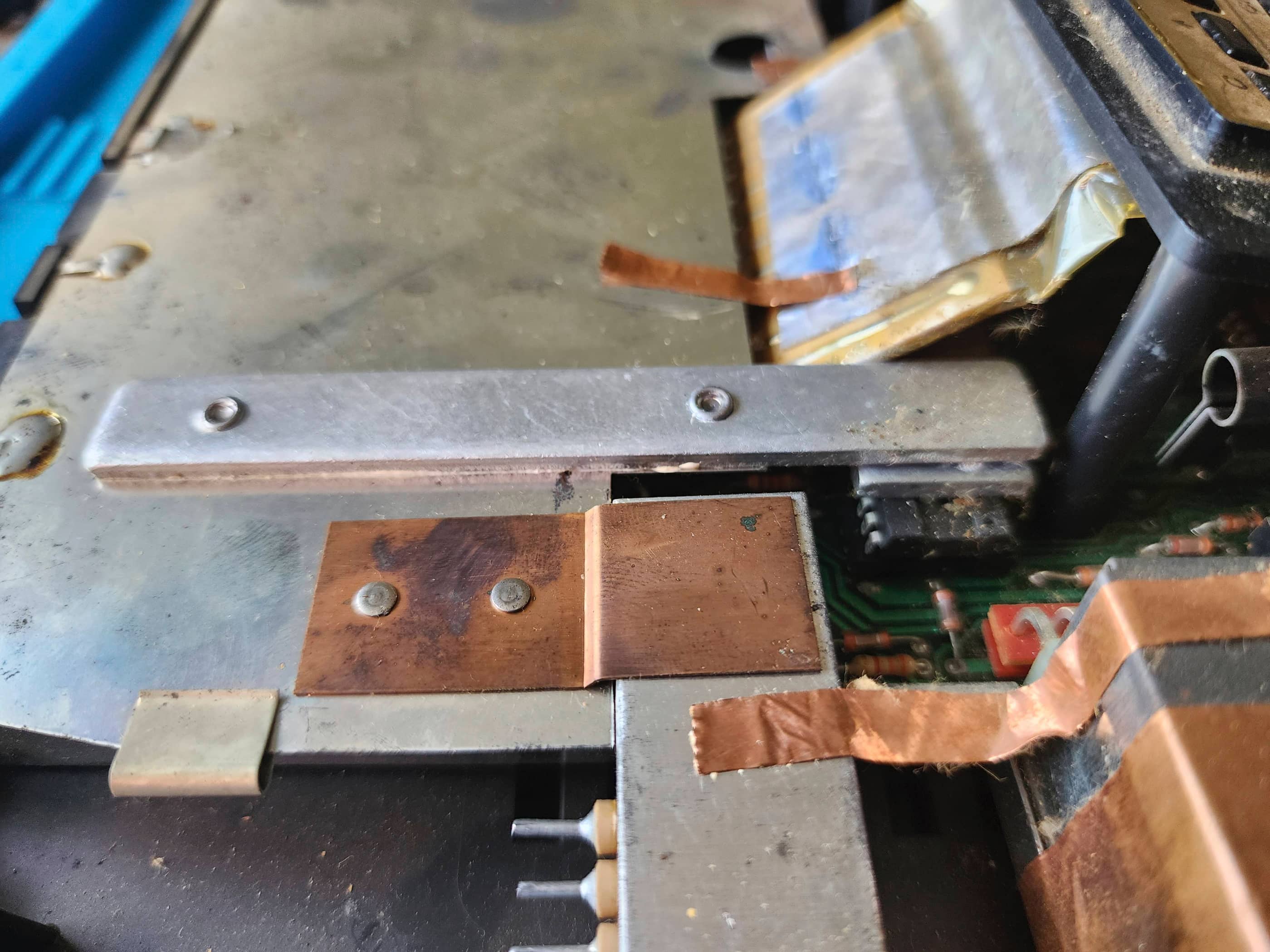


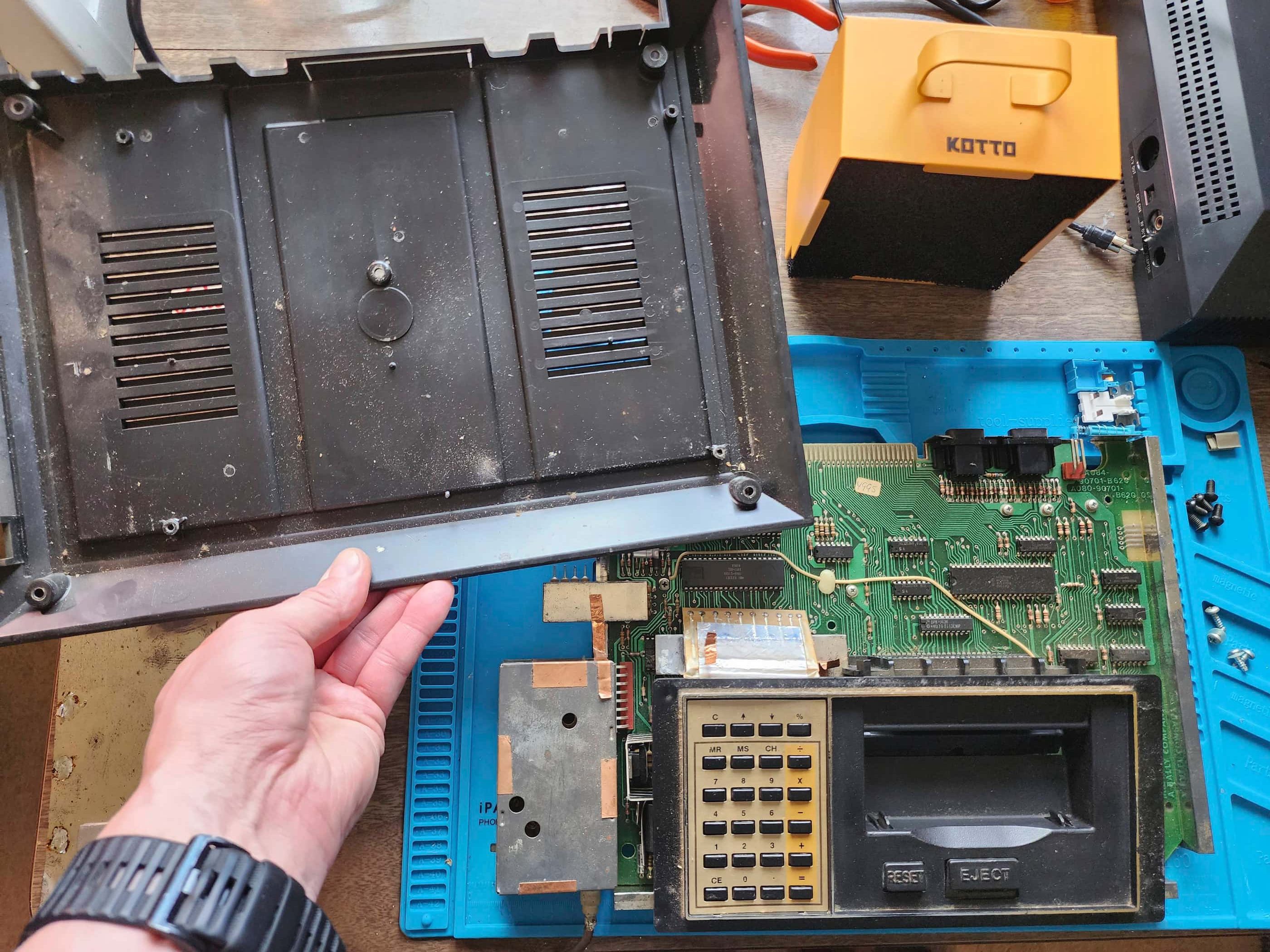
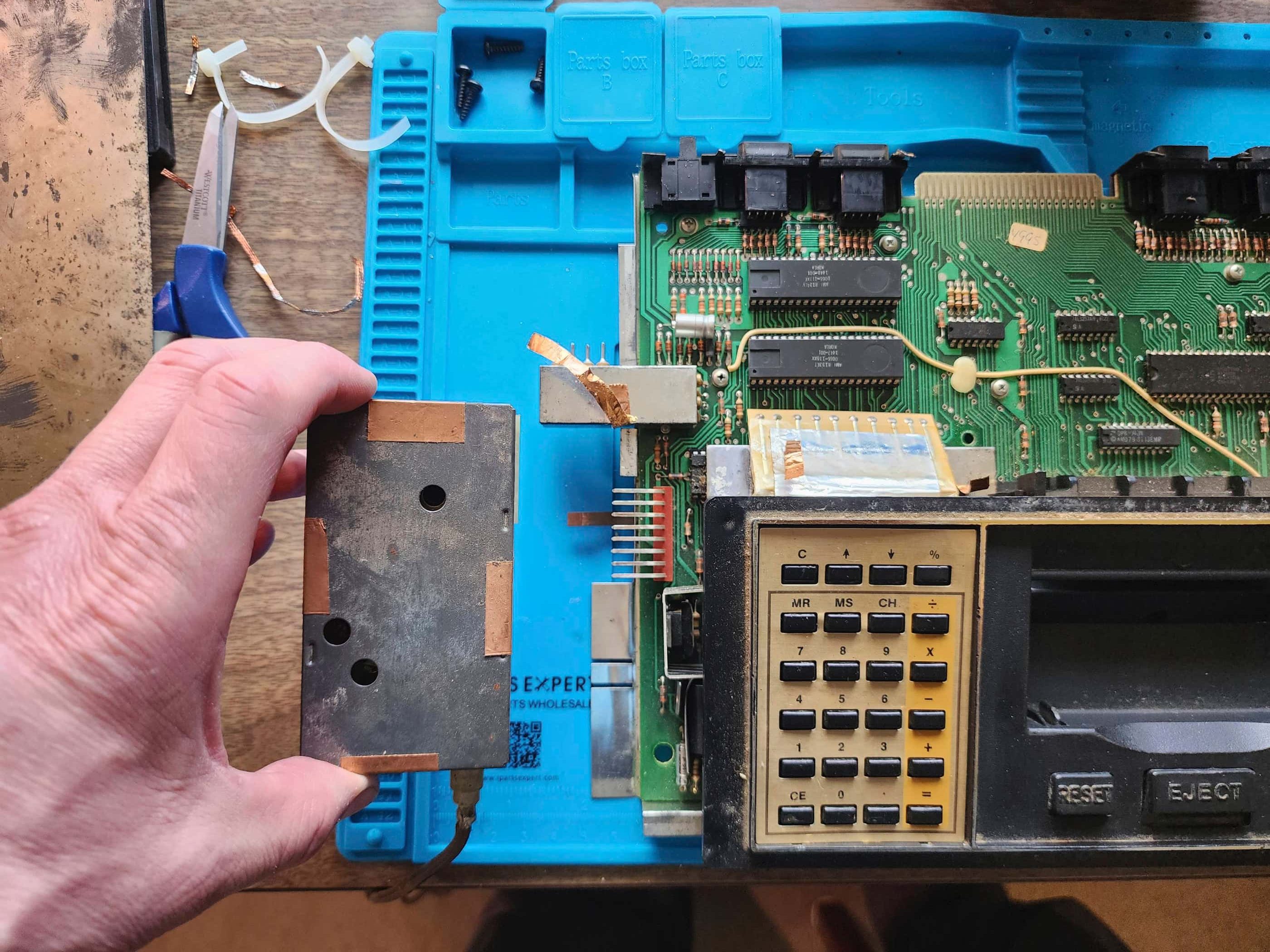
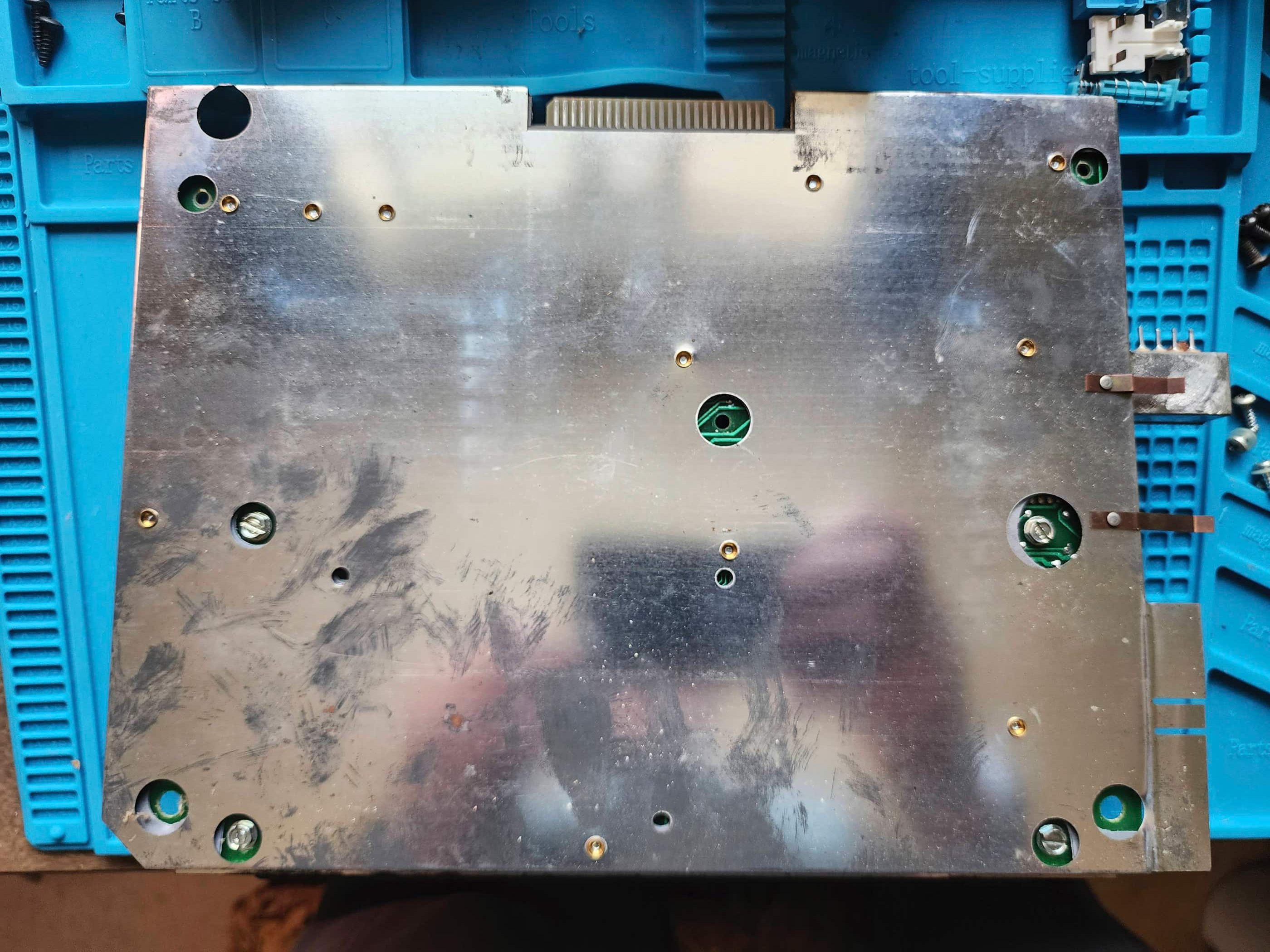
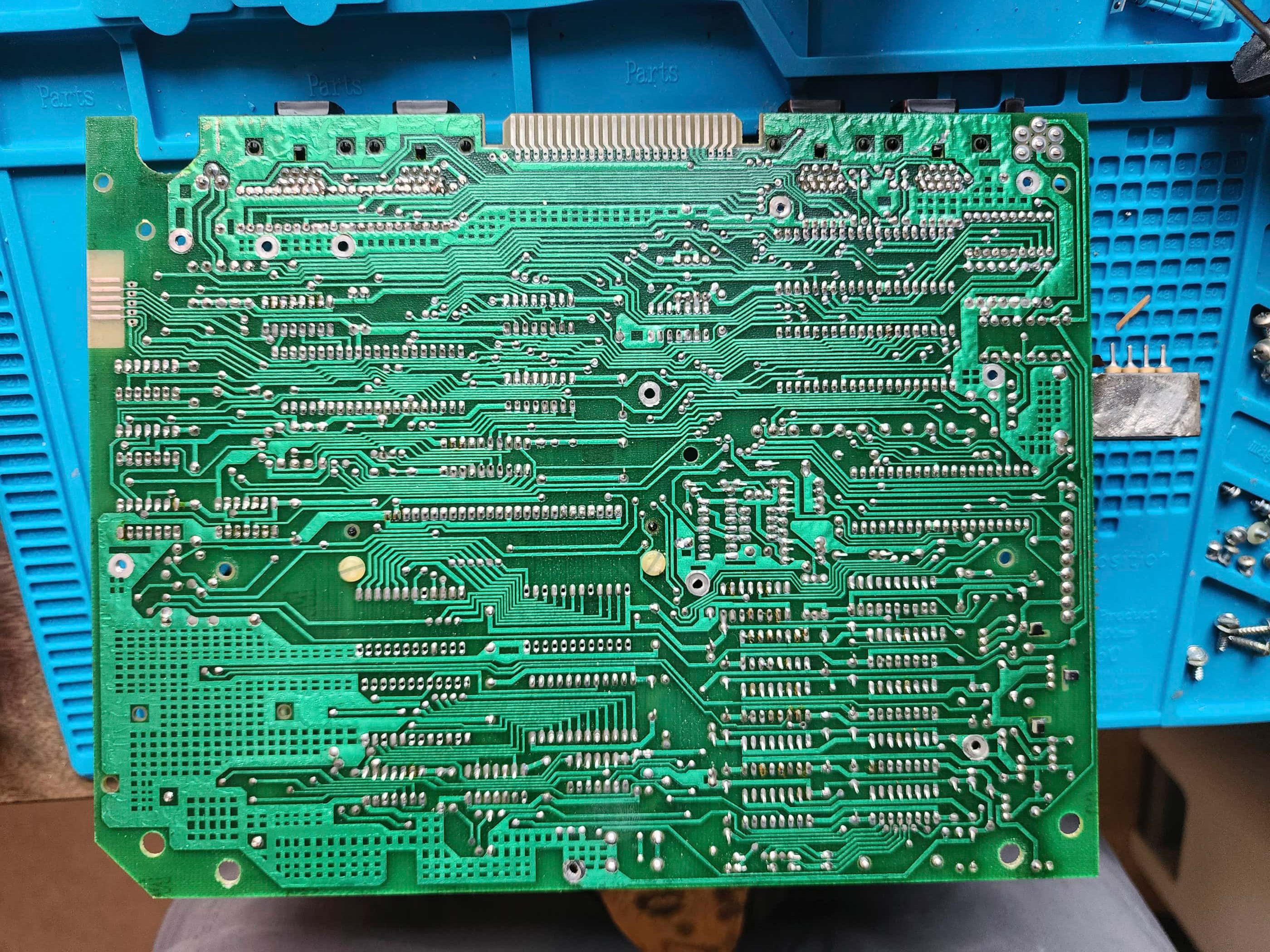
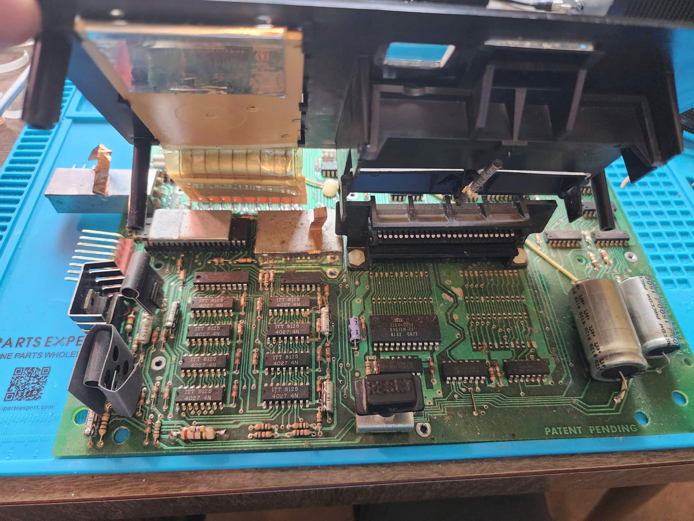


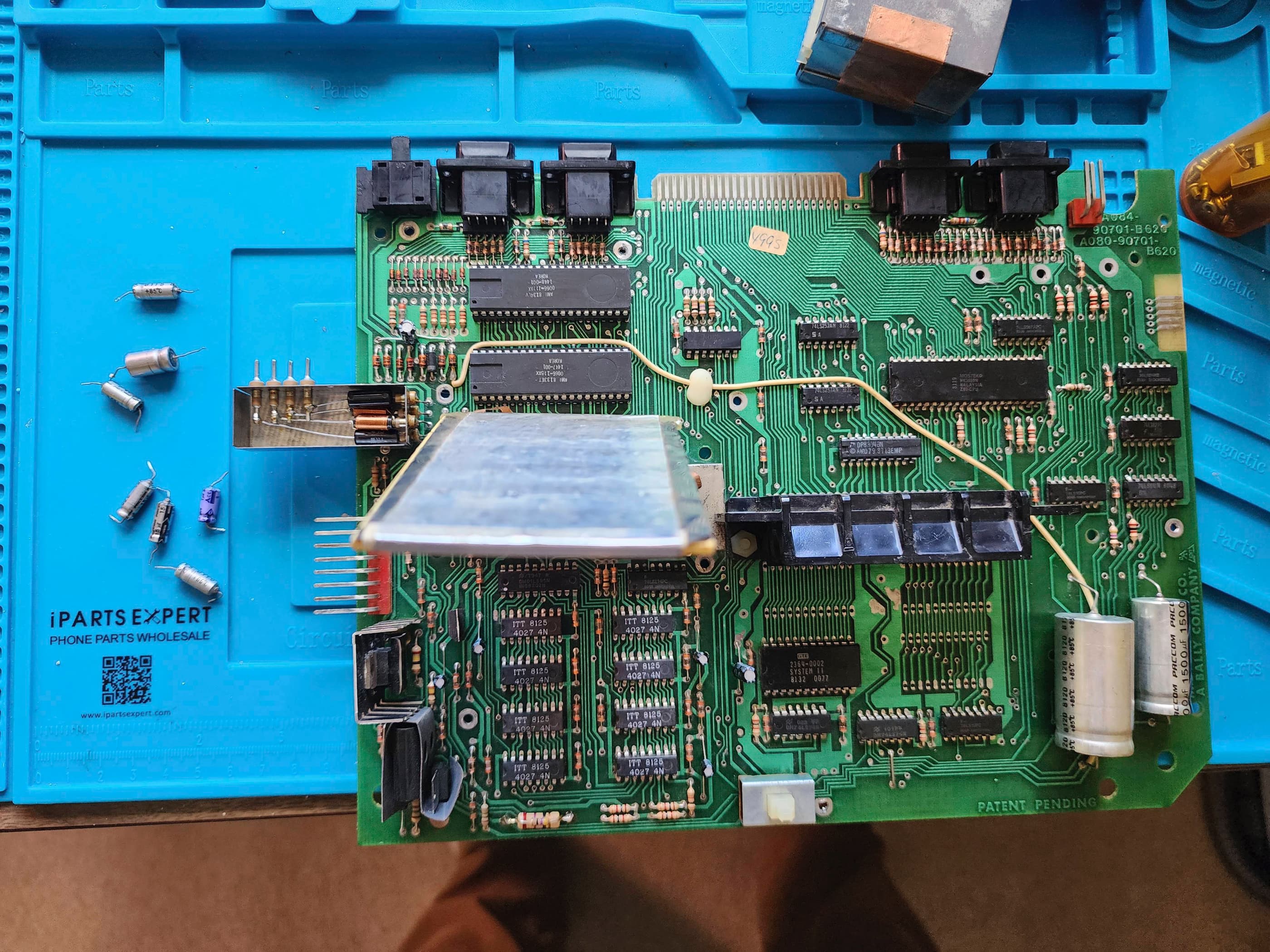


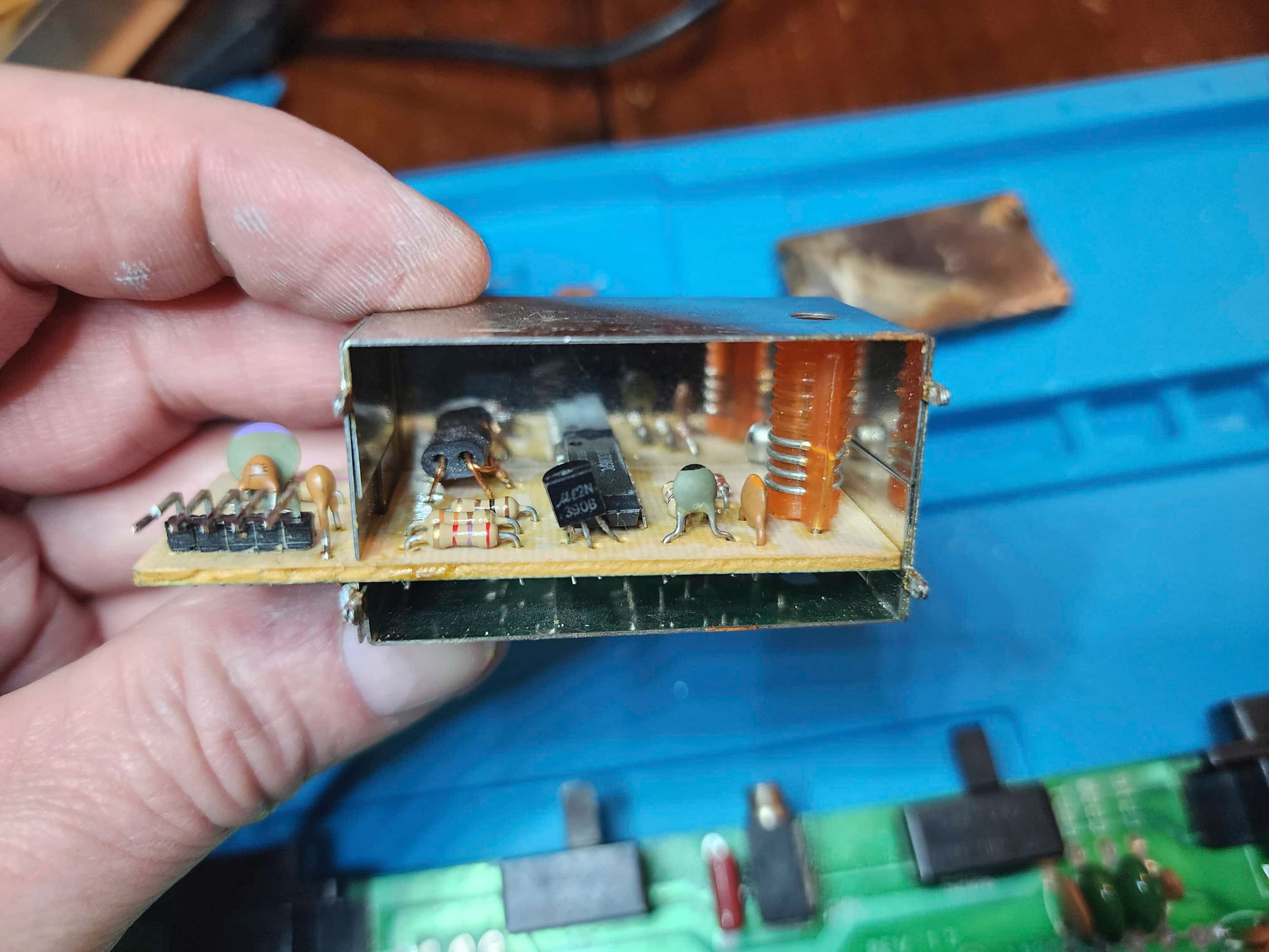
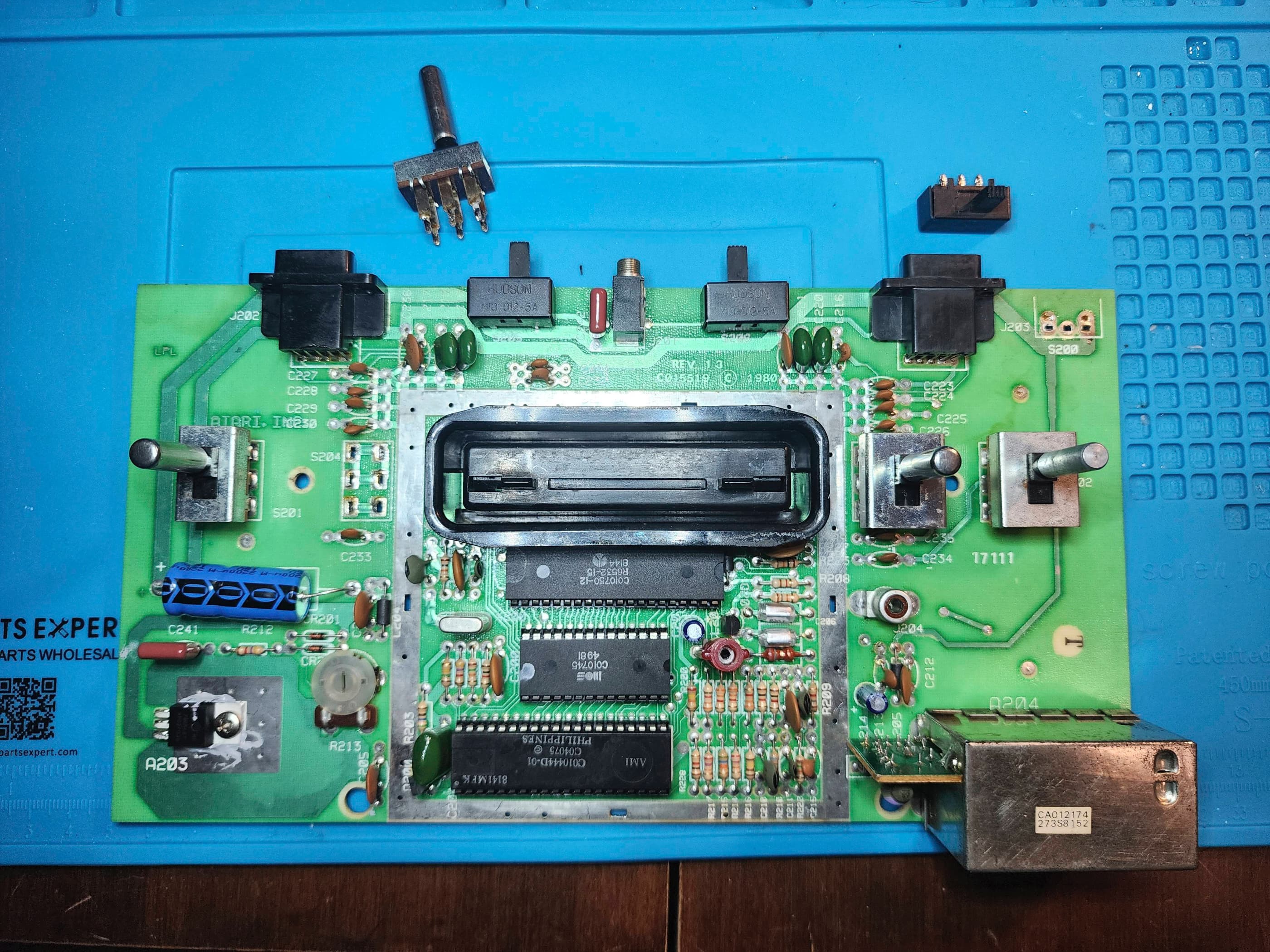
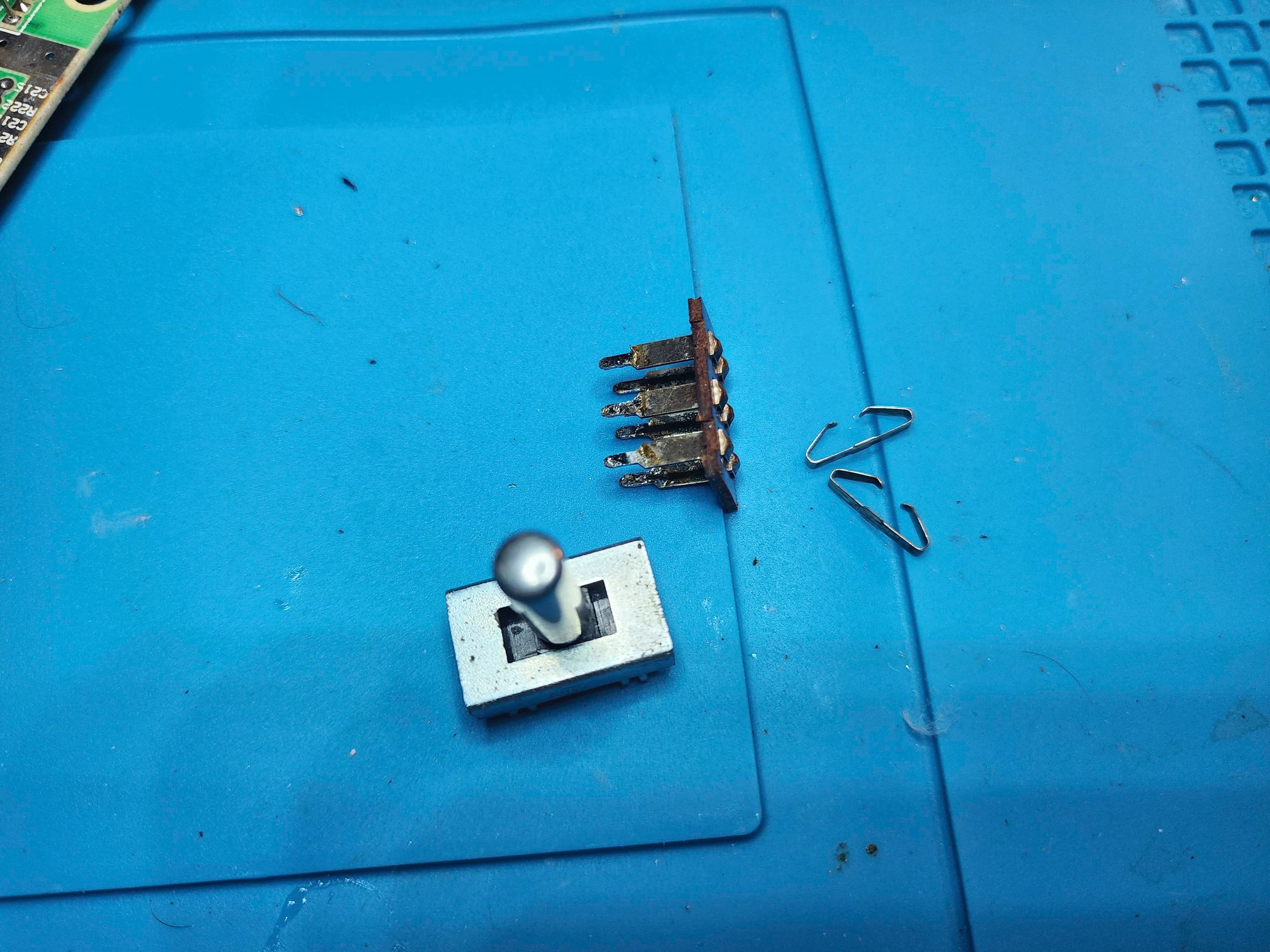
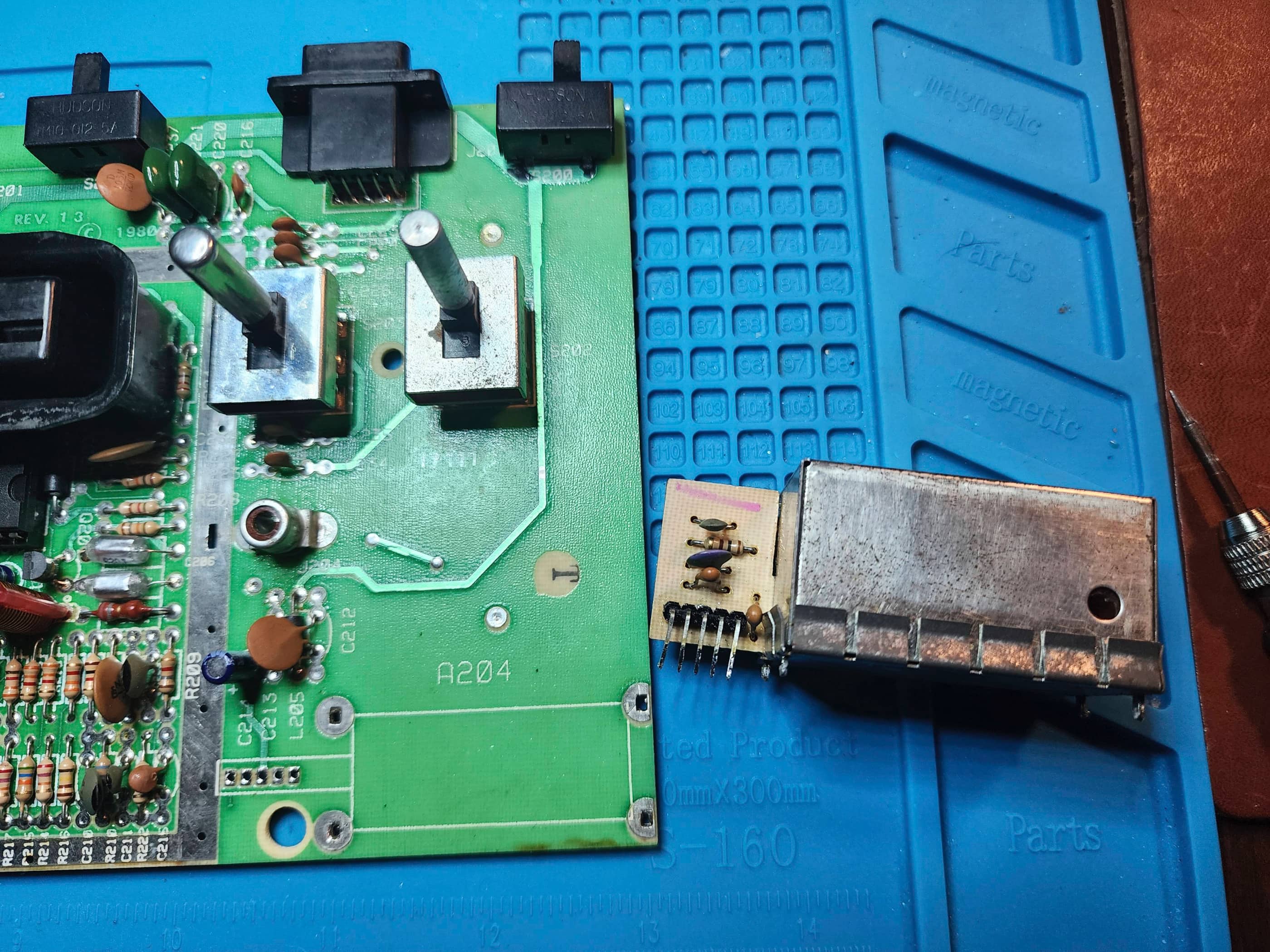
Project Details: I was super stoked to find this rare beauty! I knew from the seller that it would be DOA, but I was keen to see if it was a simple problem or something more complicated. These systems had a history of overheating due to design, and sometimes the custom chips would be wrecked by excessive heat. Moreover, the power adapter was proprietary and outputted two separate AC voltages (11.5 & 7.5) and if that was faulty, then finding a replacement would be tricky. However, before I could do anything to the unit, I had to fumigate it because it reeked of cigarette smoke (it’s a 70s console after all 😂). After a few weeks of sitting with a pan of baking soda while sealed inside a garbage bag, the Astrocade finally lost its acrid smell and I could get to work. Right away, I noticed the following: 1) the RF cable had been cut in half and then spliced with different cable; 2) when I opened the cover, I saw that the connector for the power adapter was not seated properly on the input to the rectifier; and 3) the metal ingot on the custom data chip had separated from the RF shielding, which it was supposed to be using as a giant heatsink. The good news, was that I could tell from the solder joints on the shielding, that the unit had probably never been opened before, so I got to work on desoldering the shielding.
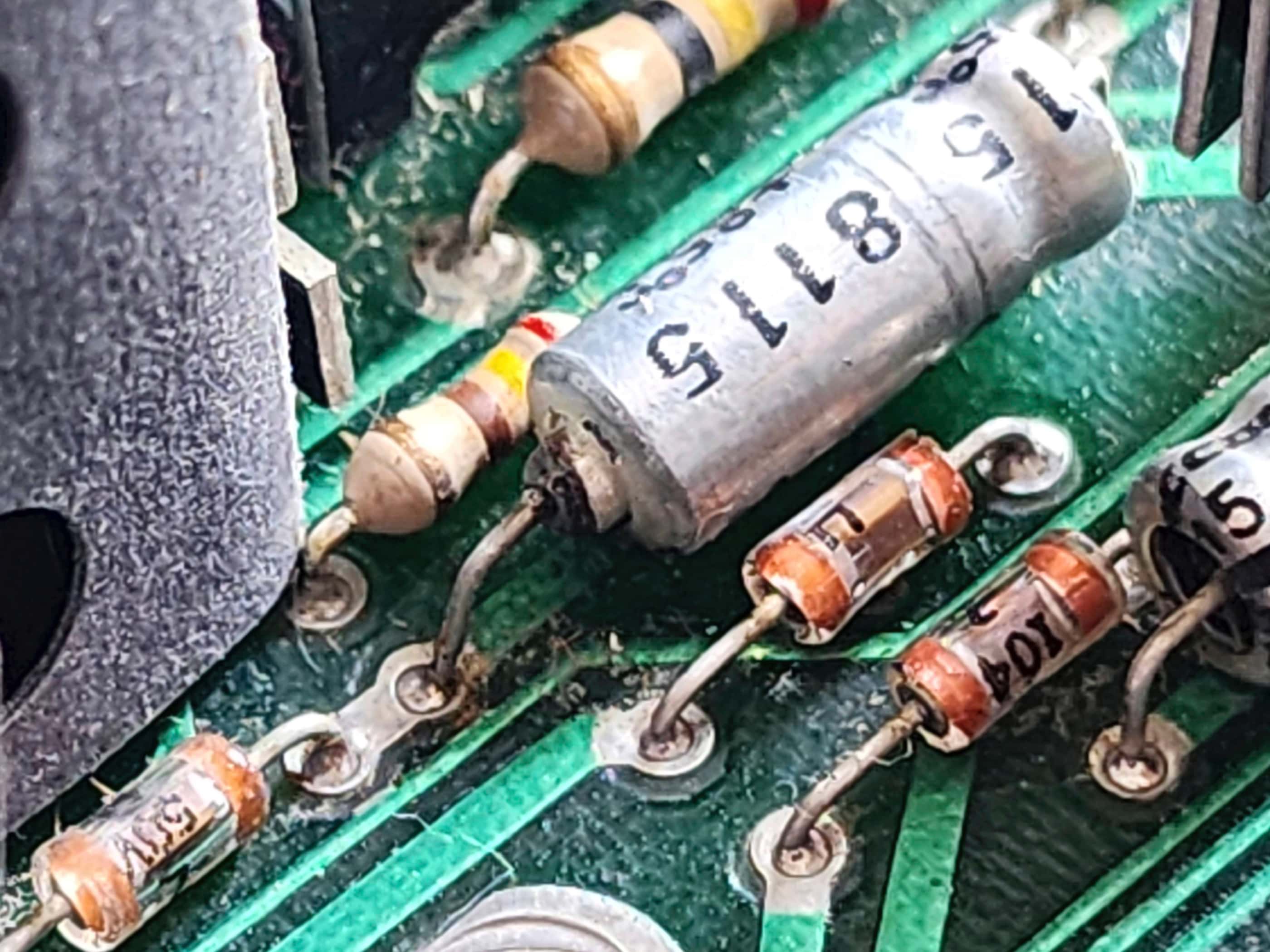
Before I went further though, I used a multimeter on the power adapter and determined that it indeed, fully functional; outputting the correct voltages. Once I’d removed all of the RF shielding I then replaced the RF cable. I excitedly powered on the system and…. nothing. I then began to test voltages coming out of the rectifier and then the various voltage regulators on the board. During this process, I noticed that capacitor C10 (16v 100 μF) had a small leak. I decided to replace all of the capacitors on the board and when all this was done, I powered it on and… it sprung to life!! 👏 😃 I then tested some of the cartridges and found that some worked and others didn’t.
Next, I undertook my detailed cleaning regiment plus I added heatsinks to all three of the custom chips; however, I could not remove the ingot from the custom data chip, so I ended up putting the heatsink on top of the ingot. Not ideal but acceptable – and it still fit under the ribbon cable. I also rebuilt three of the non-working controllers using a pair of non-working controllers I found online. I disassembled, cleaned, and reassembled all of the cartridges to see if that helped. It did for one of the games. When I reassembled the entire system, I did not include the RF shielding to promote better airflow. As the metal keypad had come unglued, I glued that back onto the case. The system now works wonderfully and I’m consistently blown away by the depth and quality of the sound compared to its peers. The innovative controllers are also surprisingly responsive. 😀
Parts & Products Used: 99% isopropyl alcohol; Chemical Guys Natural Shine; replacement RF cable; double-sided thermal tape; DIP 40 aluminum heatsinks (3); electrolytic capacitors (axial) – 10v 10,000μF (1), 25v 1500μF (1); electrolytic capacitors (radial) – 16v 100 μF (1), 50v μF (1), 25v 22μF (5); parts from an additional pair of controllers; E6000 adhesive

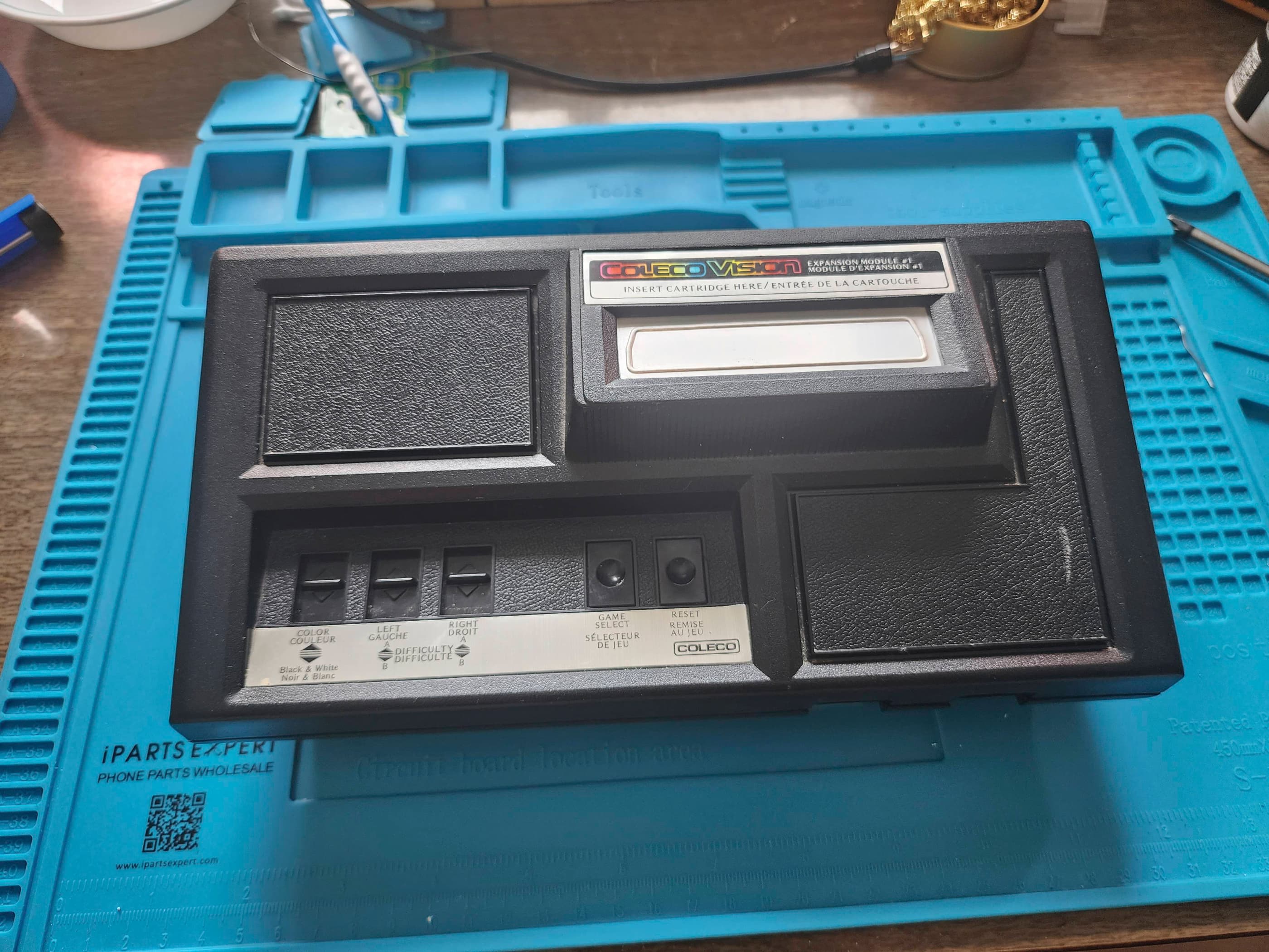
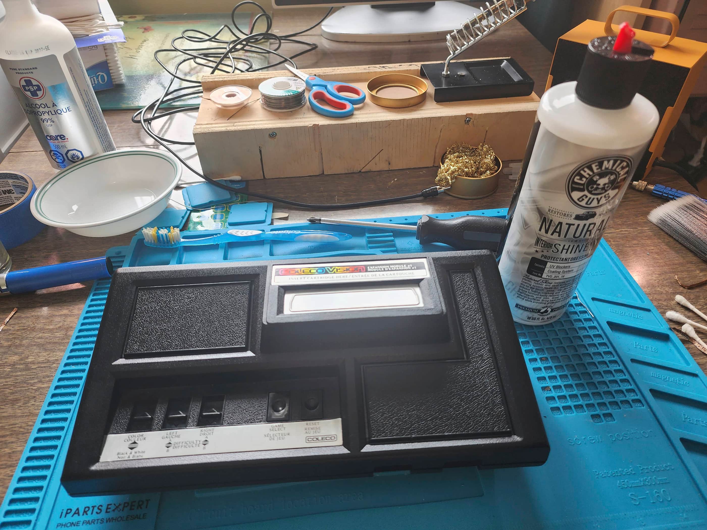
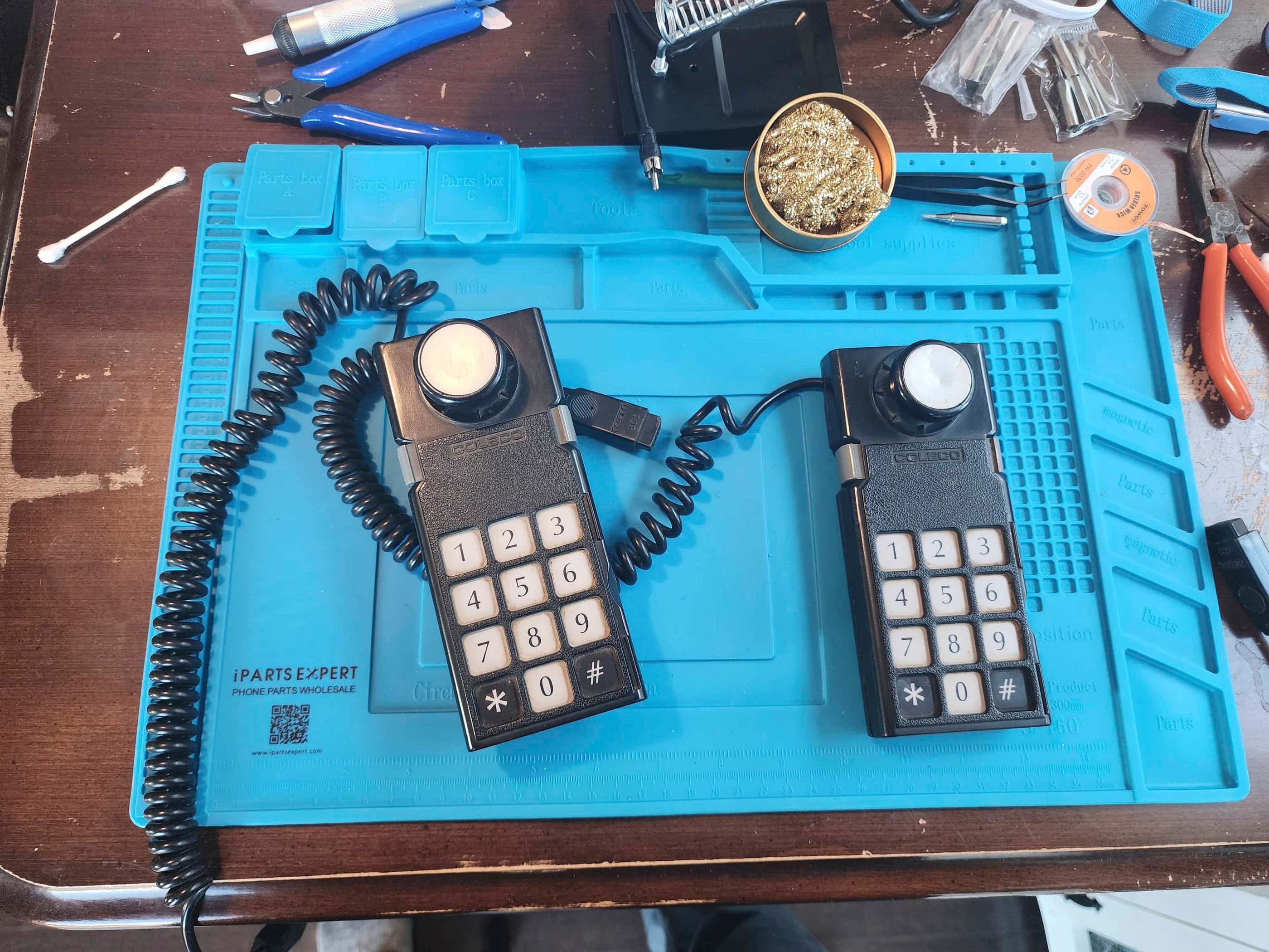
Coleco Gemini
Years (1982 – 1984?)
Interesting fact: The Gemini originated as Expansion Module #1 for the 1982 Colecovision; allowing it to play Atari 2600 games. Atari was livid and sued Coleco for patent infringement, while Coleco argued that the Module was simply built using off-the-shelf spare parts and countersued. The lawsuits were bitter, but eventually Coleco agreed out of court (even though it had a ruling in its favour) to pay a licensing fee for the use of Atari’s patents. This resulted in Coleco moving ahead with the Gemini as a stand-alone Atari 2600 clone. (source)
Condition When Acquired: Non-Functional (DOA)
Current Condition: Fully Functional


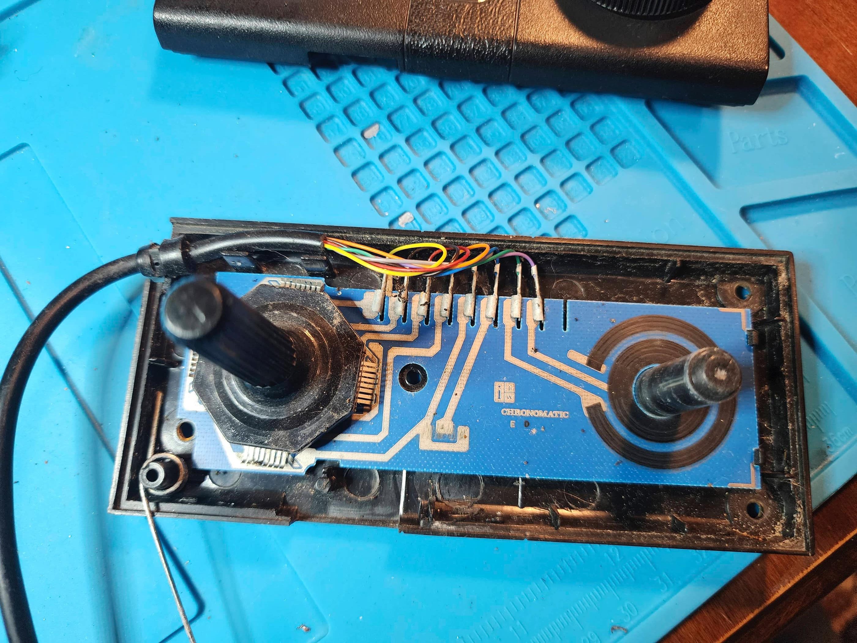
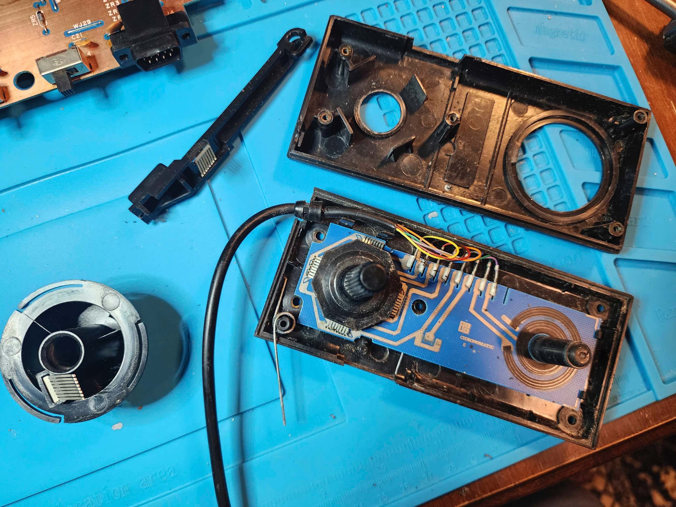
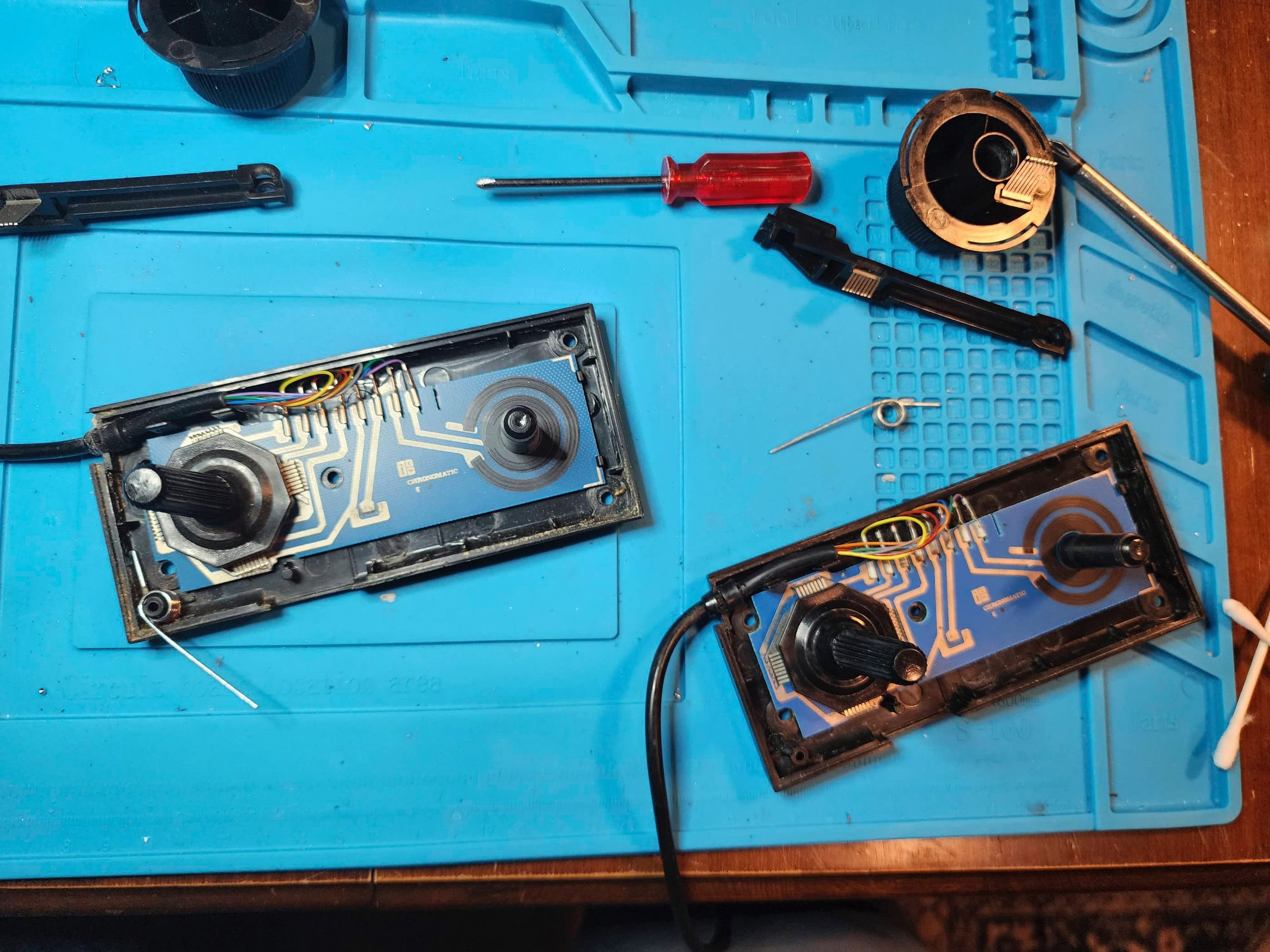


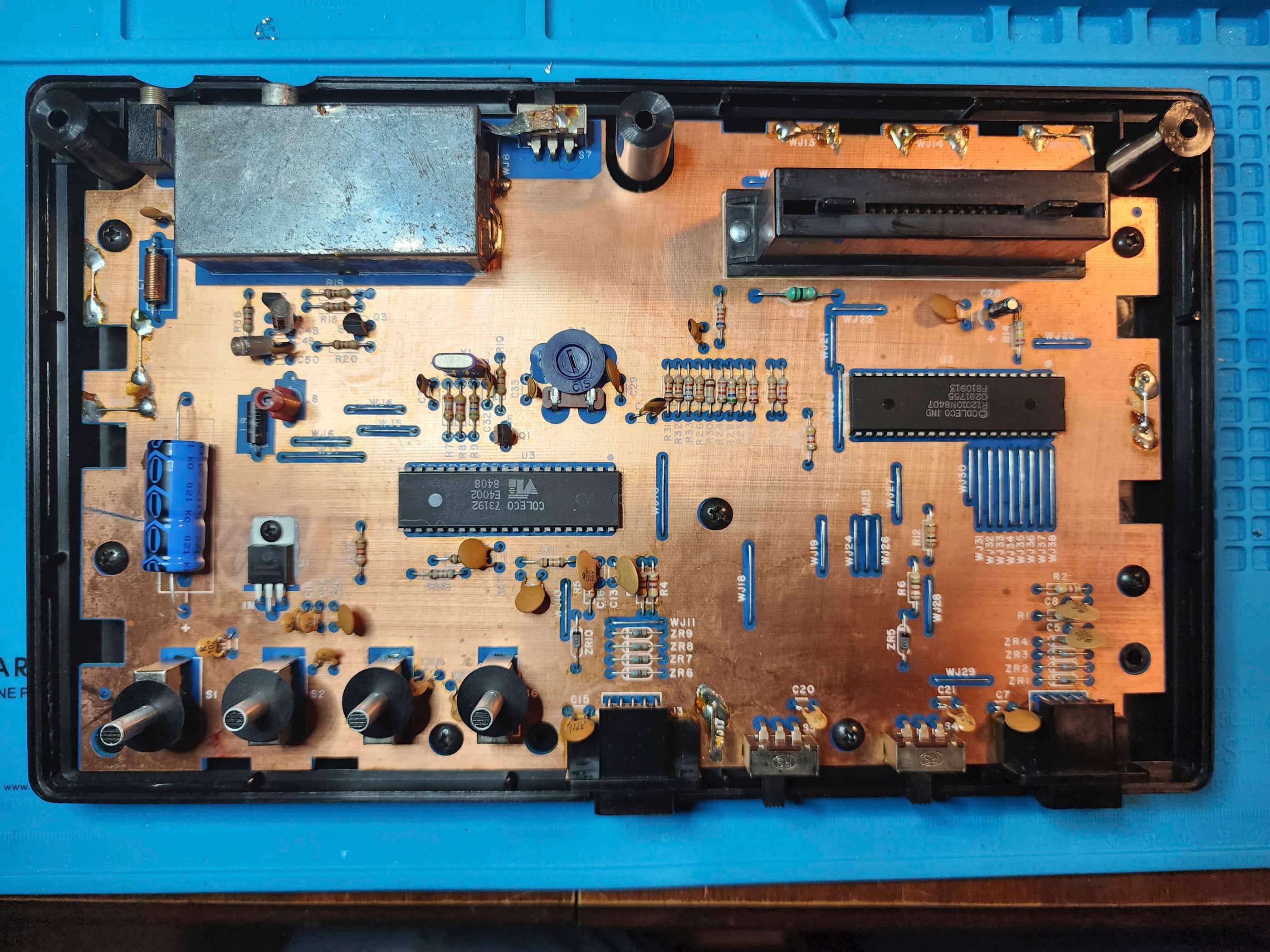

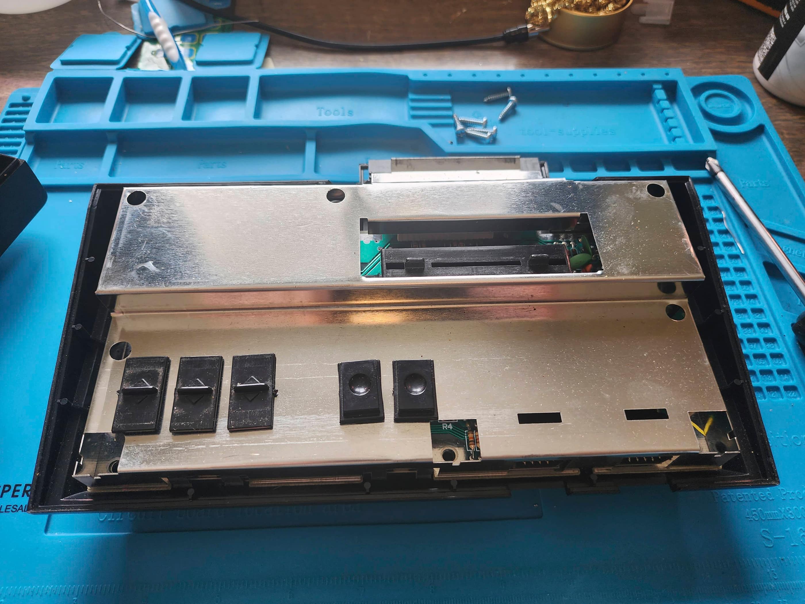
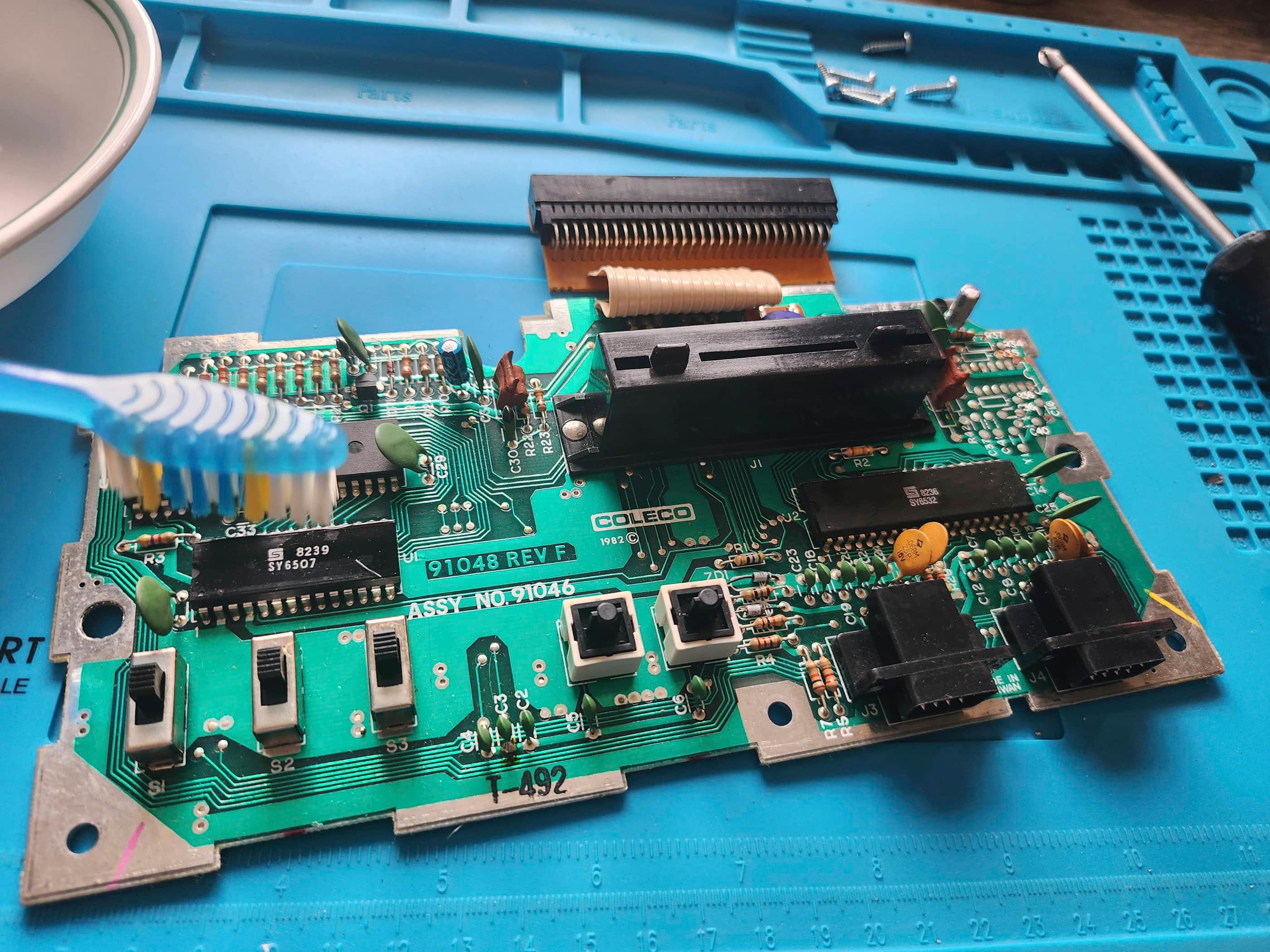
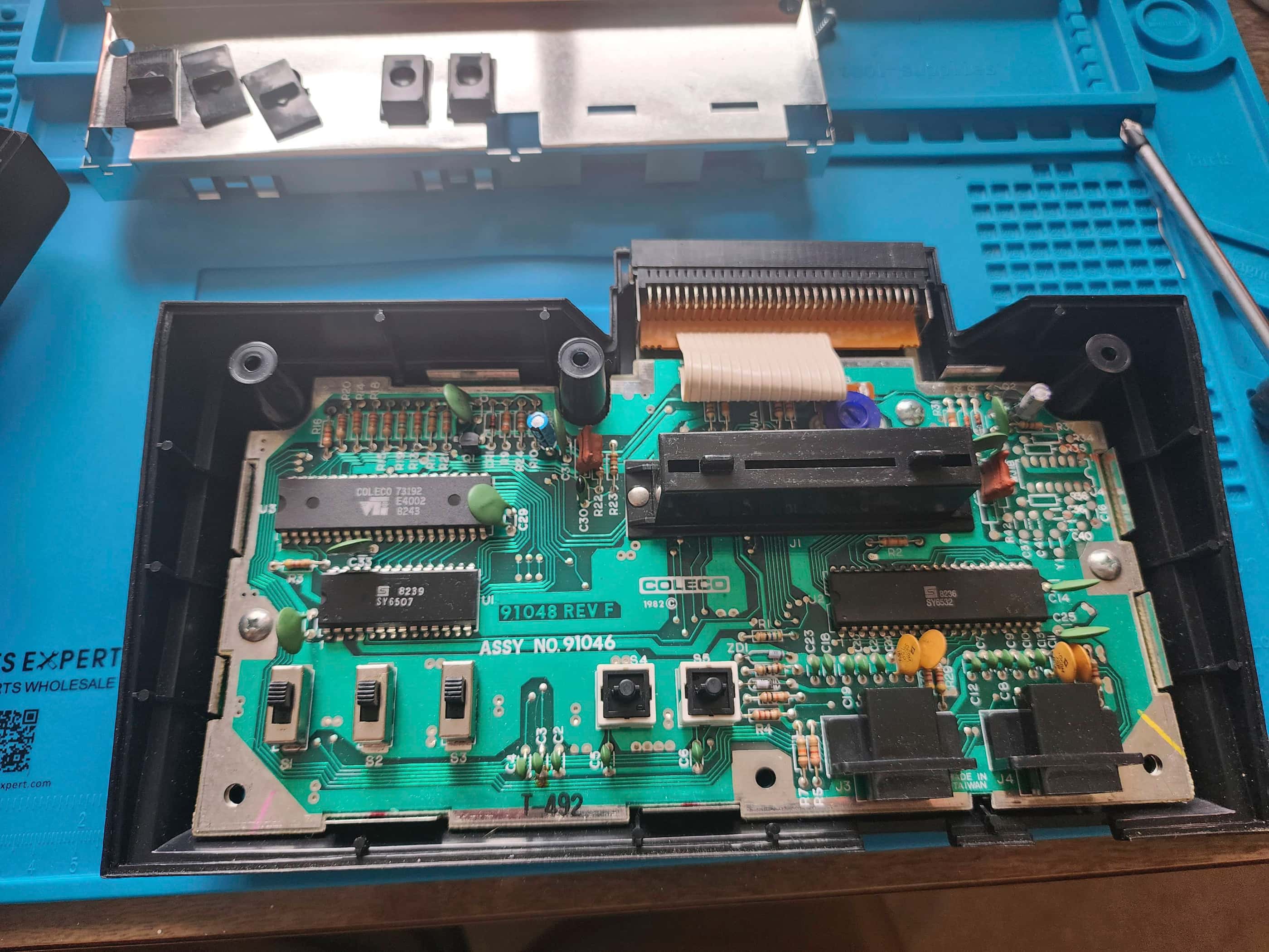
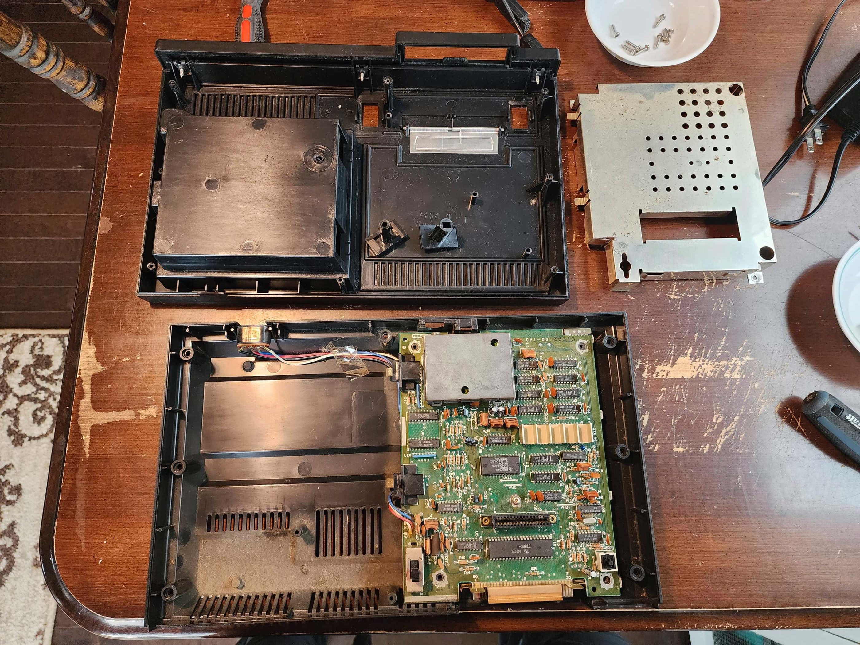
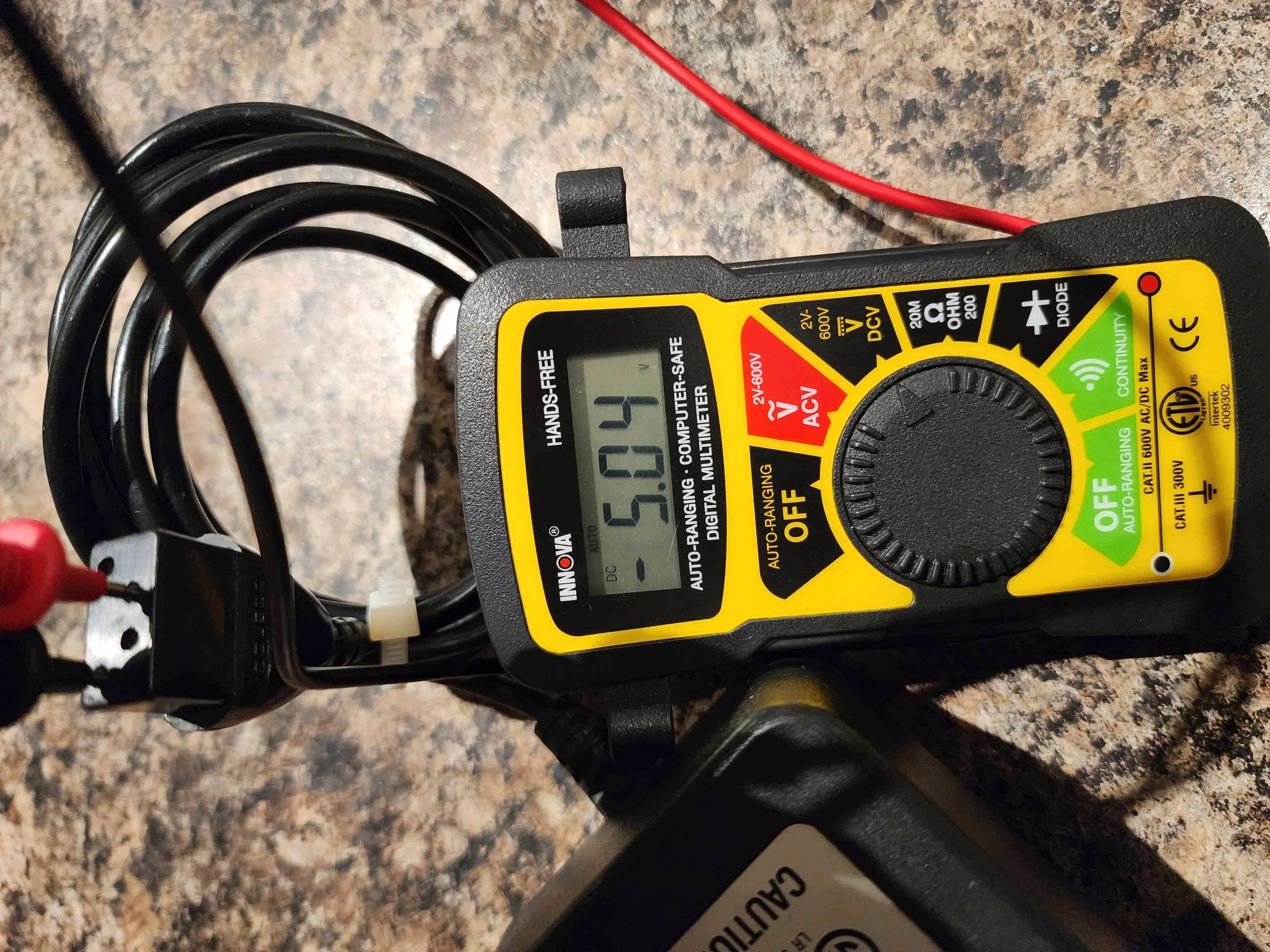
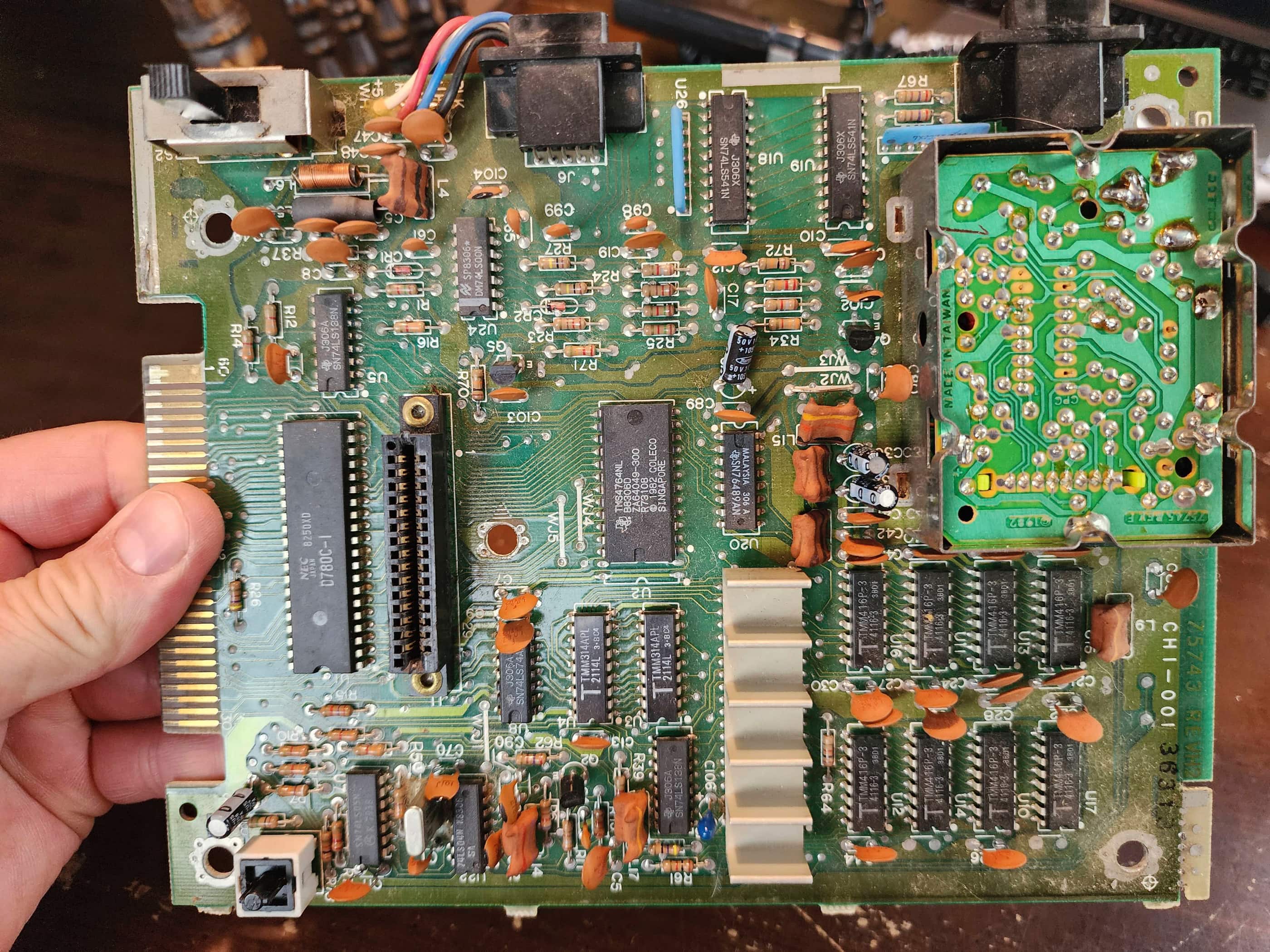
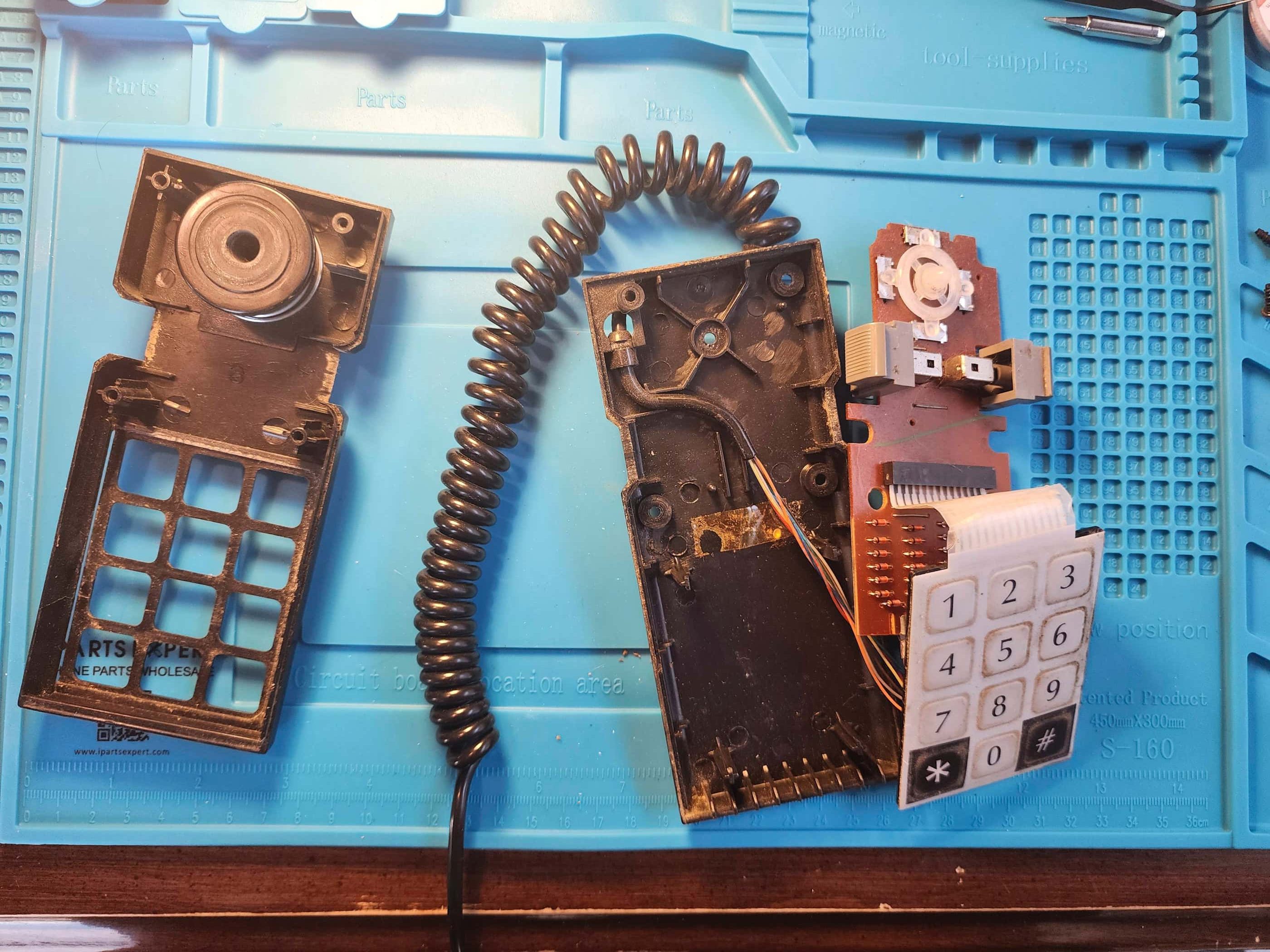
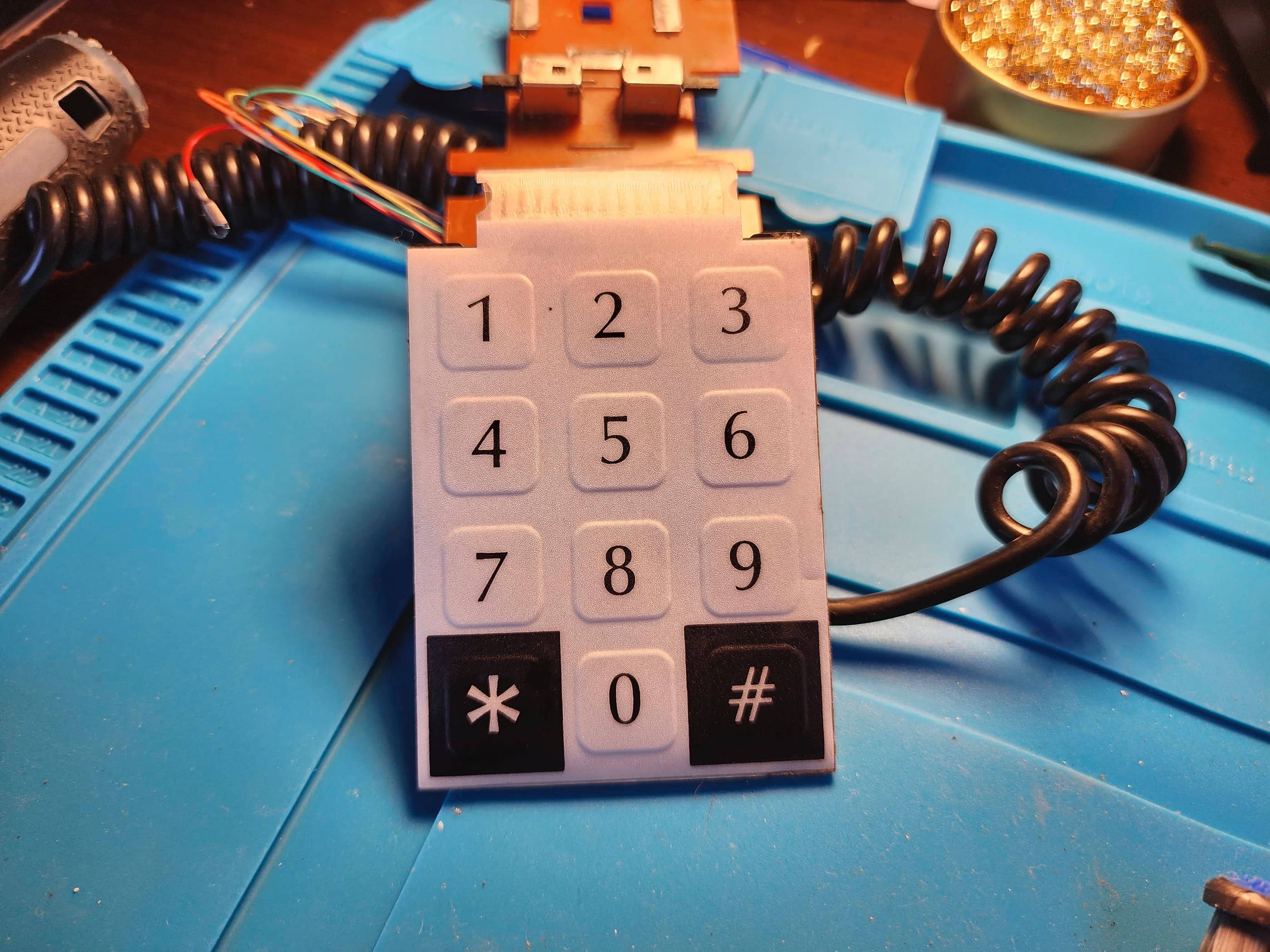
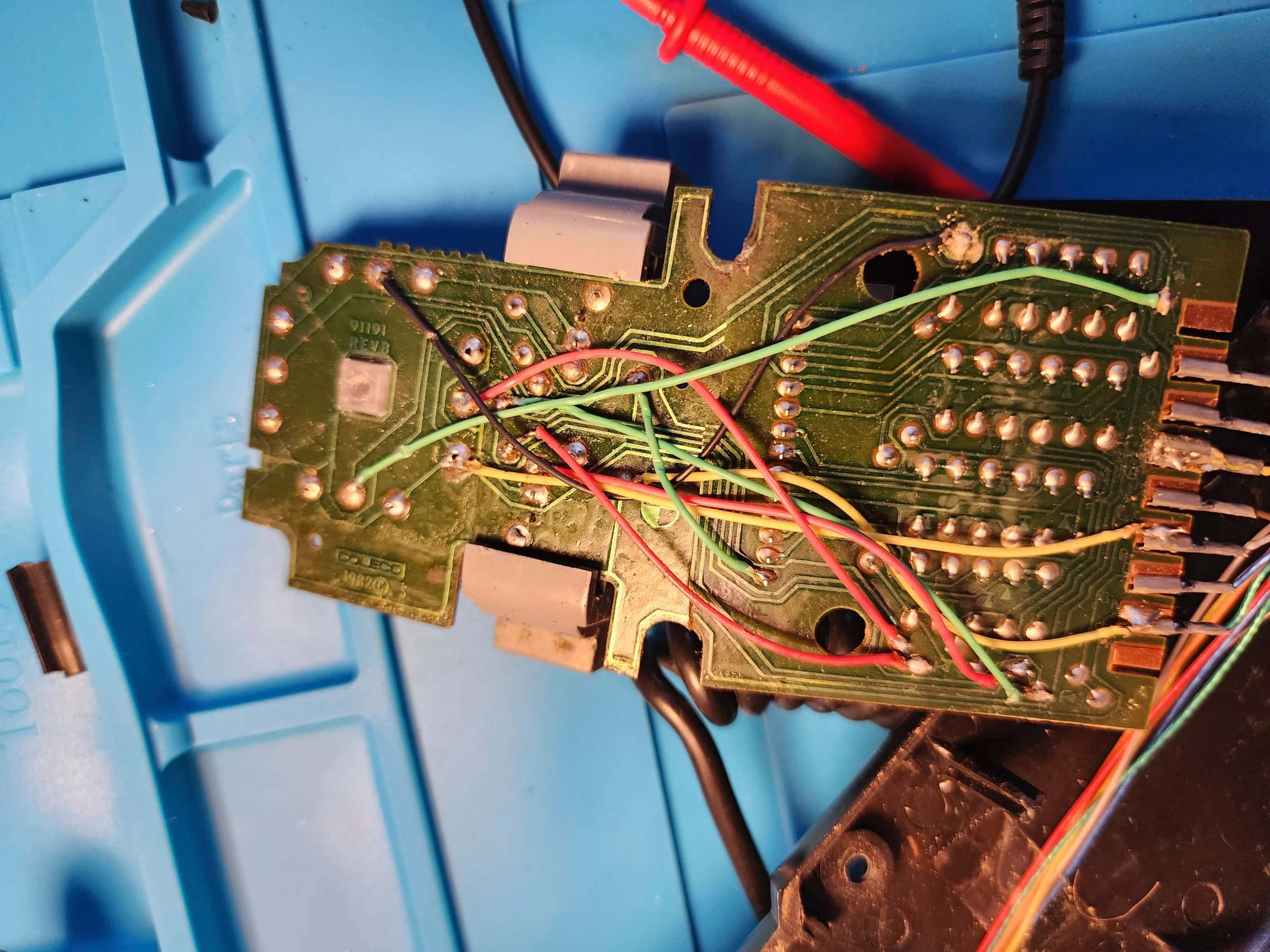
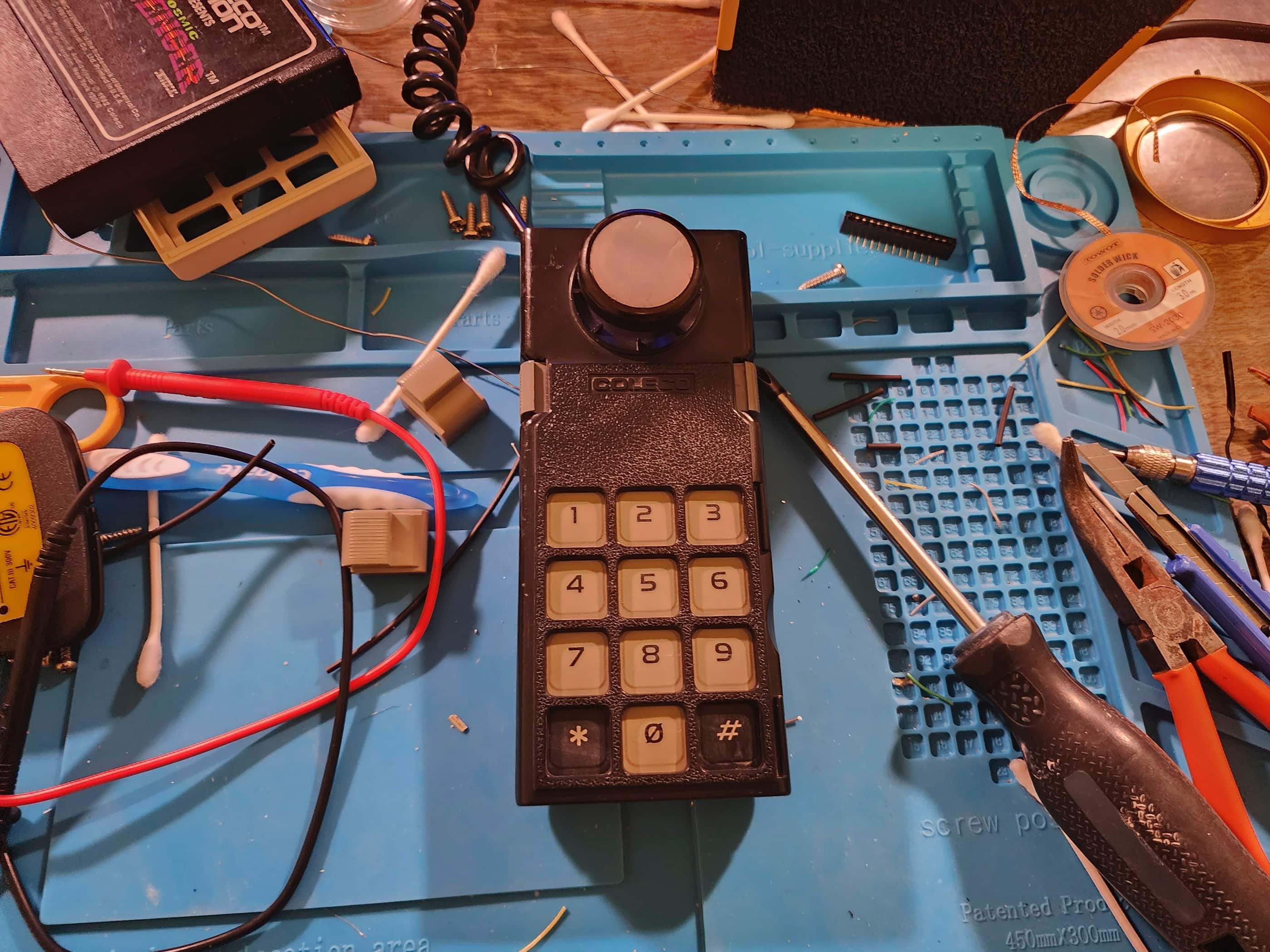
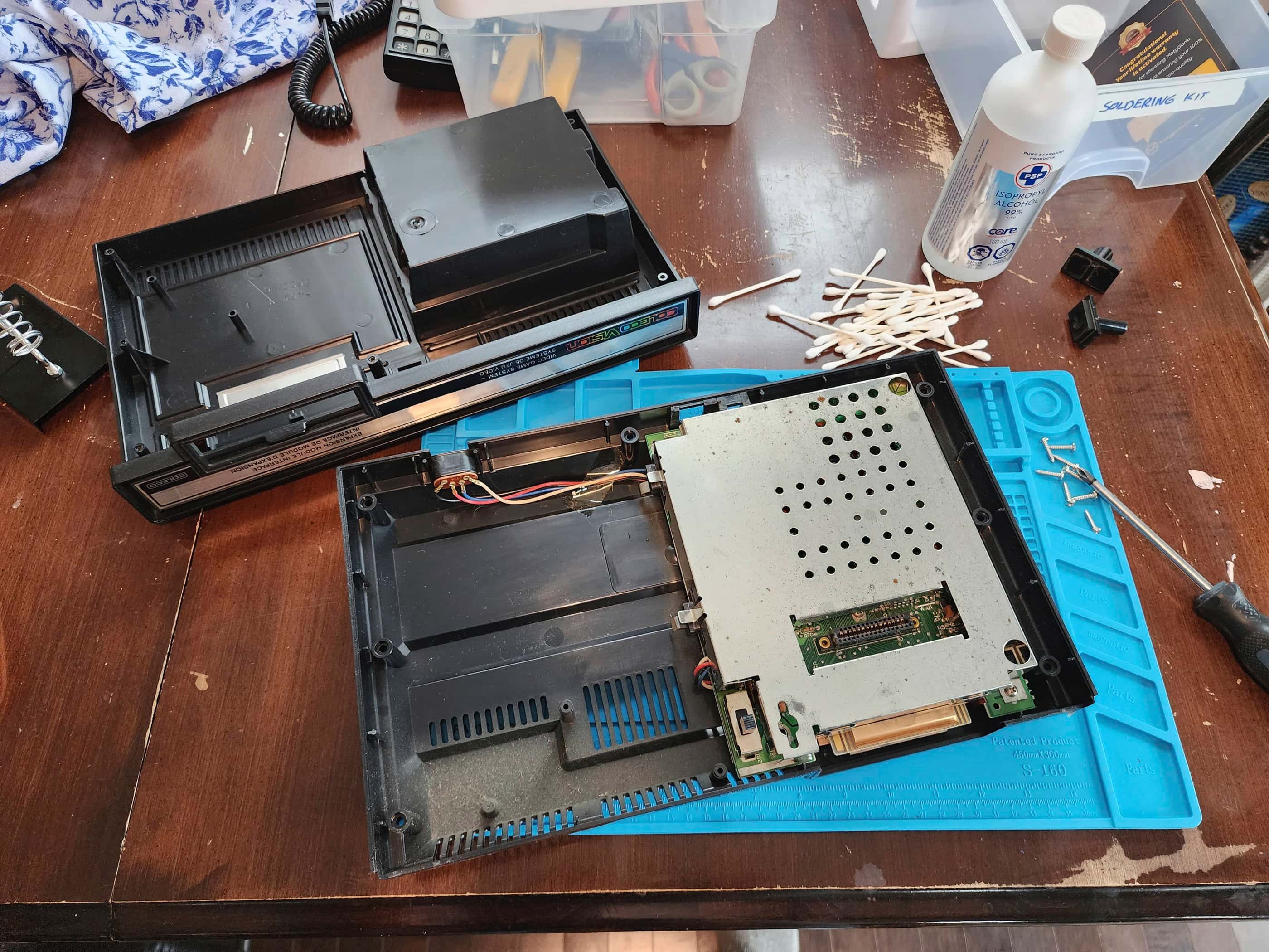
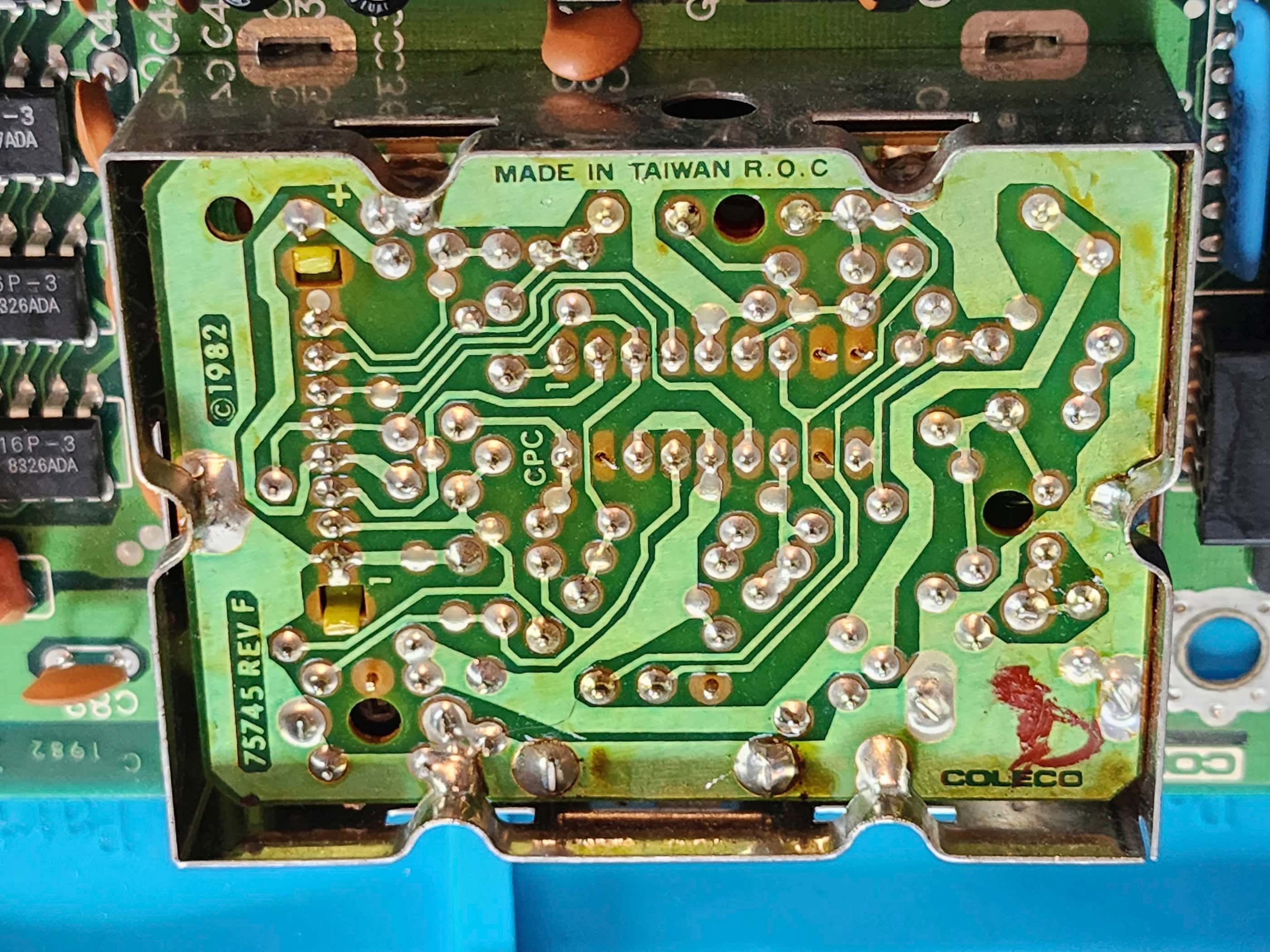
Project Details: I’d been looking for a complete Gemini system for quite sometime, but until this unit, I’d never found one that was under $50 which included both the original joysticks. I’d seen them at that price with Atari joysticks, but not the Coleco ones. As it was so cheap, it also came with the ‘untested’ qualification which I’m good with. As it didn’t come with a power adapter, I used one that I had on hand and that I knew was working. I popped in a cartridge and turned the system on and… crickets. The unit was DOA. Several attempts later and still nothing. I opened the system up, removed the board from the casing, and desoldered the shielding from the RF modulator. I then proceeded to check voltages and continuity across the board. My first stop was to check the input and output voltages on the 7805 5v regulator. It passed with flying colours. I then checked the power switch and could see a correct voltage passing along the trace to the input on the 7805. Hmmm…. 🤔 I spent quite a bit of time checking voltages on various parts of the board and nothing seemed out of place. I also conducted continuity checks and looked for cracked solder joints under a magnifying glass. Nothing. As I was flipping the board over, my hand bumped the power switch and for a brief instance, a grey screen appeared. This was progress from the blank screen. I refocussed on the power switch and discovered that if I pushed the switch slightly to the side, the grey screen would come back. I was in the middle trying this for the second time when suddenly, Missile Command, displayed on my screen. Now we were making progress!
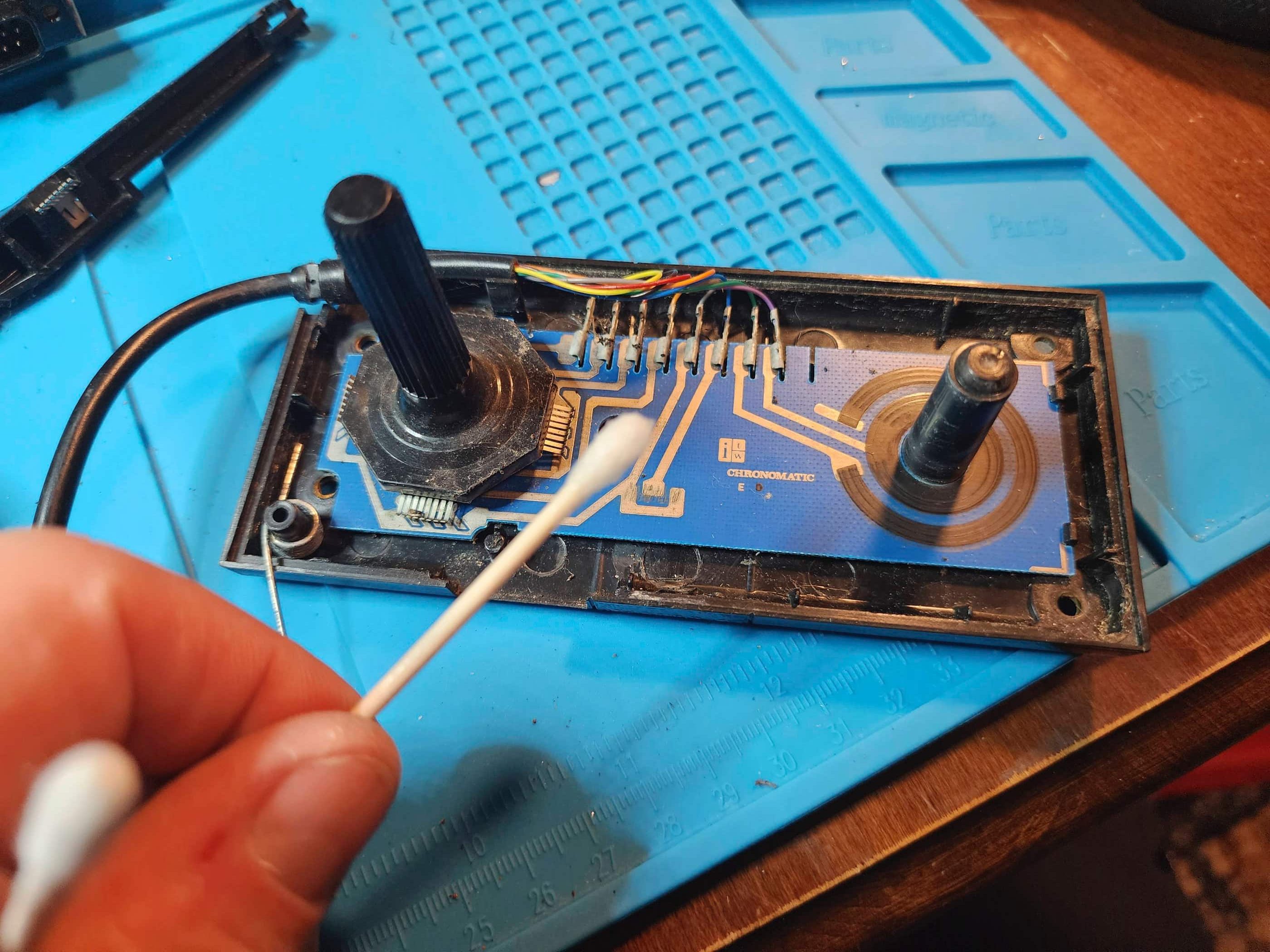
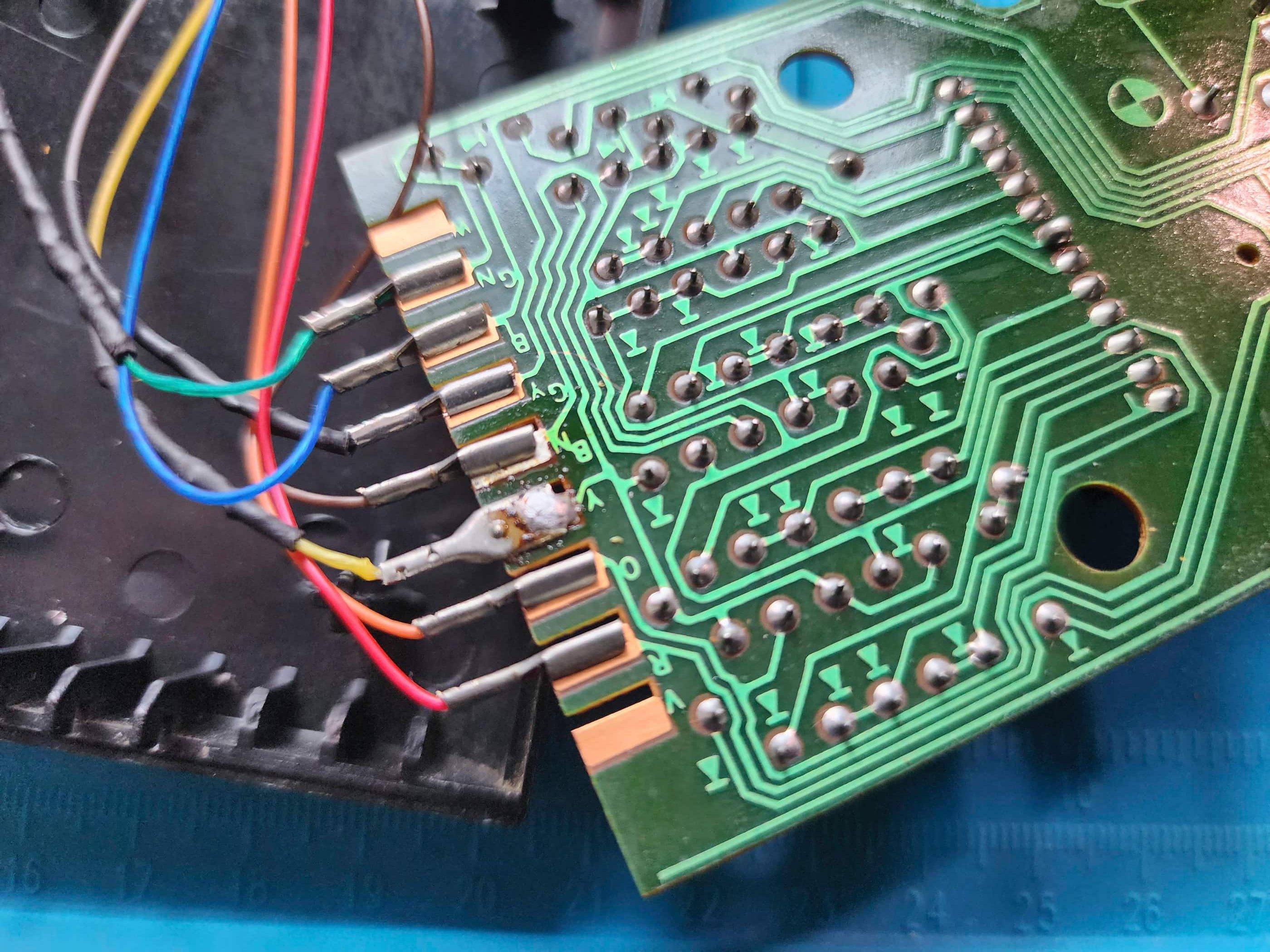
The issue was with the power switch. It was letting voltage through when it was on, but unless I pushed sideways against the toggle, nothing would appear on the screen. I taped the power switch for further testing and plugged in a joystick to the left port. Missile Command displayed great, but the joystick would only let me move up, down, left, and fire. I tried the second joystick and the same thing happened. I plugged in an Atari joystick and the same thing happened. Something was wrong with the port or the board. These machines have notoriously bad joystick ports, so I set about continuity testing and looking for cracked solder joints under a magnifying glass but I couldn’t see anything. To give my mind a break from that problem, I decided to try and fix the power switch by desoldering, disassembling, cleaning the contacts, reassembling, and soldering it back onto the board. Through this process, I was able to tighten the side-to-side play of the switch by pushing the contact plate closer to the metal casing and bending the clamps to hold it in place. This pretty much eliminated any excess play and the system now powered on and off as it should.
One issue fixed. For the joystick port, I continued to do continuity checks with a focus on the pins 4 & 8 that control movement to the right. Nothing came back indicating there was a problem, but I still decided to reflow and add new solder where the port pins join the board. I was surprised when the existing solder disappeared into the hole as soon as my iron touched it. I proceeded to reflow and add new solder to all the pins on both ports. I then tested it with a couple games. Both joysticks now had full movement. The second issue was now fixed. I then disassembled and cleaned the joysticks, noting that at some point, they had come in contact with water. I also discovered the exoskeleton of a bug in one. 😯 After cleaning I reassembled the joysticks and then tested them. The joysticks and paddles worked great. I decided that since the unit was still open that I’d recap it (using a 50v 4.7μF capacitor to replace the original 35v 4.7μF one) and also replace the 7805 regulator. Once done I tested it with several games and then reassembled it. The Gemini is now a fully functioning system. 🙂
Parts & Products Used: 99% isopropyl alcohol; Chemical Guys Natural Shine; dielectric grease; thermal paste; 7805 +5v regulator (1); electrolytic capacitors (axial) – 16v 2200μF (1); electrolytic capacitors (radial) – 50v 4.7μF (1); replacement 9v 500mA power adapter

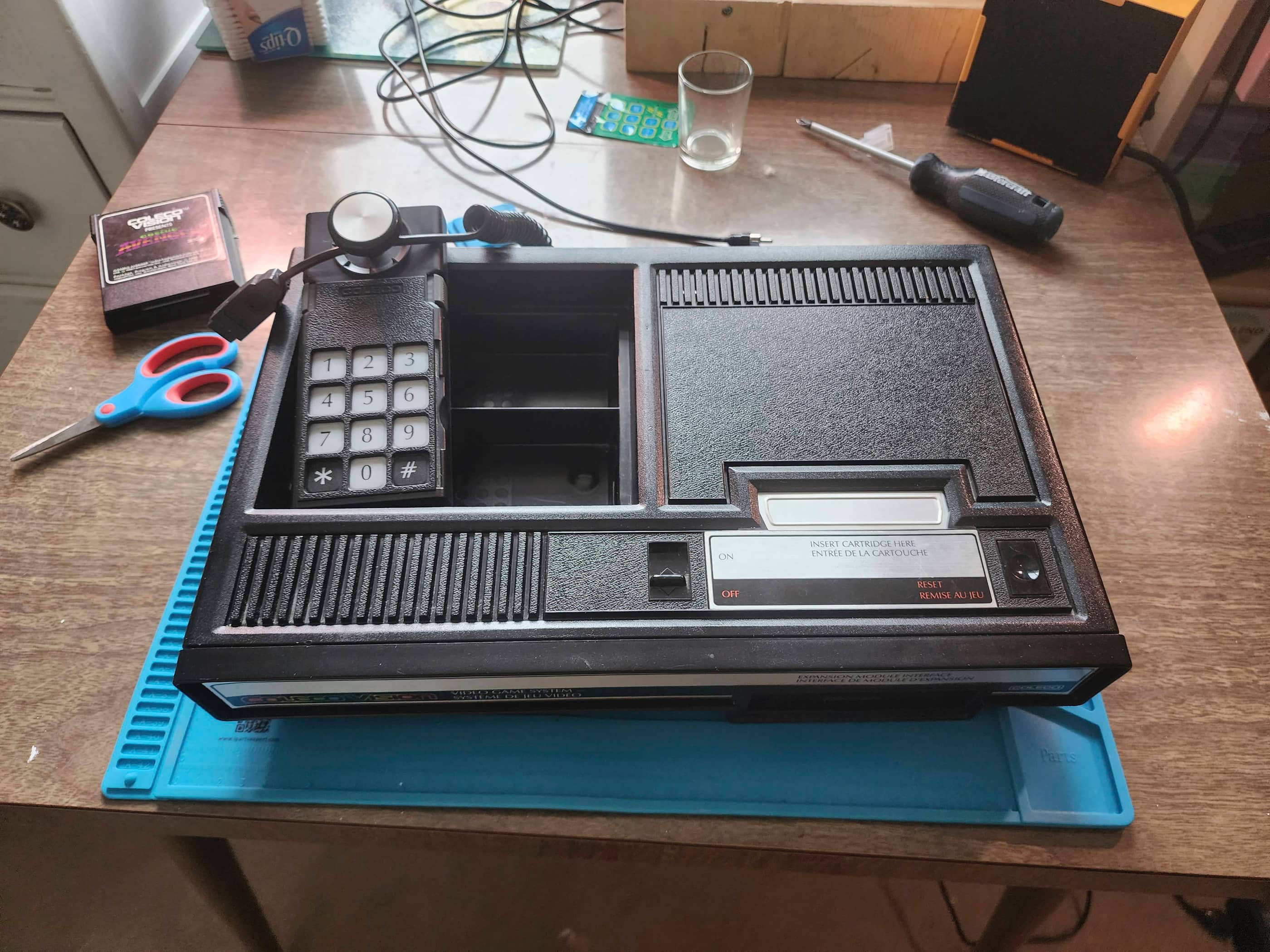
ColecoVision (#1)
Years (1982 – 1985)
Interesting fact: The ColecoVision was one of the first consoles to offer an arcade gaming experience and it came packaged with the most true-to-arcade version of Donkey Kong ever released to prove it. (source) It was more powerful than the Atari 2600 and Mattel’s Intellivison, and had the capability to offer expansion modules. (source)
Condition When Acquired: Partially Functional – graphics and sound issues
Current Condition: Fully Functional

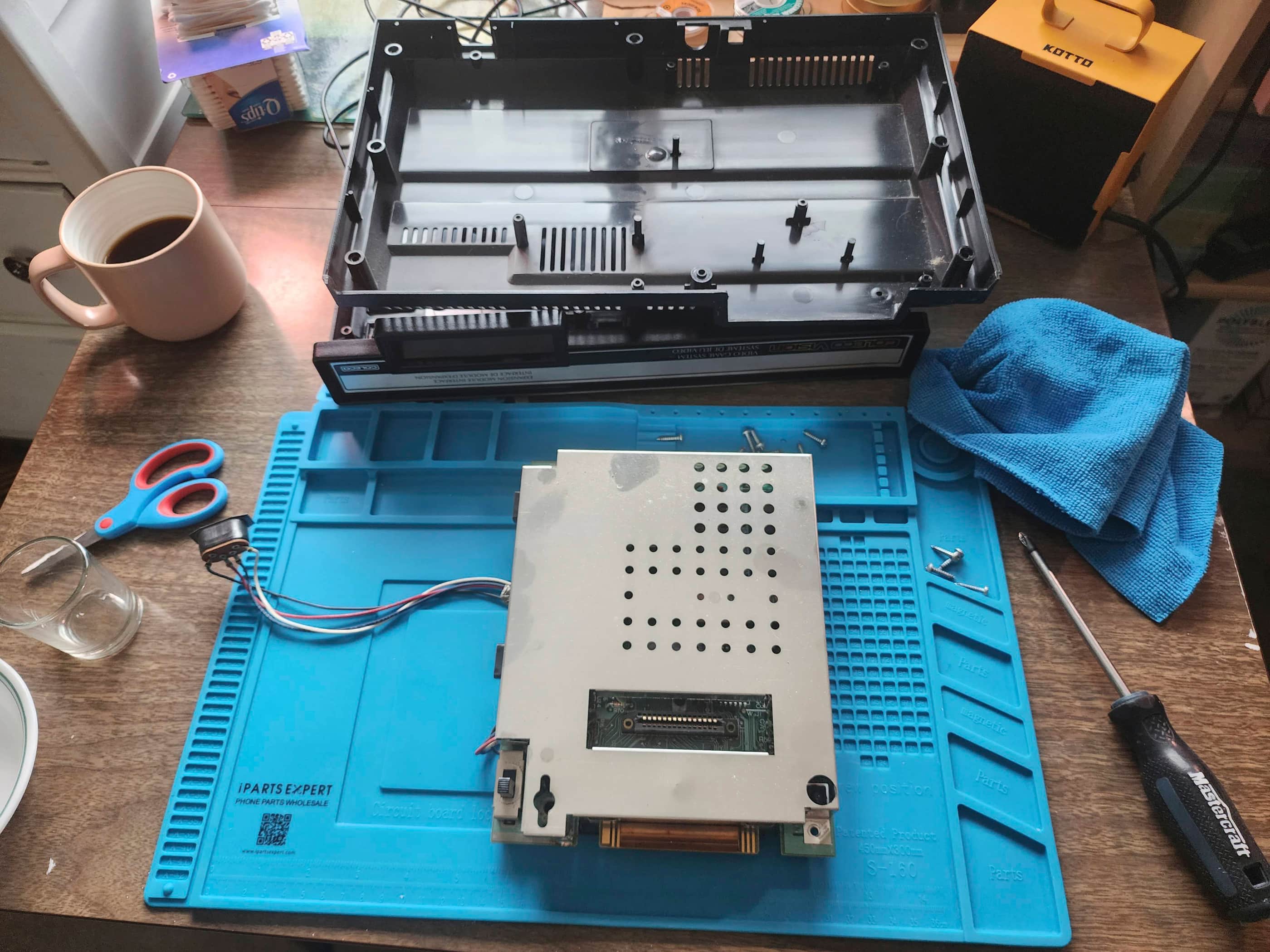
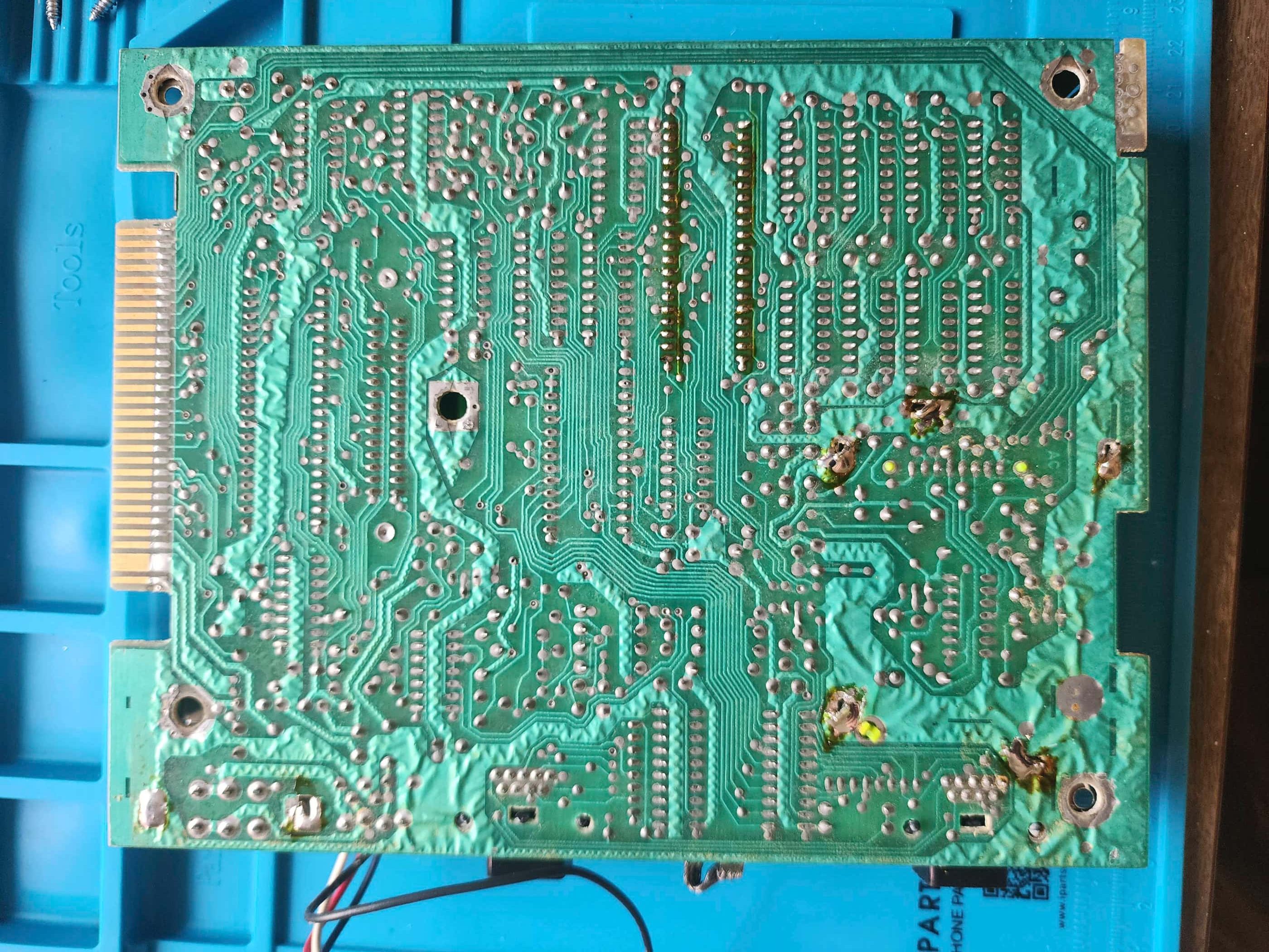
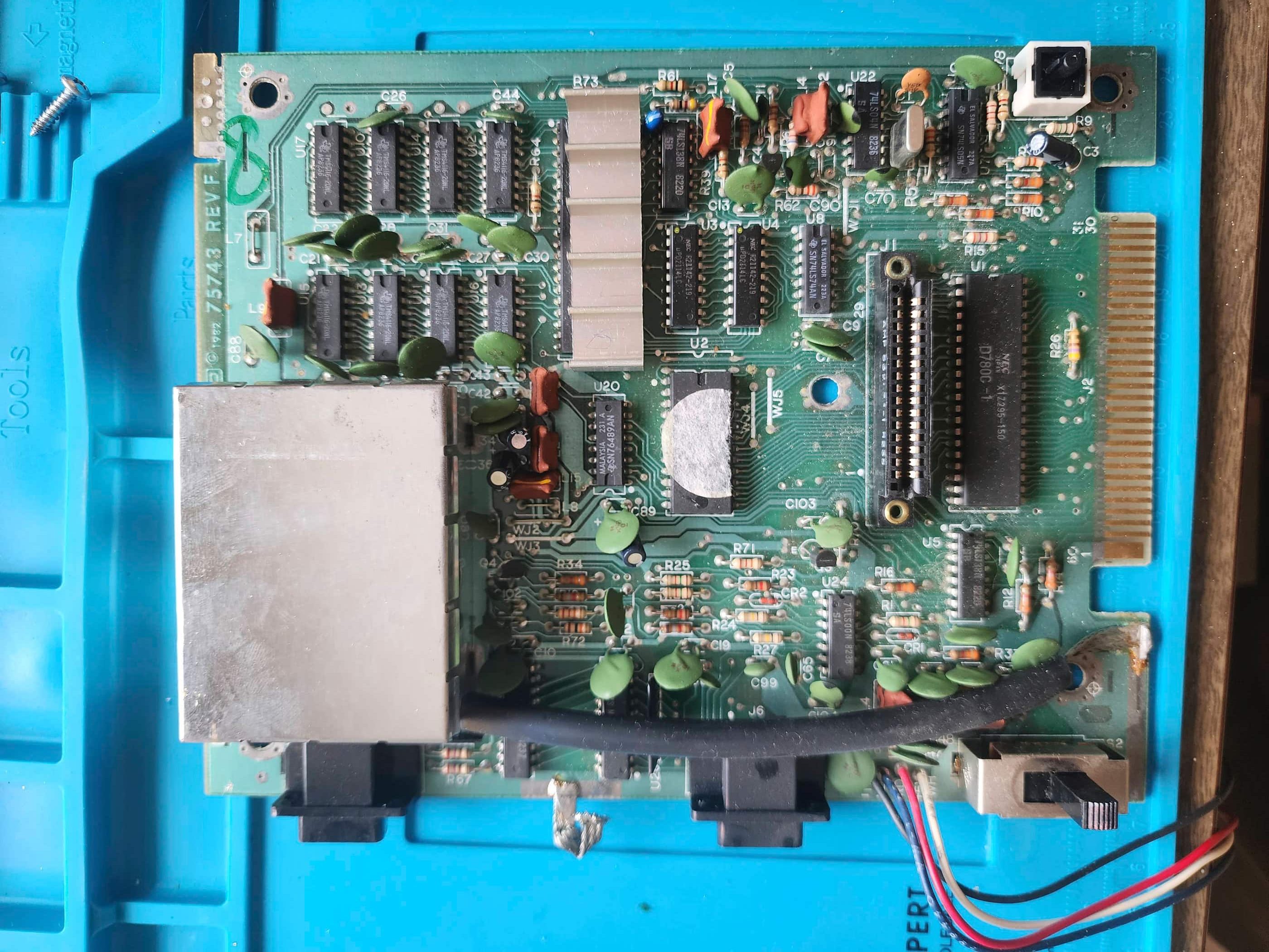


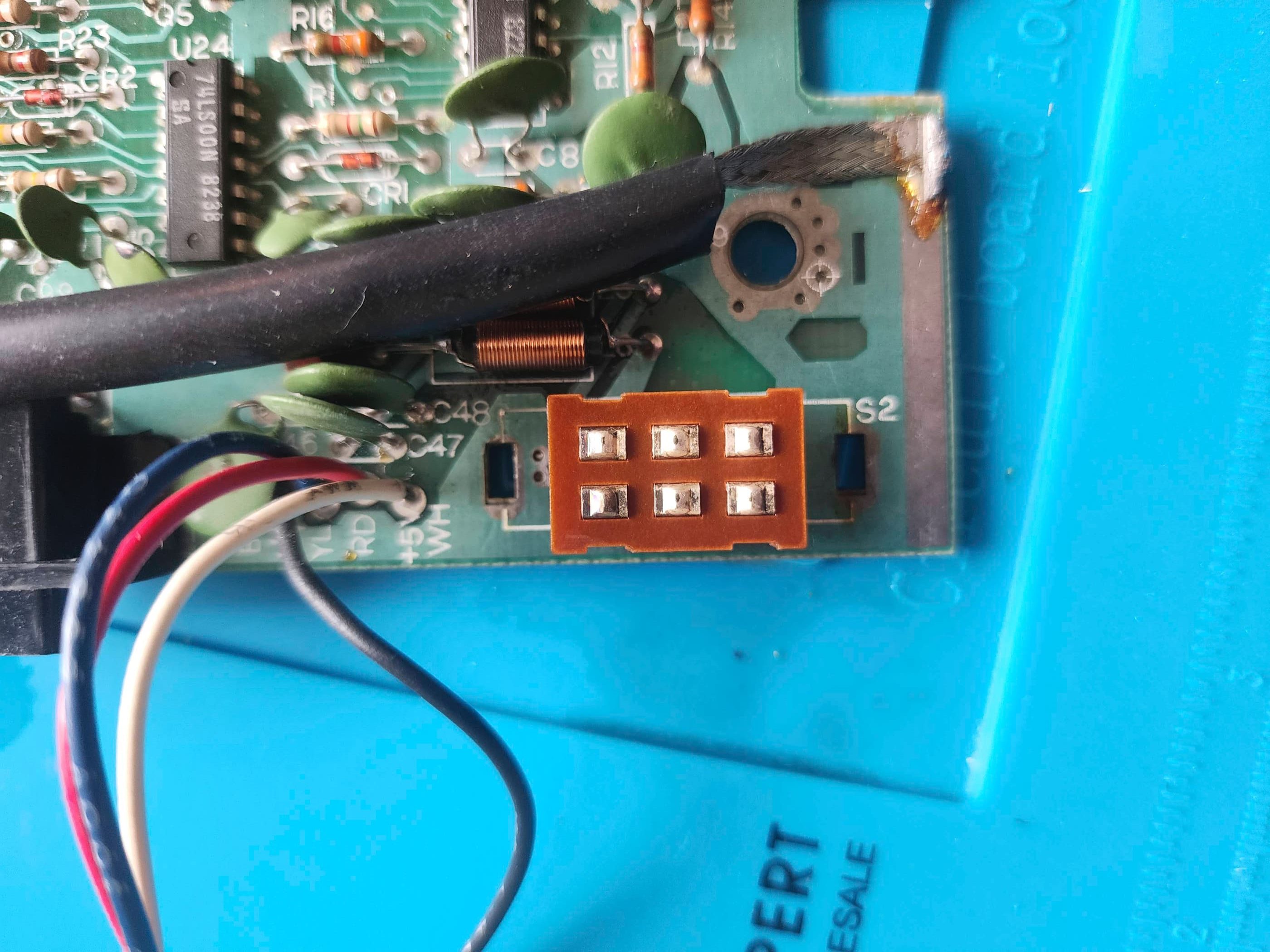


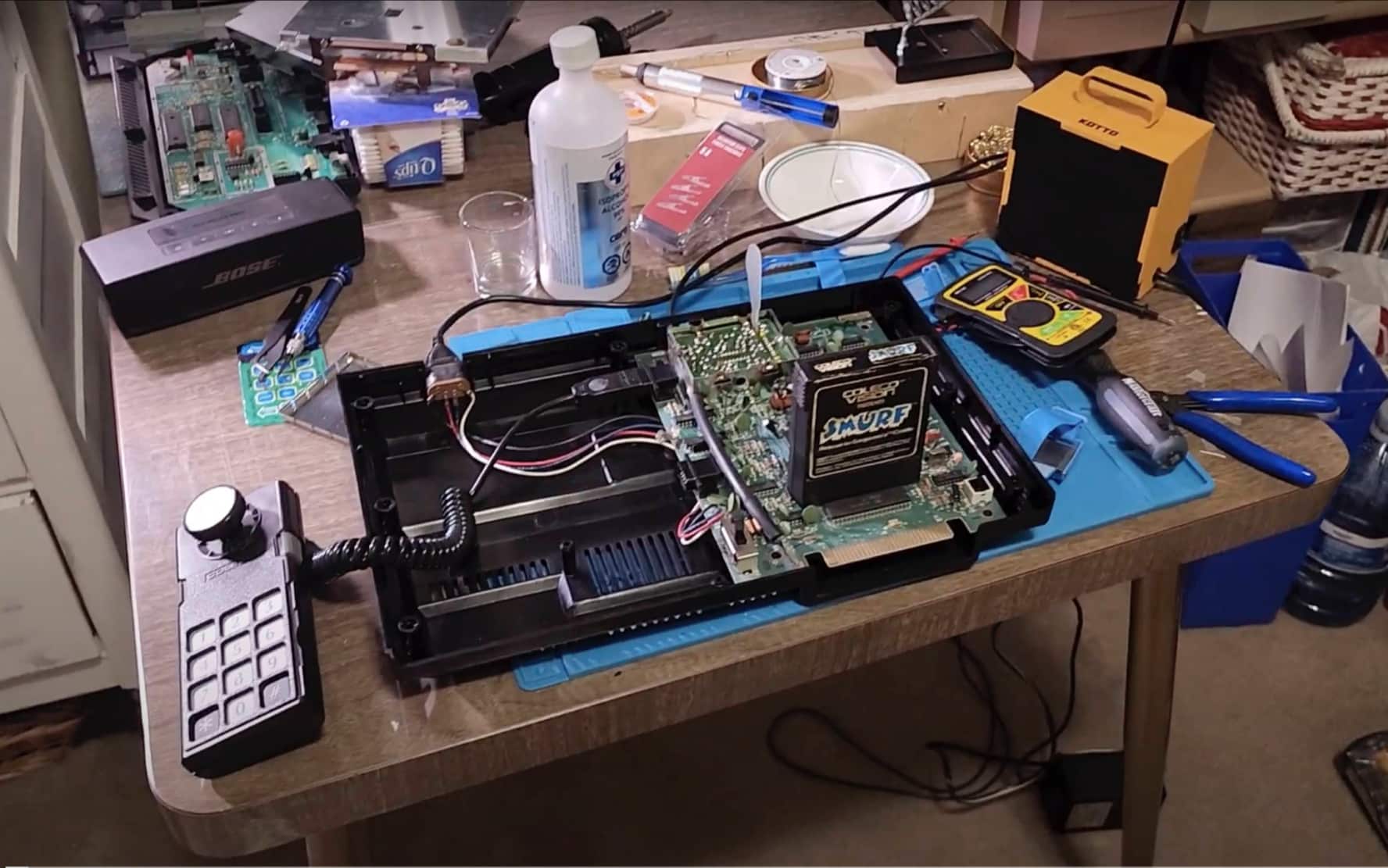


Project Details: I acquired this unit locally and it was partially functional. However, like the Astrocade, it came from a smoker’s home and before I could do anything, it and all its accessories had to spend several weeks sealed inside garbage bags with baking soda. When I opened the system up, I discovered it was quite dirty and there were two issues: 1) an occasional graphics glitch; and 2) an occasional sound issue where it would be fine and then suddenly shut off. After determining the power adapter was not the issue, I then desoldered and disassembled the power switch, cleaned the contacts, applied dielectric grease, reassembled, and soldered the switch back onto the board. Success! This fixed the graphics. I tackled the sound issue first by determining that it wasn’t a failing chip by connecting an external speaker via a jumper wire to ceramic capacitor C88. When I received rich and consistent sound without issue, I then zeroed in on the RF box and the audio subcarrier. Adjusting it with a homemade vinyl tool, I was able to get the sound back. However, if I squeezed the outside of the RF box the sound cutoff again, which told me there was a short somewhere. I reflowed a bunch of solder points and that seemed to fix it; however, if the issue arises again in the future, this unit may be a candidate for a composite mod. After testing the machine for quite a while and being satisfied with the results, I then cleaned it thoroughly. I also disassembled and cleaned the controller, the driving wheel, the track ball, and the Atari expansion unit. 😁
Parts & Products Used: 99% isopropyl alcohol; Chemical Guys Natural Shine; dielectric grease

ColecoVision (#2)
Years (1982 – 1985)
Interesting fact: The ColecoVision’s controller featured a 12 button keypad, fire buttons, and a direction joystick. Personally, I think the Atari 5200 controller is way more ergonomic and responsive than the ColecoVision’s. In September 1983, Coleco released the Super Action Controllers as an alternative that interestingly, featured force-feedback system in early prototypes, but which never made it to marker as part of the controllers. (source)
Condition When Acquired: Non-Functional (DOA)
Current Condition: Fully Functional


Project Details: This unit came to me DOA. An initial test of the power adapter indicated that it was putting out the correct +5v and -5v, but not the necessary 12v. It was only showing 11.75v, which was in tolerance for spec but lower than I liked. I powered the unit on, but could not get anything but static. To cover my bases, I tried another power adapter that I knew was outputting the required voltage and powered the unit on. Progress! A snowy and flickering image came onto my TV. I got the game started and I could also hear audio, so this was also encouraging. I adjusted the tuning on the RF box and was able to generate a stable image and sound. For good measure I also desoldered, disassembled, cleaned, reassembled, and solder the power switch back into place. The system now worked like it was supposed to. I turned my attention to the controllers as one did not work and one had limited movement. After taking them both apart, I discovered that the non-working controller’s board had been broken in half at some point and somebody had run wire hacks to compensate. I tried to fix it, but it was too far gone, so I found a couple Coleco Adam controllers online and ordered these in to harvest for parts. Continuity tests on the other controller discovered a broken trace that I was able to fix with my own wire hack. I performed a detailed cleaning of the controller and the main console. The unit works now works great, but only has one controller.
Parts & Products Used: 99% isopropyl alcohol; Chemical Guys Natural Shine; dielectric grease; replacement Colecovision power adapter; 22 gauge wire

ColecoVision (#3)
Years (1982 – 1985)
Interesting fact: The ColecoVision’s Expansion Module #2 was a steering wheel unit that came packaged with the game Turbo. At the time, it was the most advanced peripheral device available for a console. (source)
Condition When Acquired: Partially Functional – graphics glitching and no sound
Current Condition: Fully Functional


Project Details: Like ColecoVision #1, this unit came to me with graphics and sound issues which meant that I proceeded the same way as the units above. It also meant that it came at a really good price. 🙂 After determining the power adapter was not the issue, I then desoldered and disassembled the power switch, cleaned the contacts, applied dielectric grease, reassembled, and soldered the switch back onto the board. This fixed the graphics issues. Before checking the c88 capacitor, I adjusted the audio subcarrier and the sound came back – and more importantly, stayed that way. I then pulled apart and cleaned the controllers along with the entire console. The unit now works as it should.
Parts & Products Used: 99% isopropyl alcohol; Chemical Guys Natural Shine; dielectric grease;
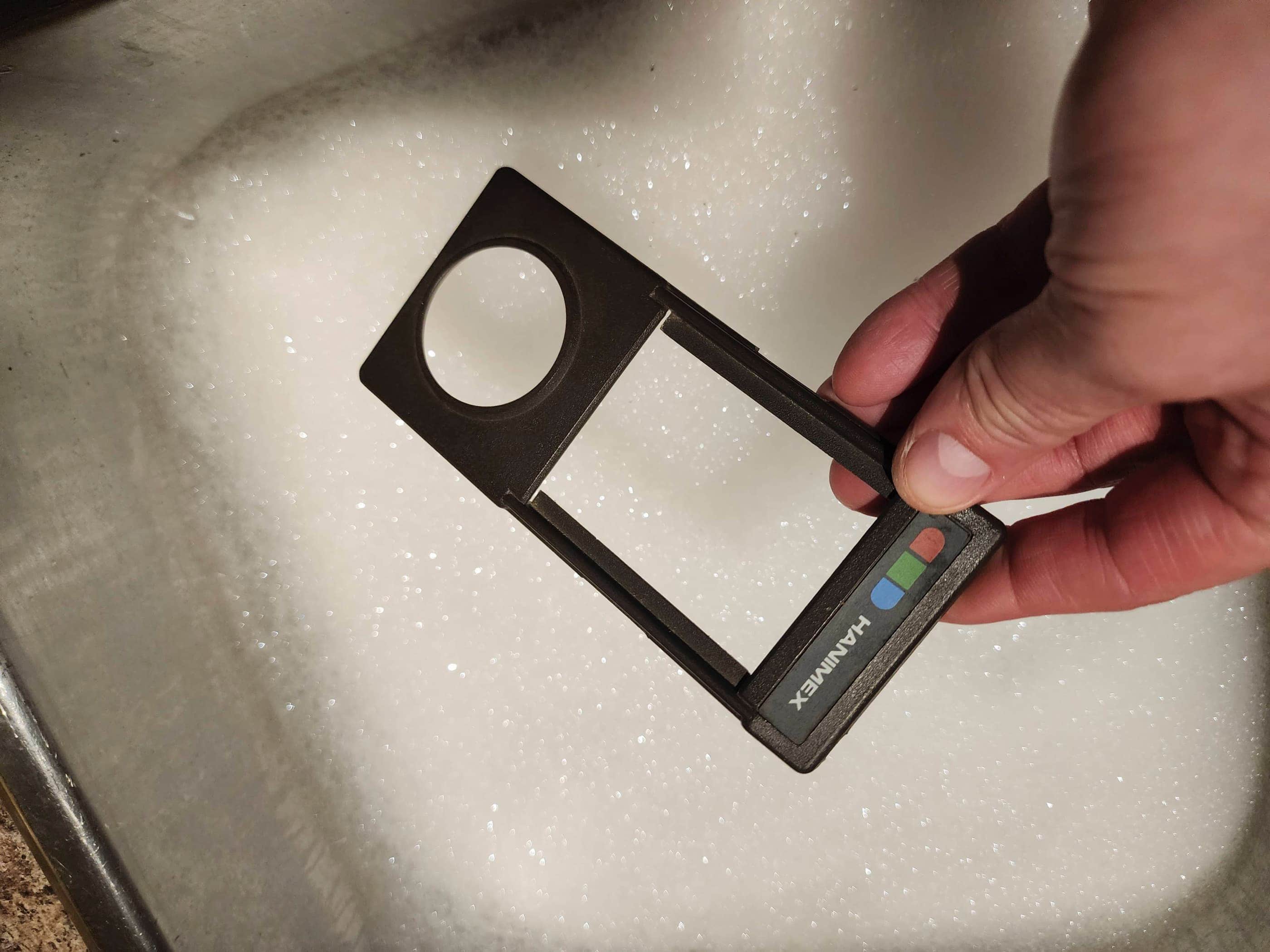
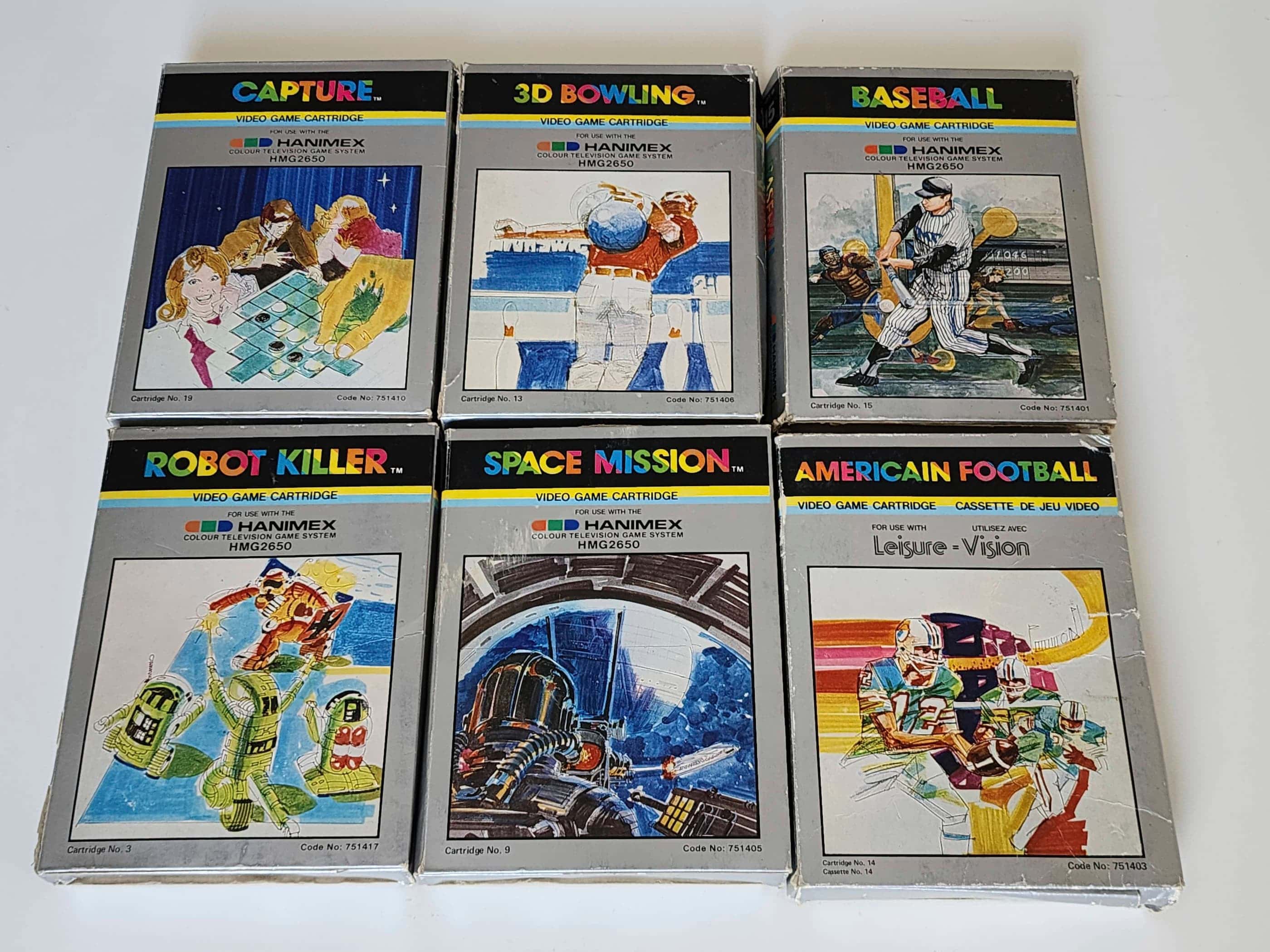
Hanimex HMG 2650
Years (1982-1984)
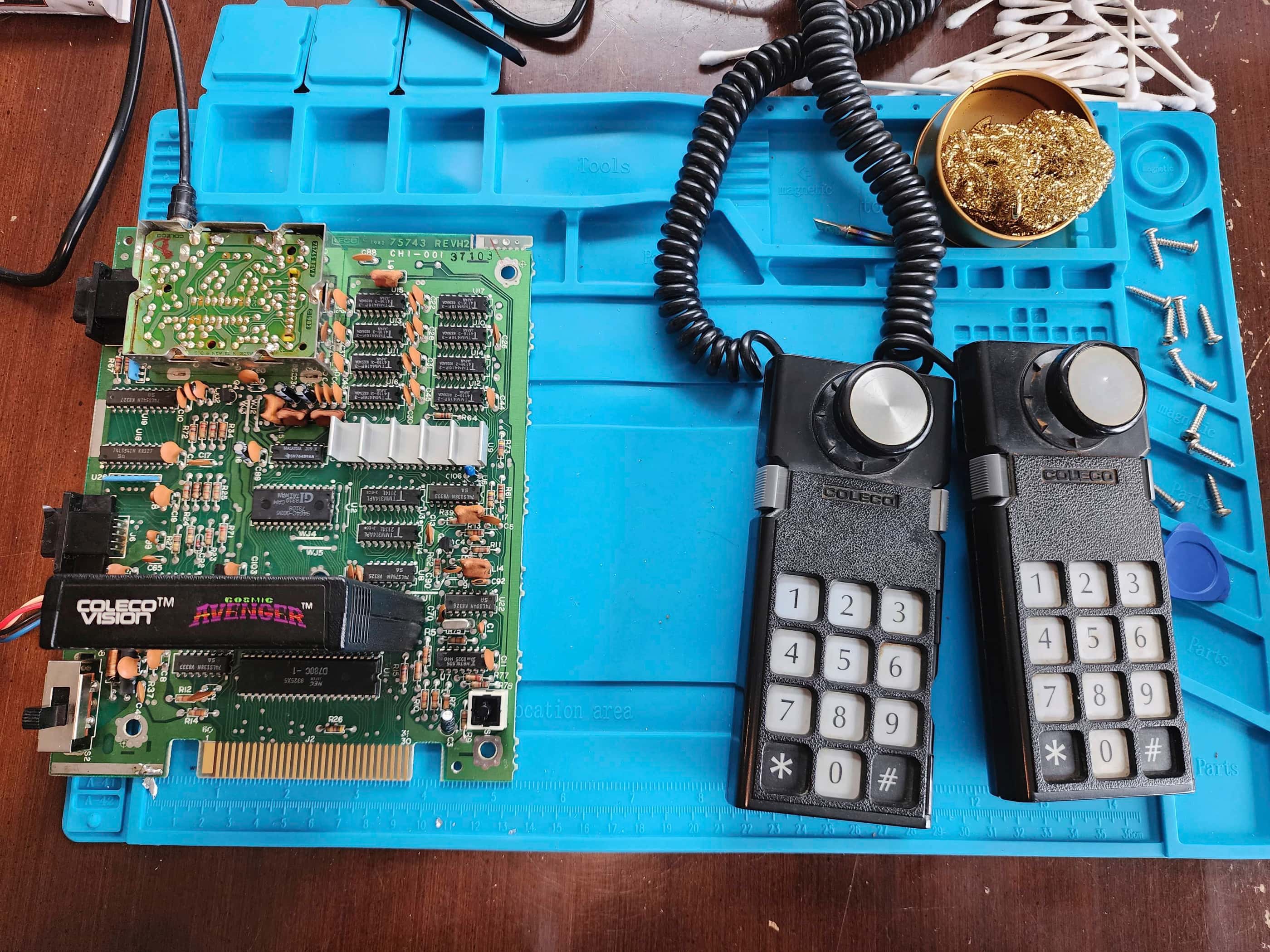
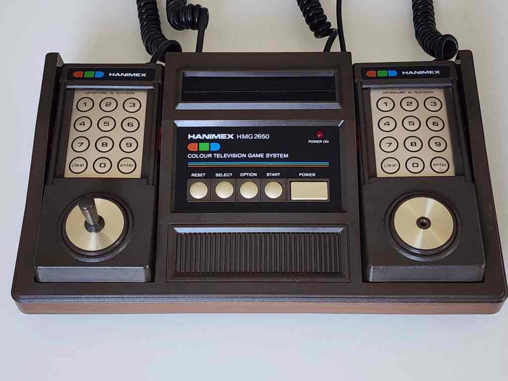
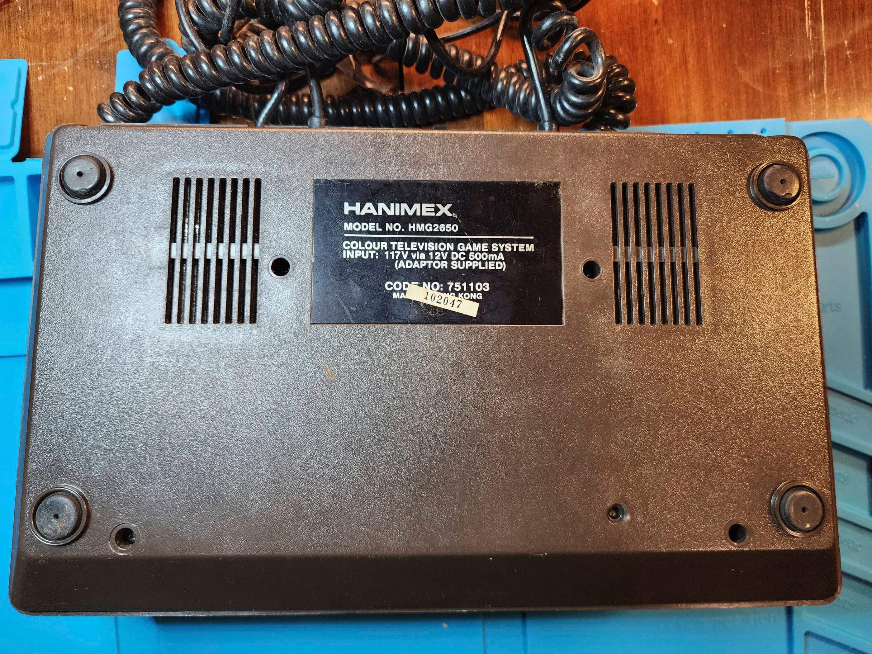
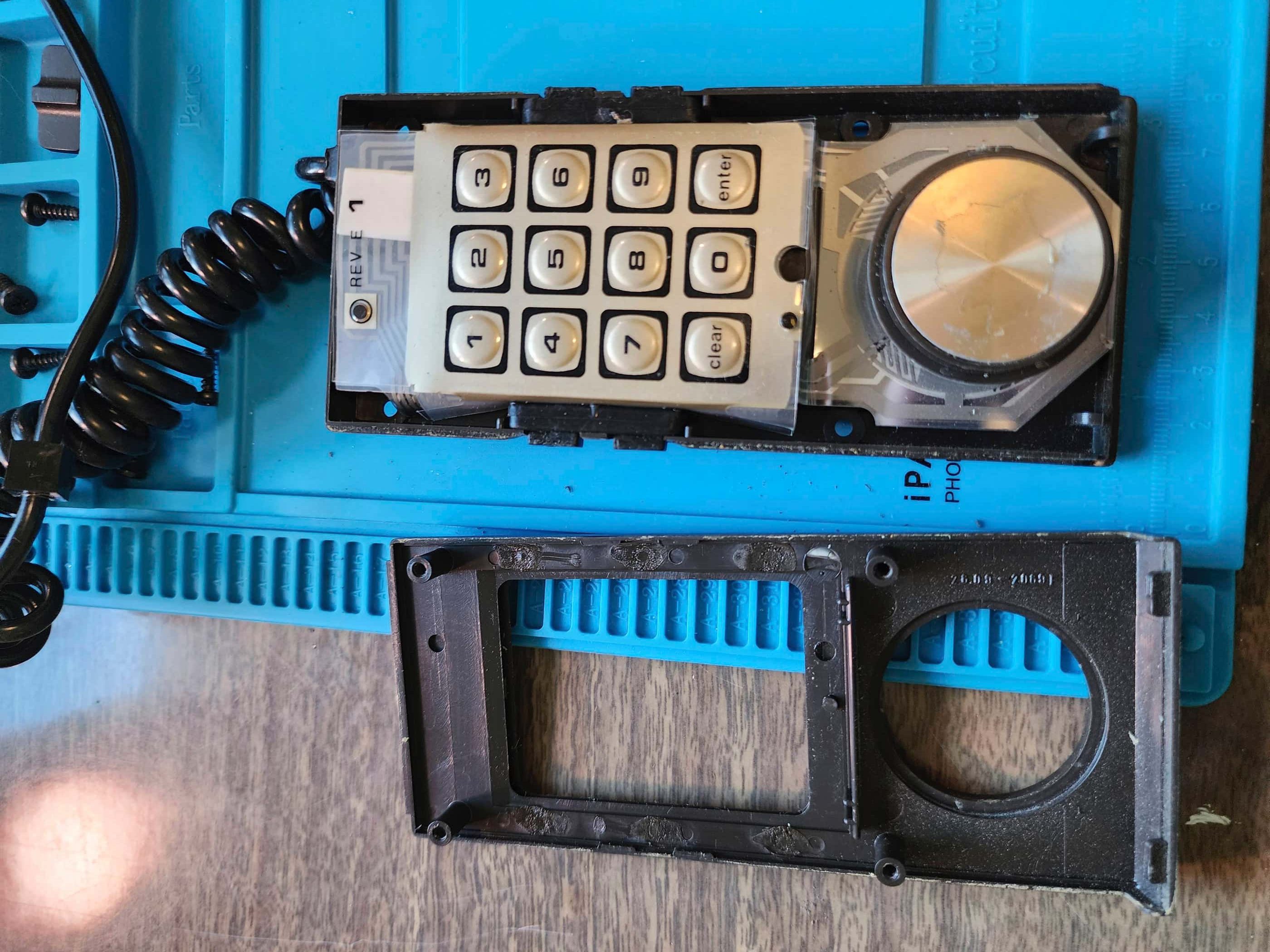
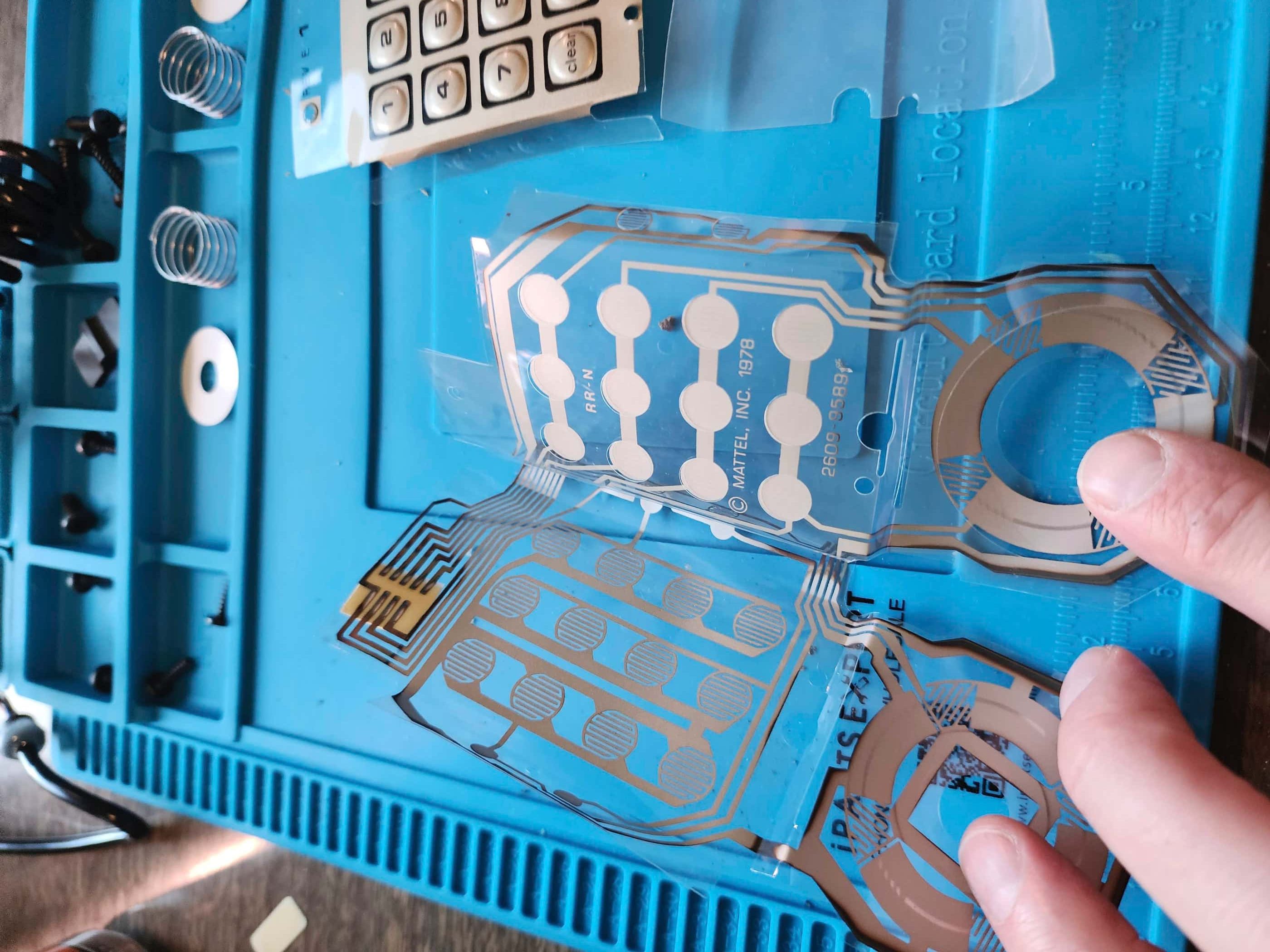
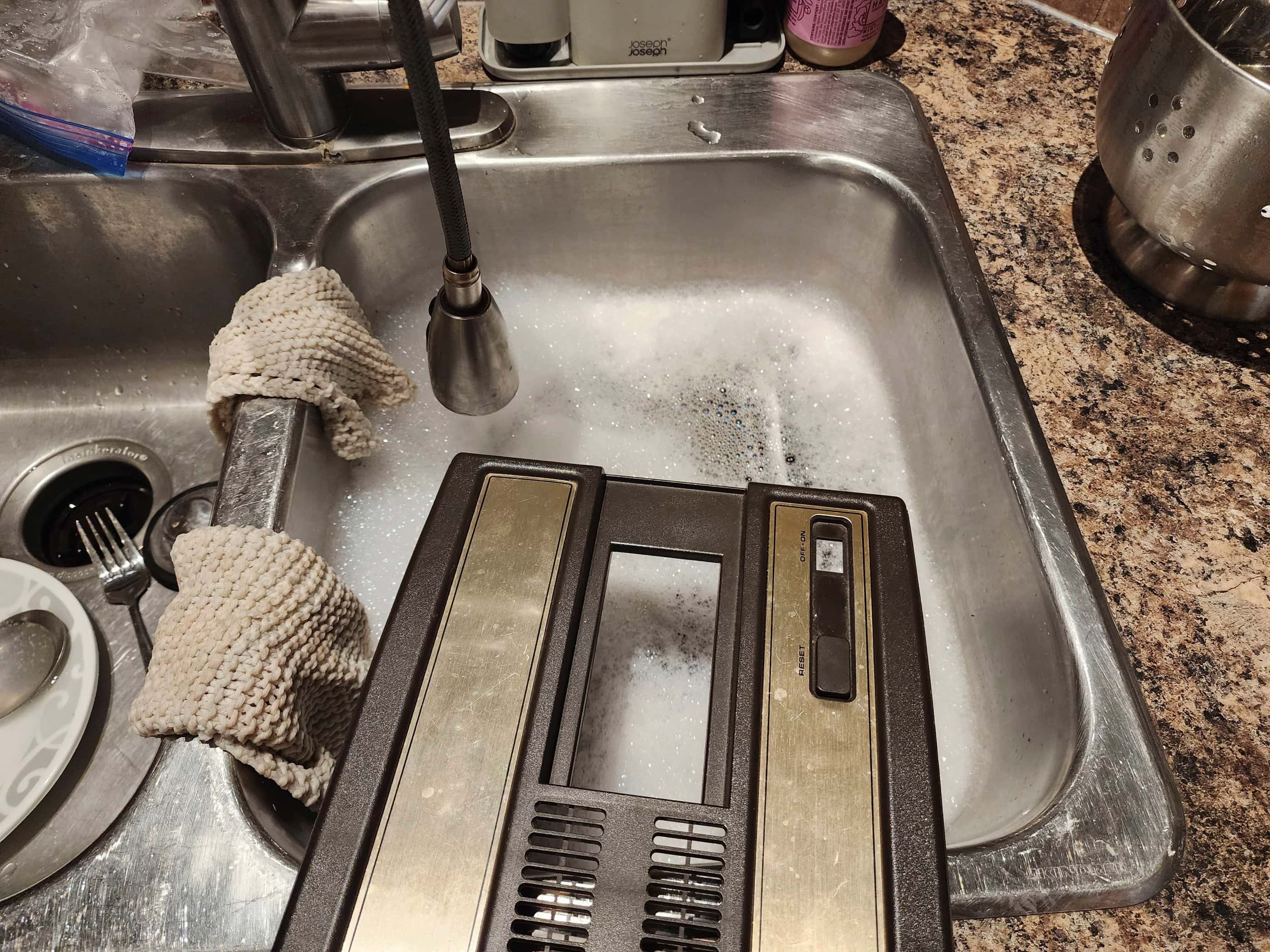
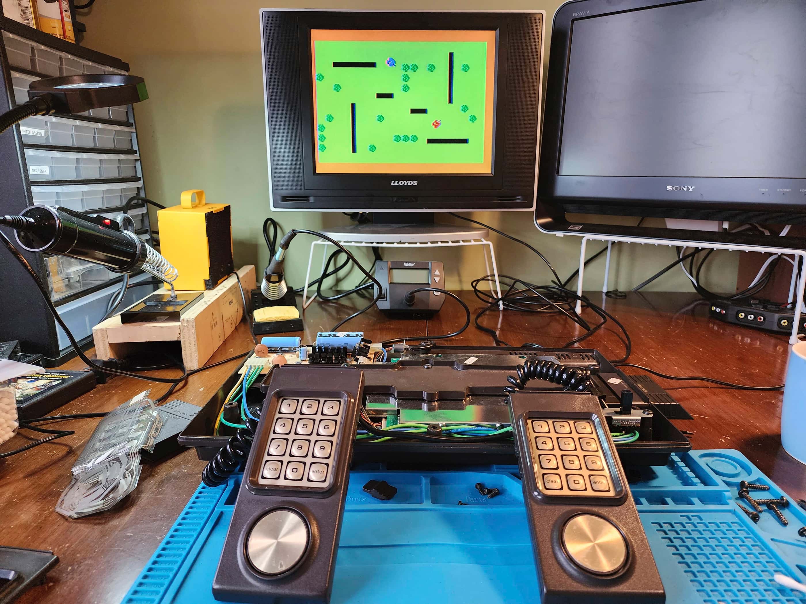
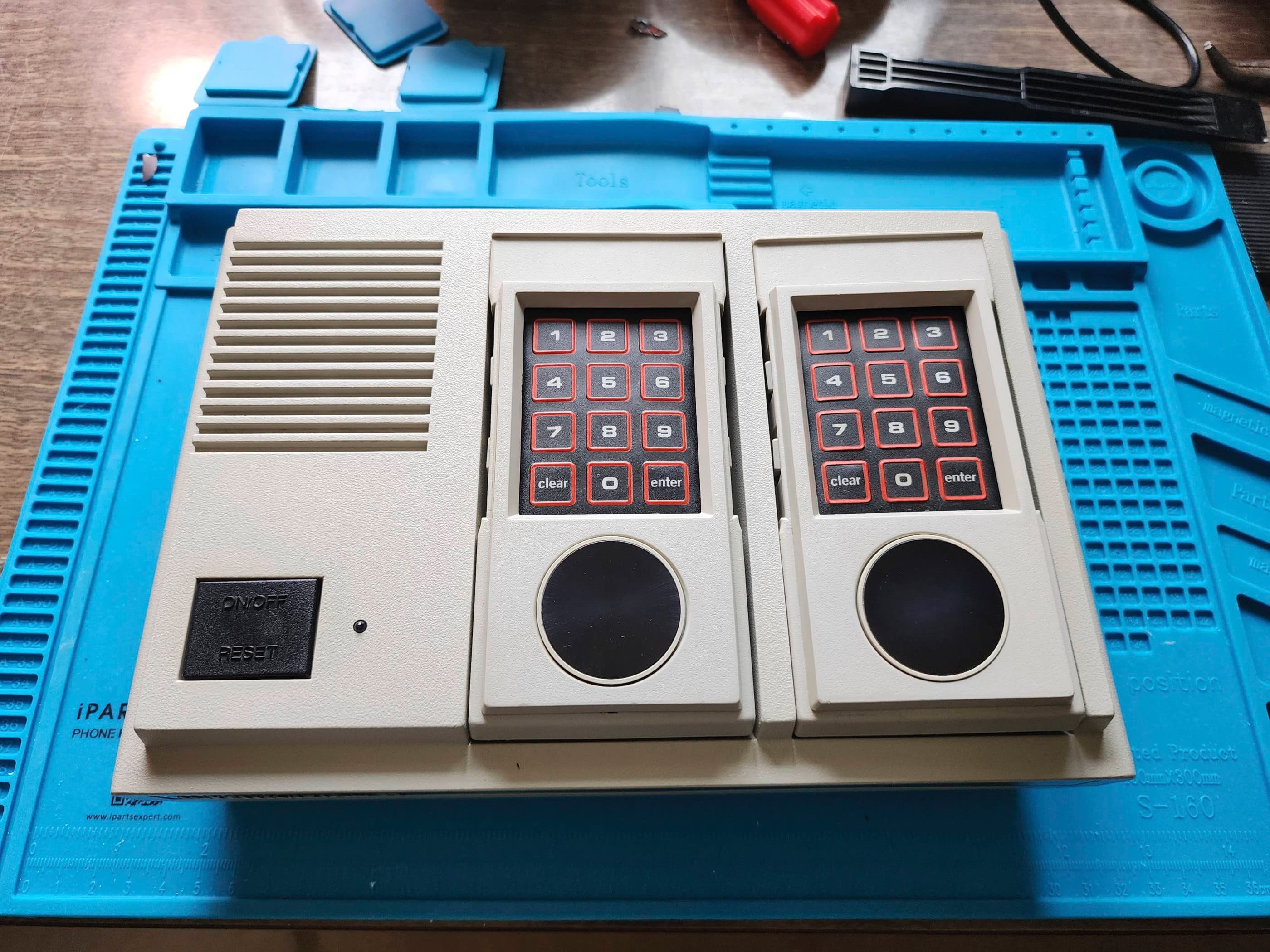
Interesting Fact: The Hanimex HMG 2650 is one of several international versions of the Emerson Arcadia 2001. Developed in Hong Kong in 1982 by United Appliances Limited, the console was licensed to Emerson for use in the United States and also to Hanimex, an Australian company, for international use including, Canada. (source) It was also licensed to numerous other companies and depending on the region, the console can have a different name. For example, it was licensed to the Canadian Company, Leisure Dynamics, and was released only in Canada as the Leisure Vision console. (source) This means that in 1982, Canadians had the option to buy the same console (and cartridges), but under two different brand and console names. Designed to dethrone the Atari 2600, the HMG 2650 / Arcadia 2001 did not last long, as it had no third-party support and the newly released ColecoVision and the Atari 5200 were vastly superior machines. (source) The HMG 2650 is named for the Signetics 2650 8-bit microprocessor that it used. Interestingly, the system cloned the original Intellivision controllers, but made a few small changes such as: the addition of a small joystick; the inclusion of only one fire button on each side; 11-pin connectors instead of 9; and the limitation of the control pad to 8 directions.
Condition When Acquired: Non-Functional
Current Condition: Fully Functional

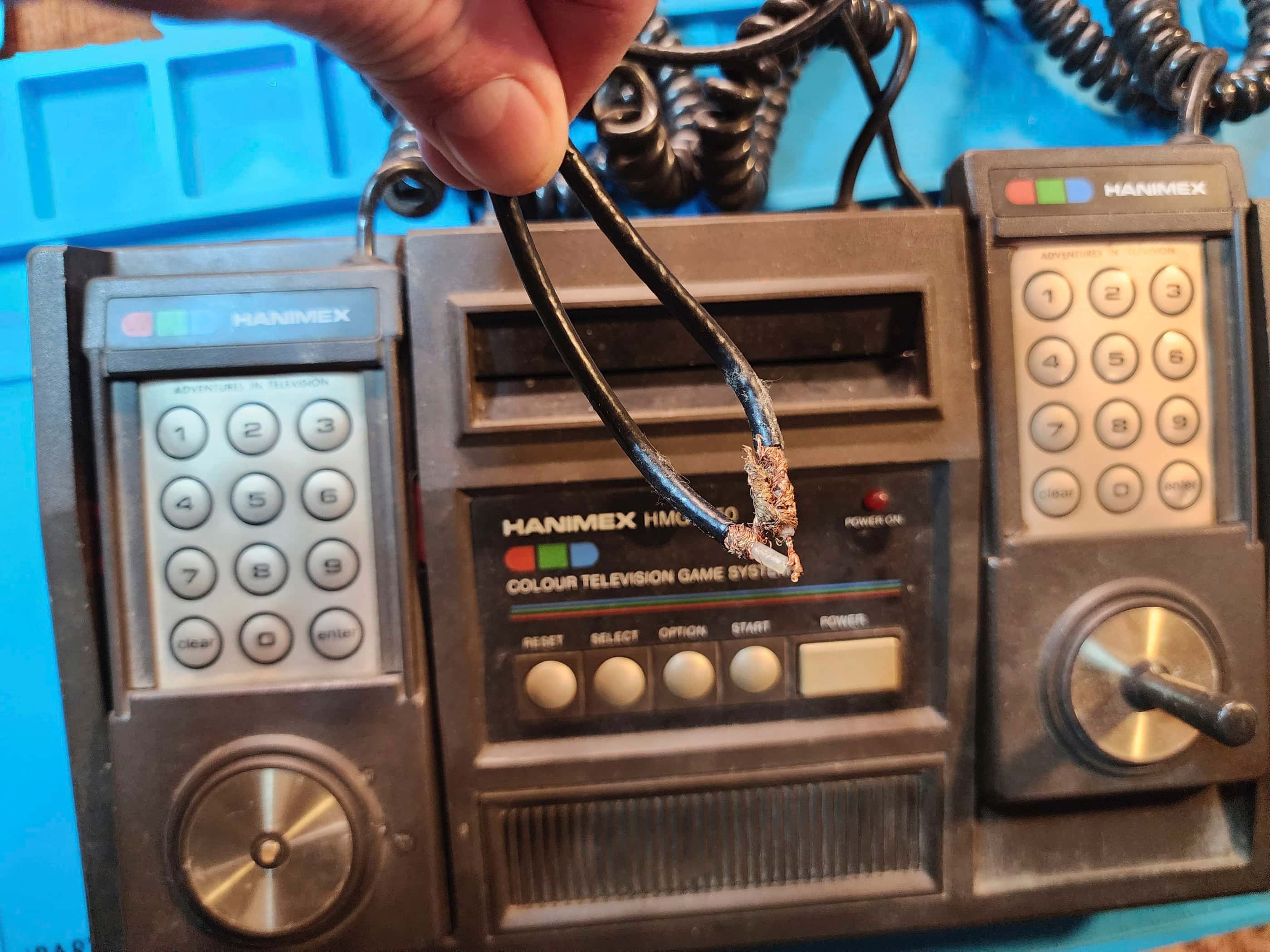


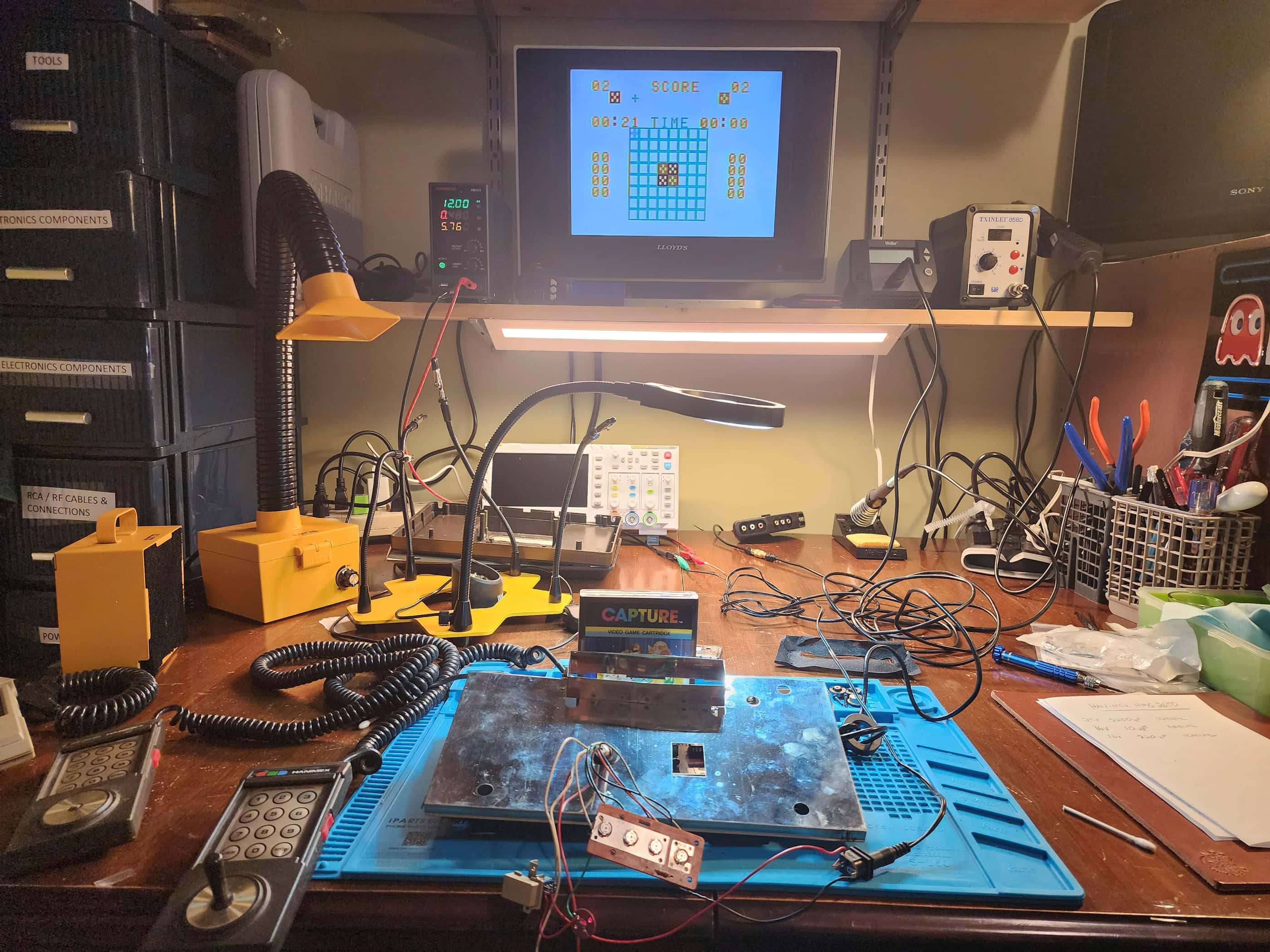


Project Details: I first saw this unit almost a year ago when my local retro game store, Blast From The Past, had someone drop it off. Sporting an obvious cut and attempted repair on its RF cord, both the owner and I were unsure if it worked. Fast forward to this month, and I happened to be in the store, and sure enough, it was still sitting on the floor behind a display case – and it was still untested. The owner gave me a good deal on the console along with a few games, and I was excited to get it home and get to work. 🙂
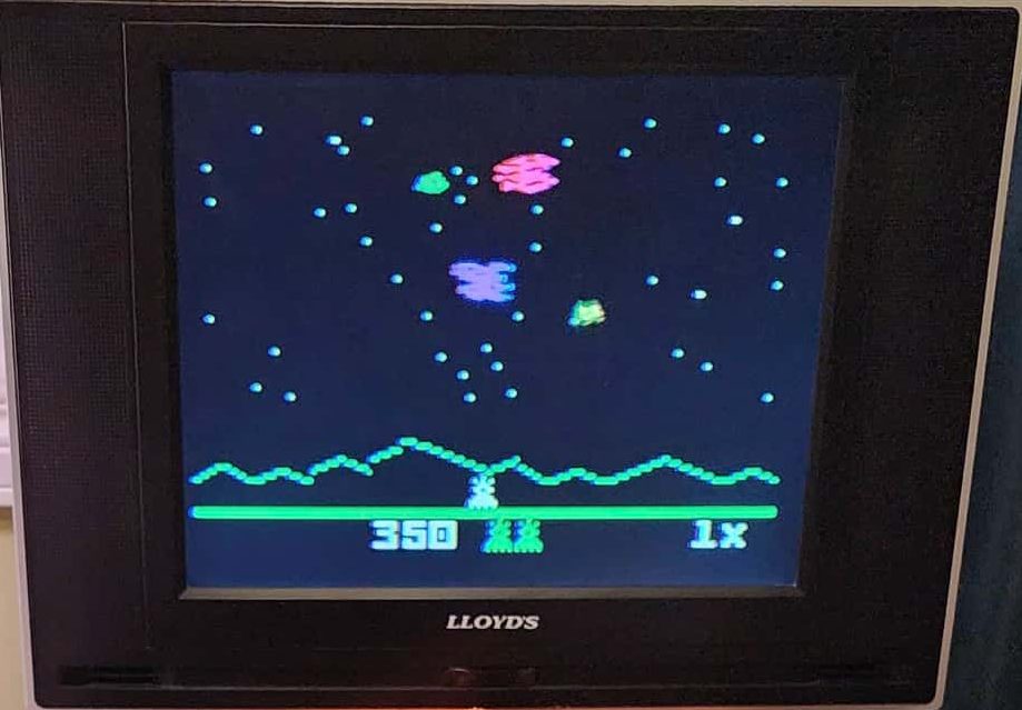
As it did not come with a 12v 500mA power adapter, the first thing I had to do was figure out if the barrel connector needed to be centre-positive or centre-negative. Messing this up would be disastrous, so I made a quick online search and confirmed that the Arcadia 2001 was centre-positive, so I ventured this must be as well… I then hooked up my bench supply and tried out some cartridges. As I suspected, the RF cable was botched, so I made a quick solder repair and a few minutes later, tried another game. I was happy to see garbled graphics on the screen which meant that the system had at least some life in it.
I then cleaned the cartridge slot and the cartridge and then fiddled a bit more with the RF cable. I tried it again and I the game appeared on the screen. Nice! 😁 I now had even more hope, and I set to work opening the console so I could replace the RF cable along with anything else that might need it.
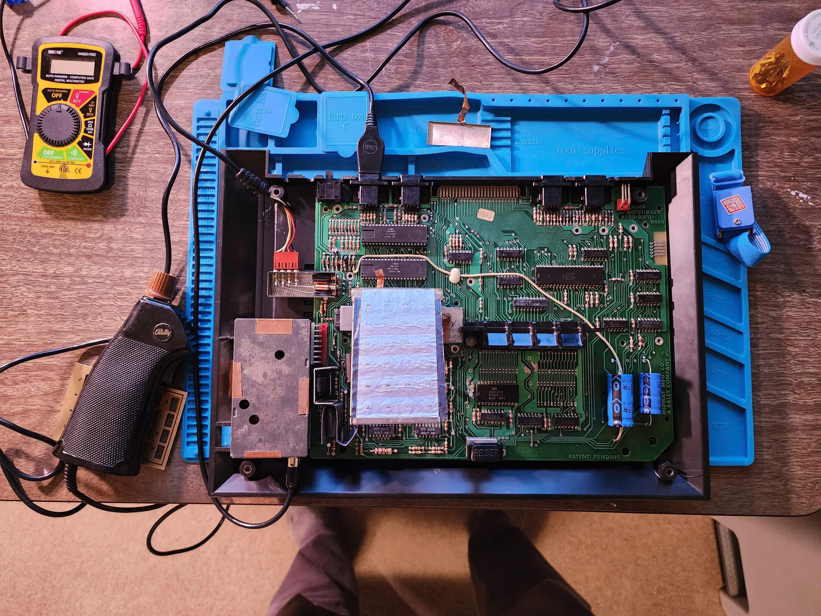
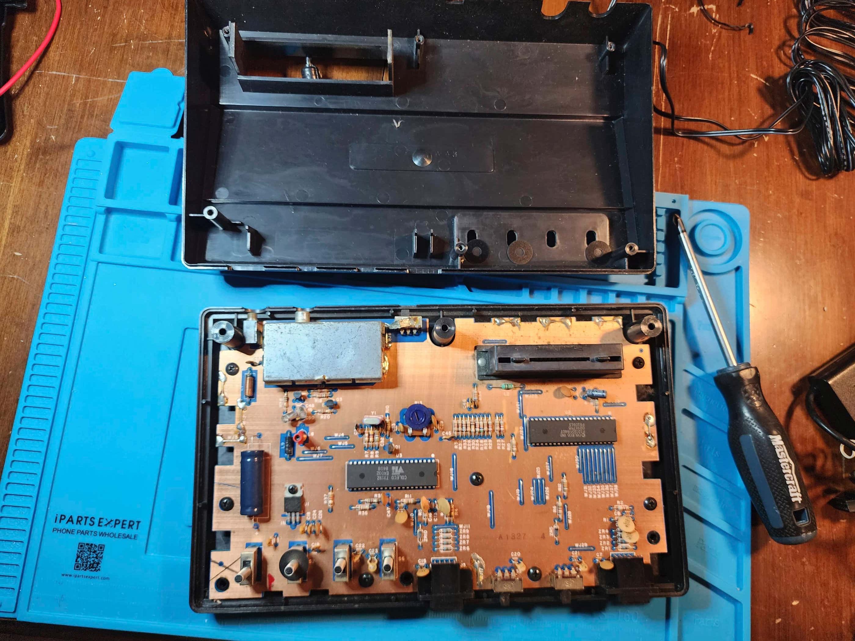
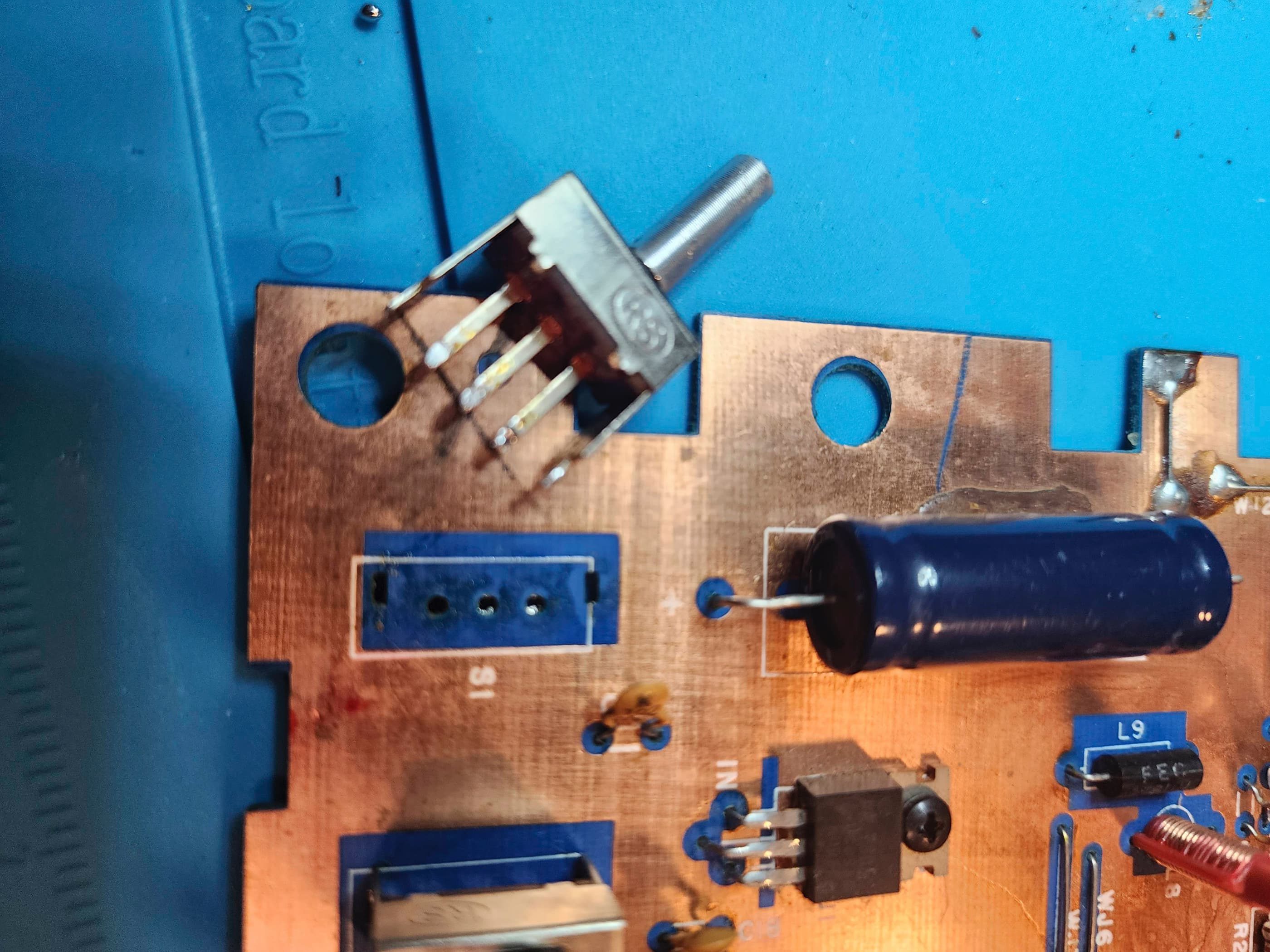
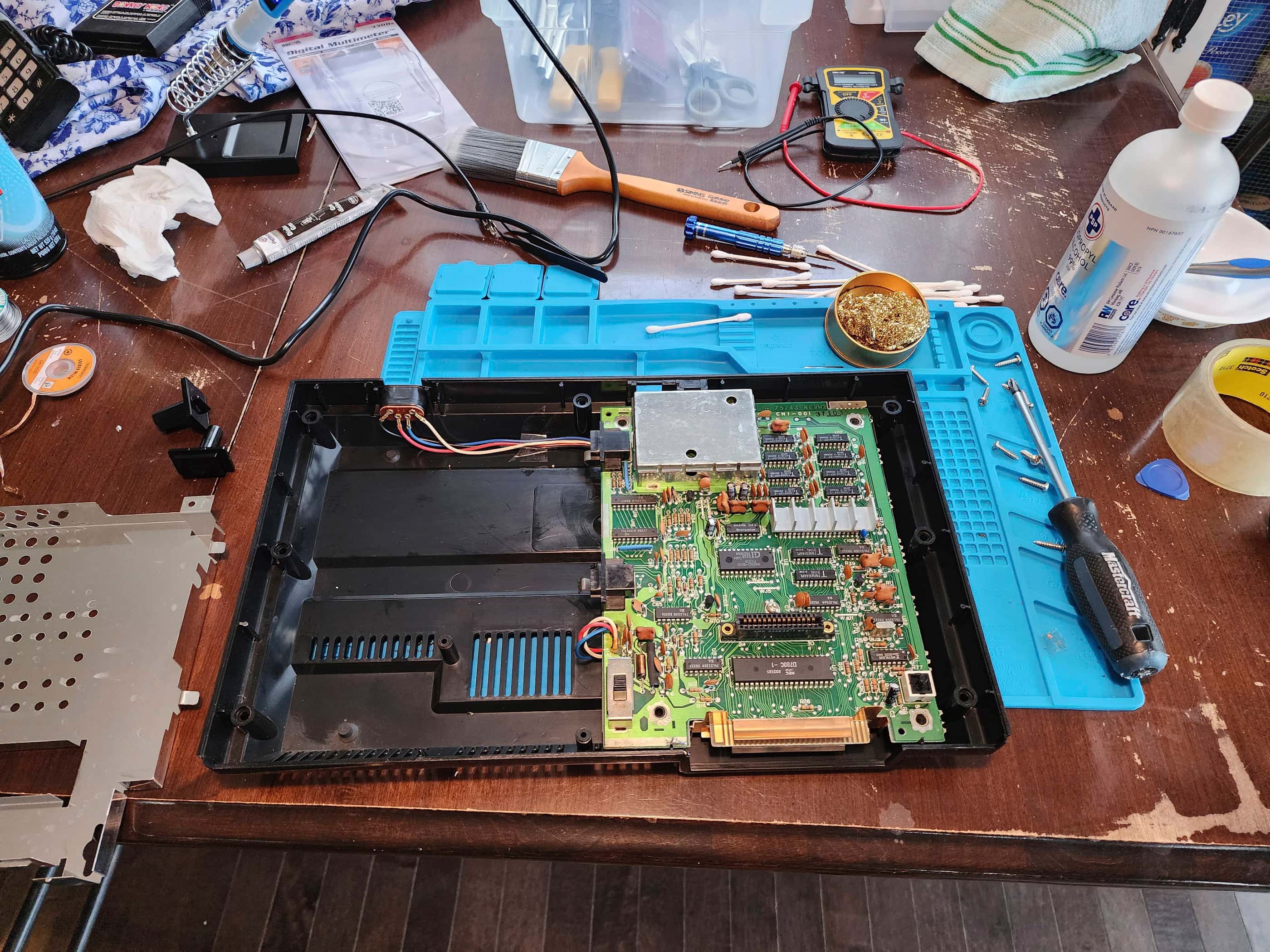
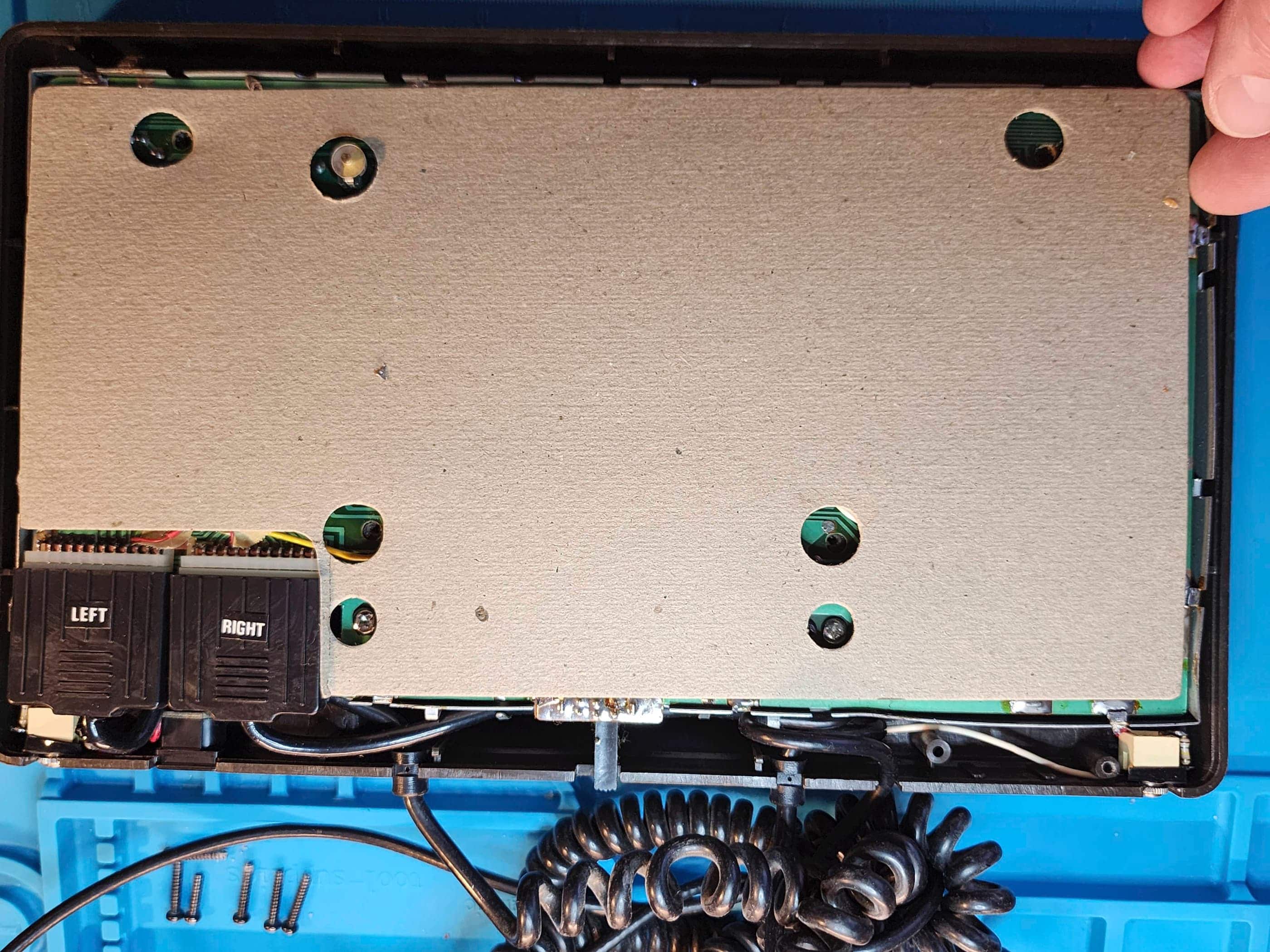
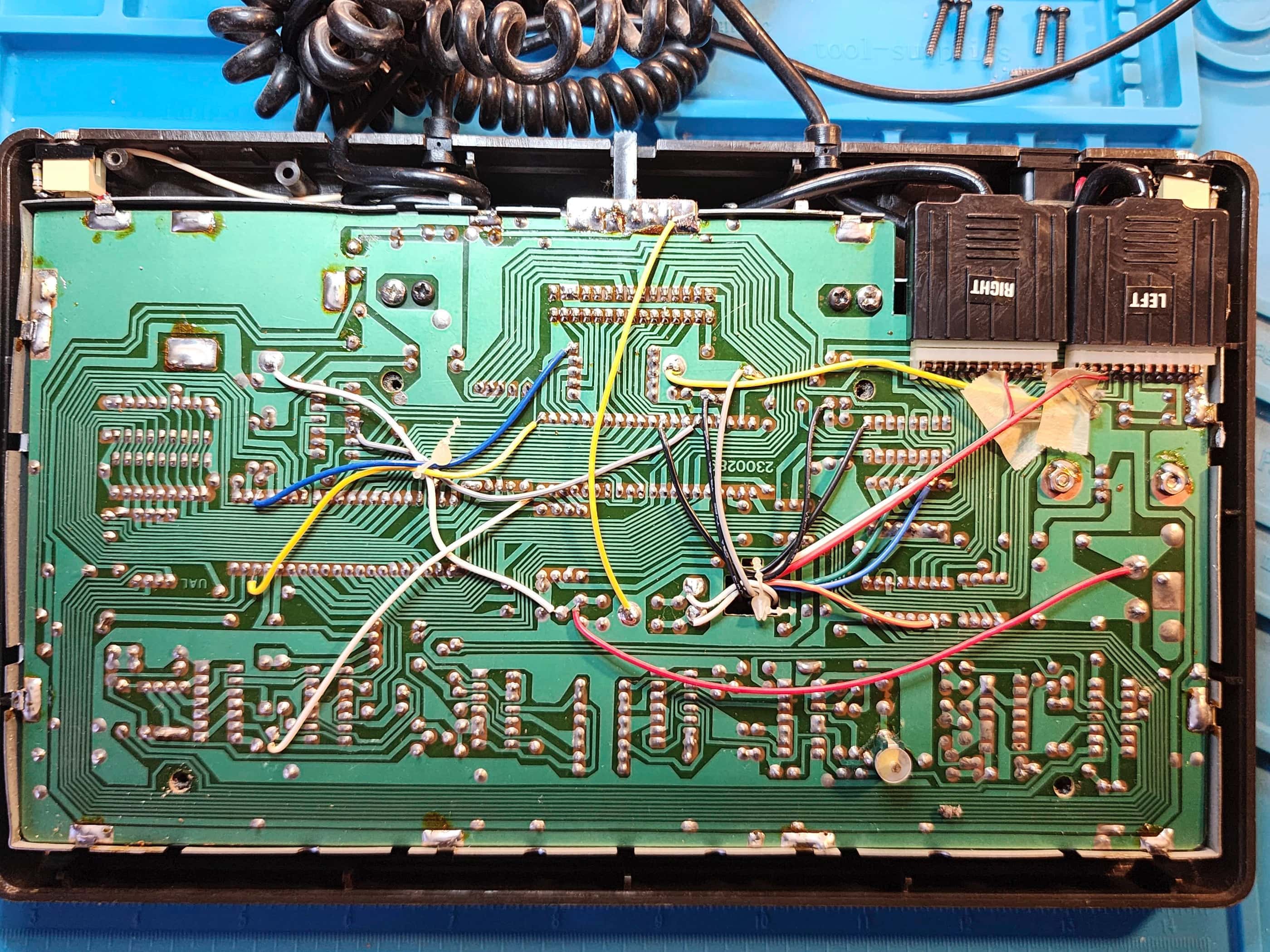
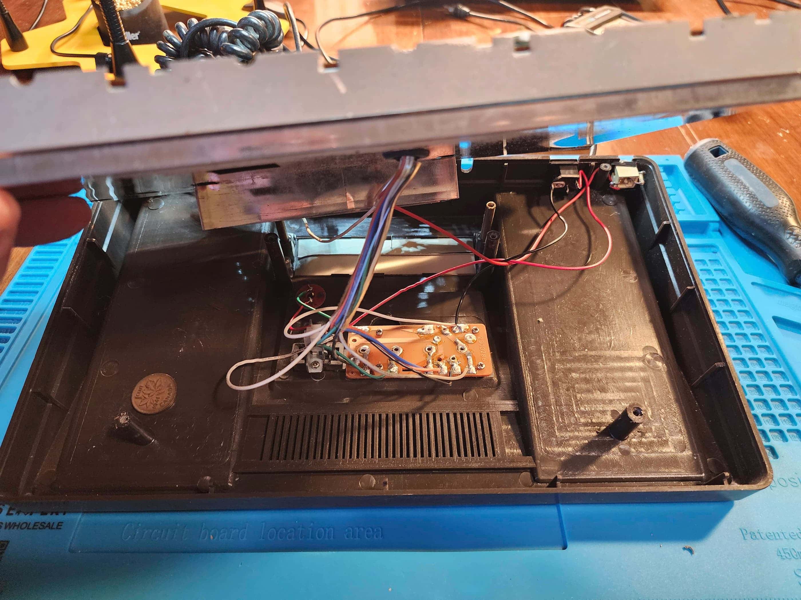
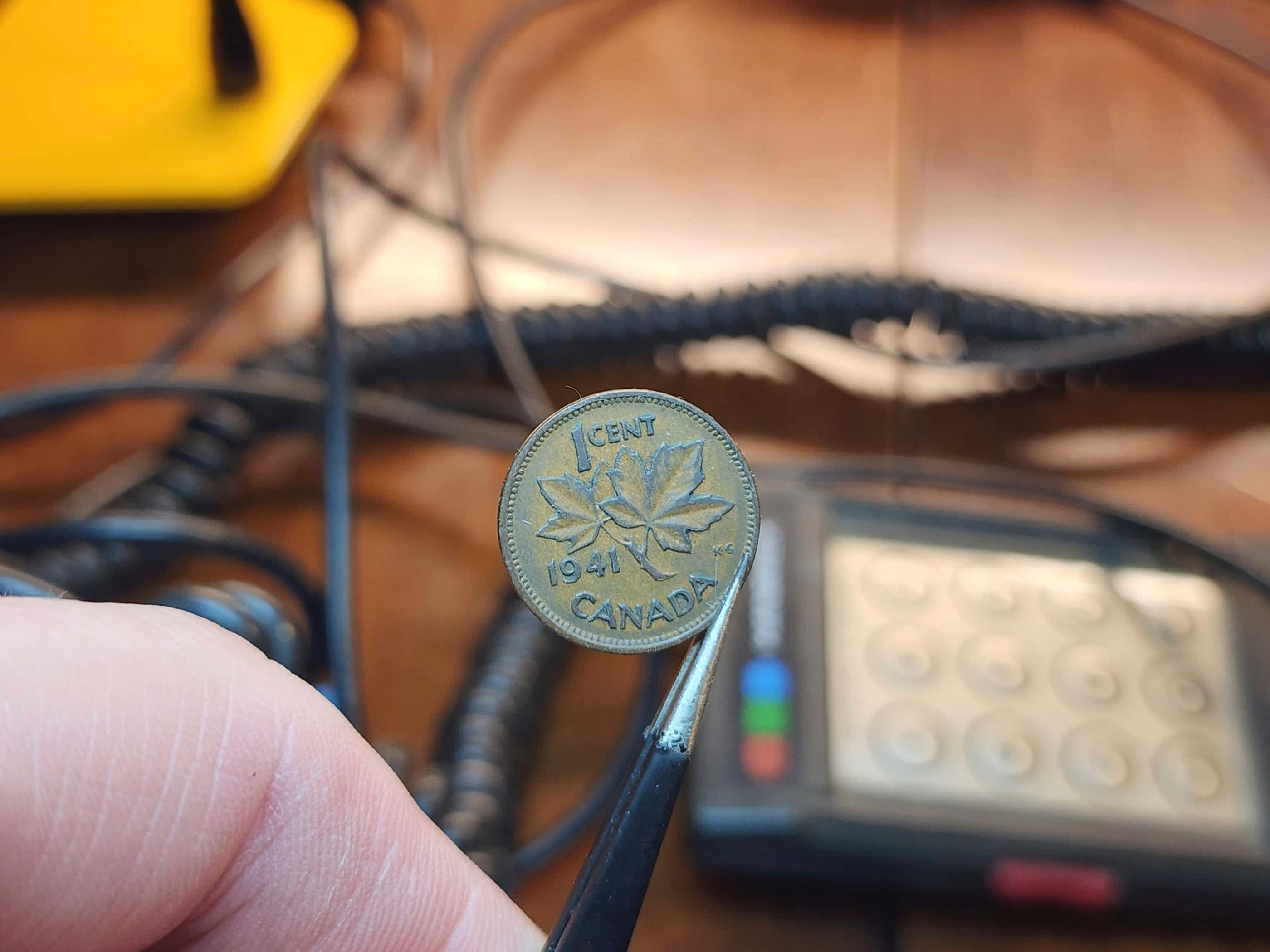
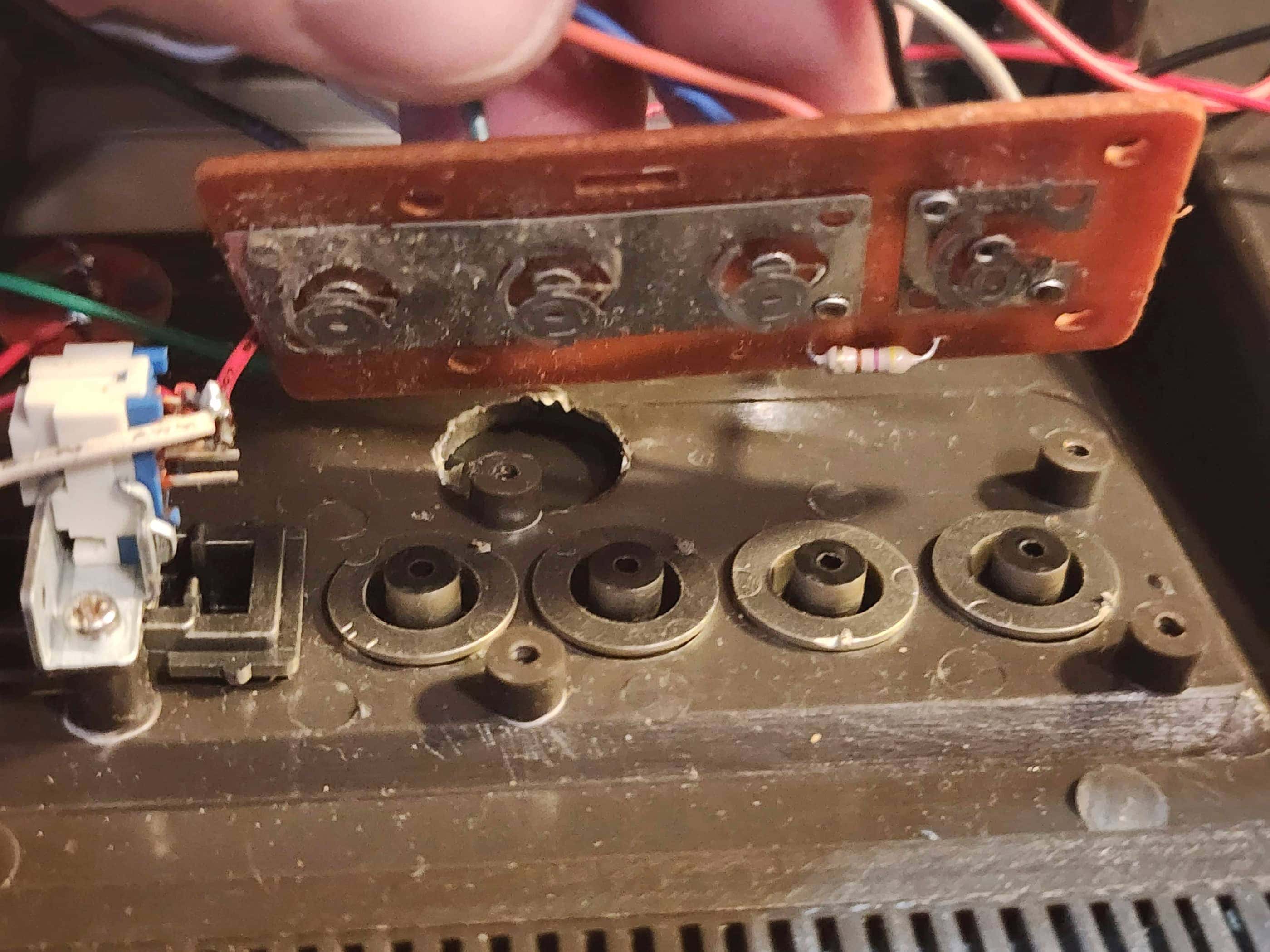
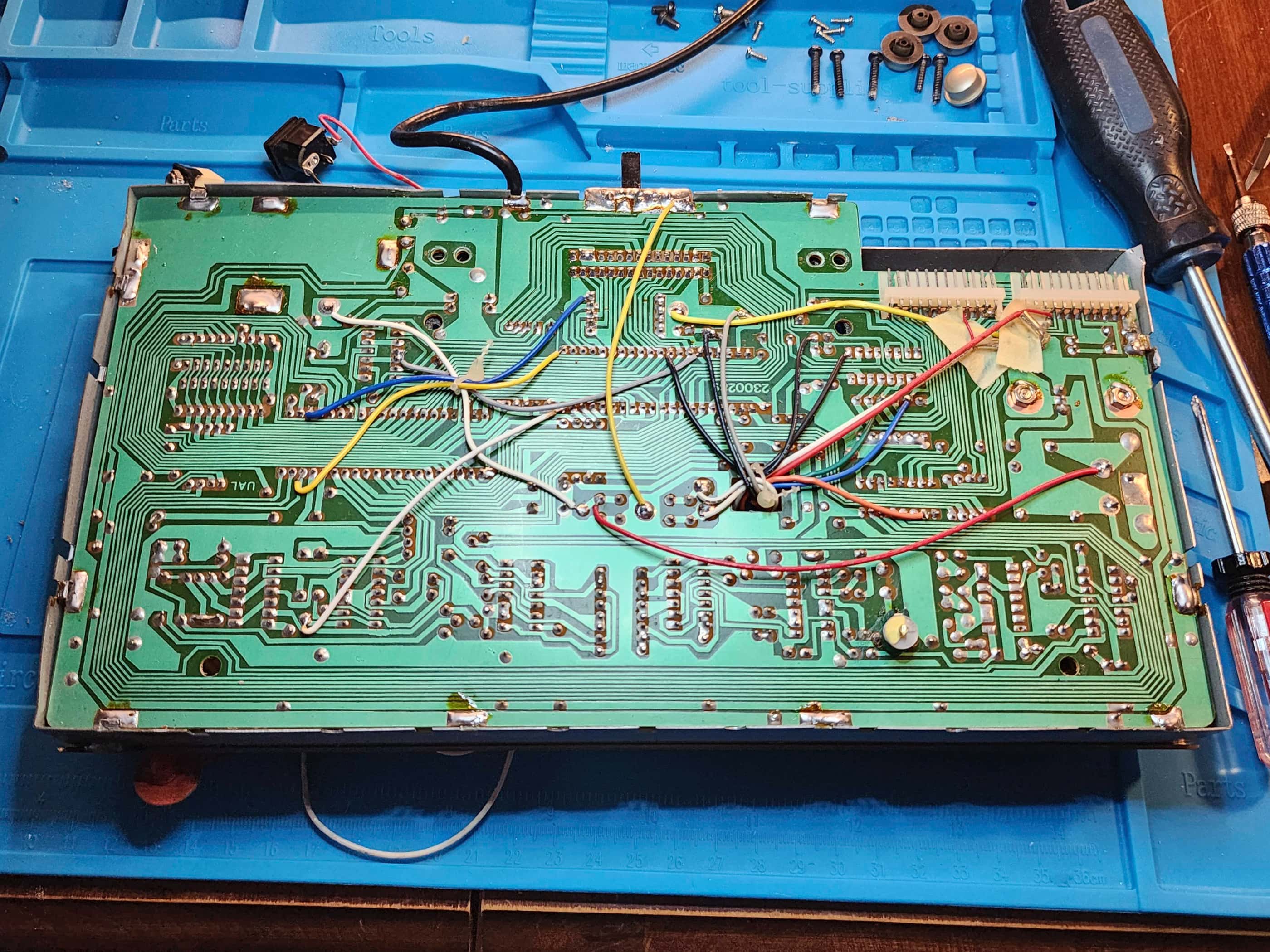
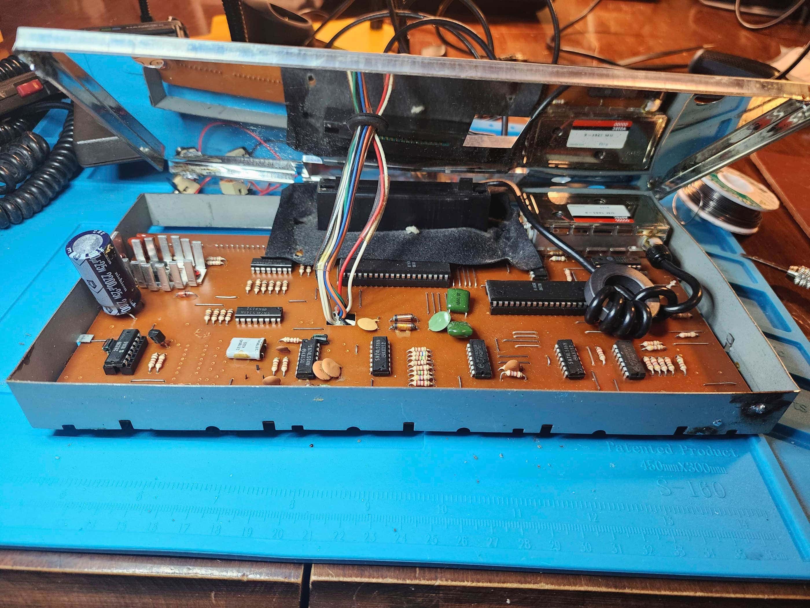
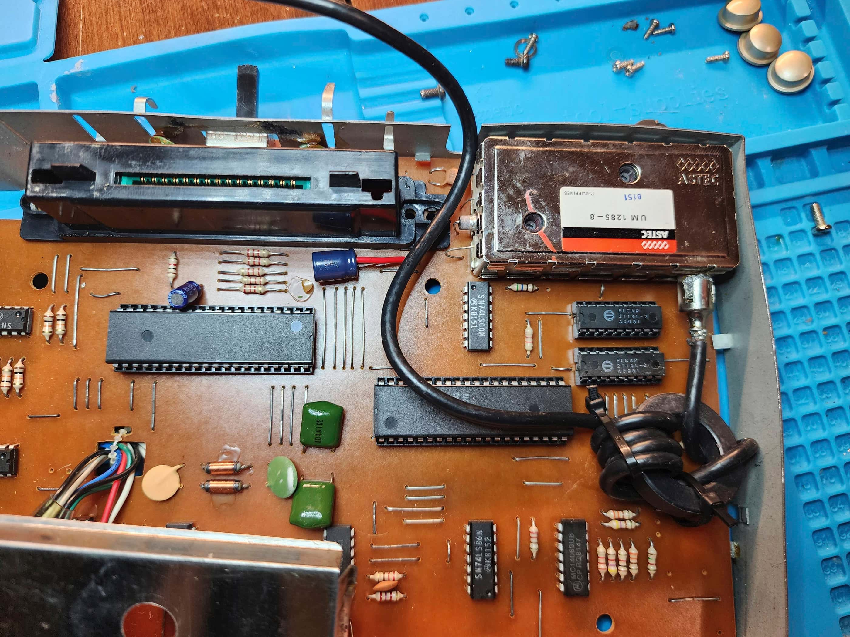
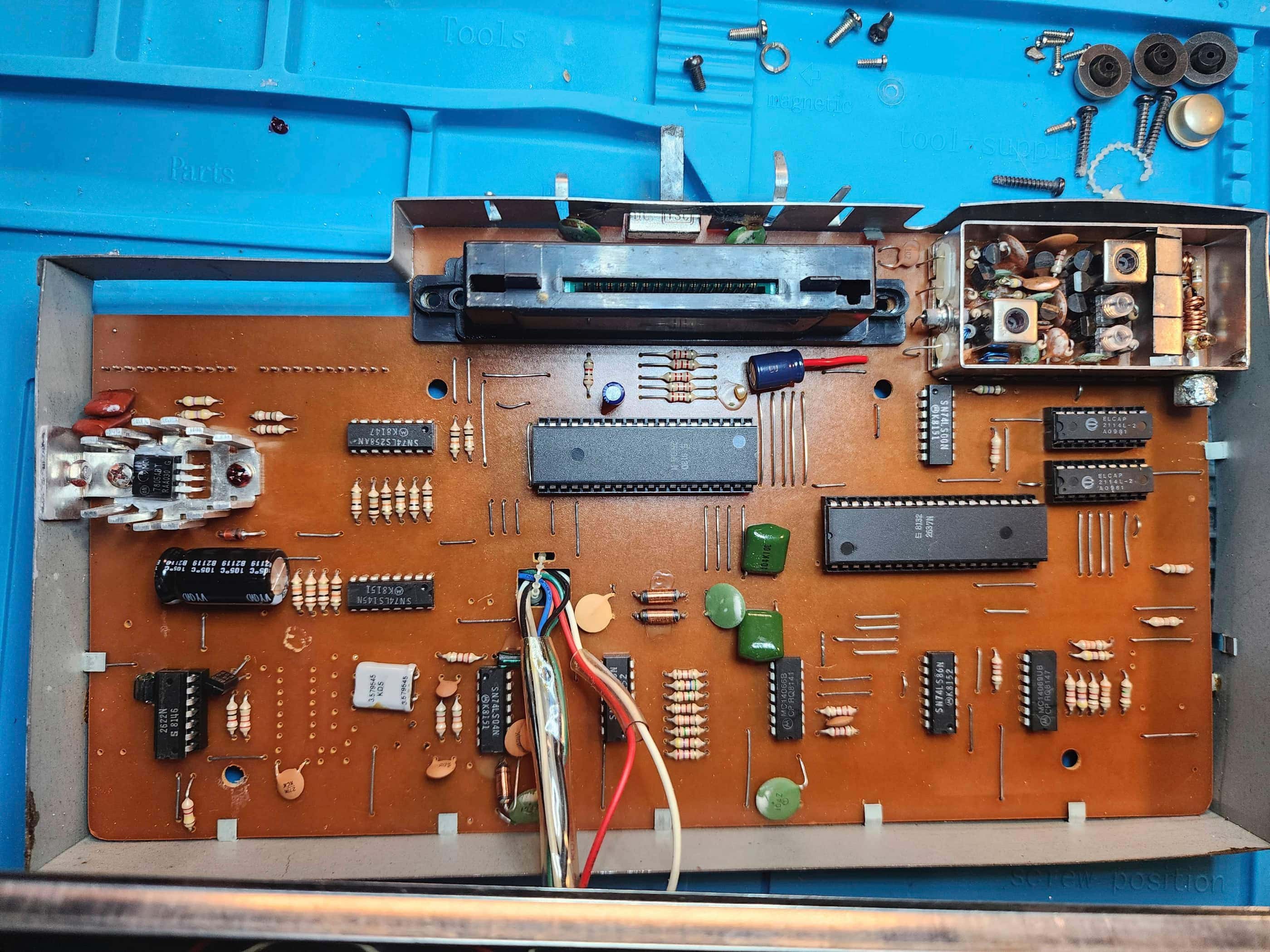
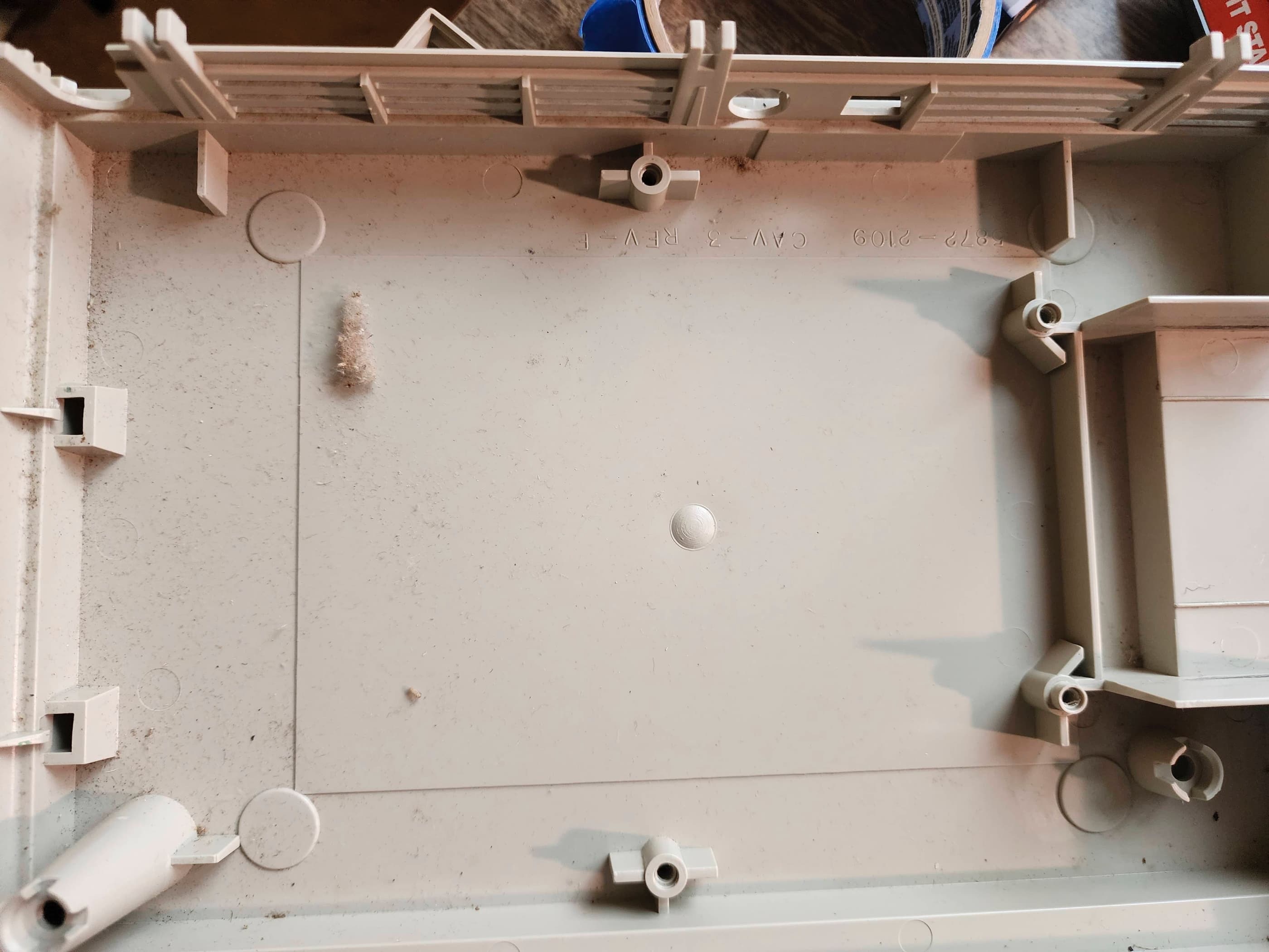
I was surprised by a few things that I found inside. The first was a Canadian penny from 1941. I know its old tech, but I didn’t think it was that old! 😂 It must’ve dropped into the cartridge slot back in the day where it luckily found a home between some plastic and the RF shielding, because otherwise, it would have shorted the system. The second item was a dead bug, which I guess wasn’t surprising, but I’m always shocked when I do find them. The third thing was all of the jumper wires that were used on the board and between the board and the panel buttons. There was a crazy number and the fact they had little-to-no slack, made working with them difficult. That they were fed through a hole in the RF shielding made it even more difficult to work with. Finally, the other thing that surprised me was the lack of labels on the PCB. Nothing was labelled and up to this point, I’d never see this before.
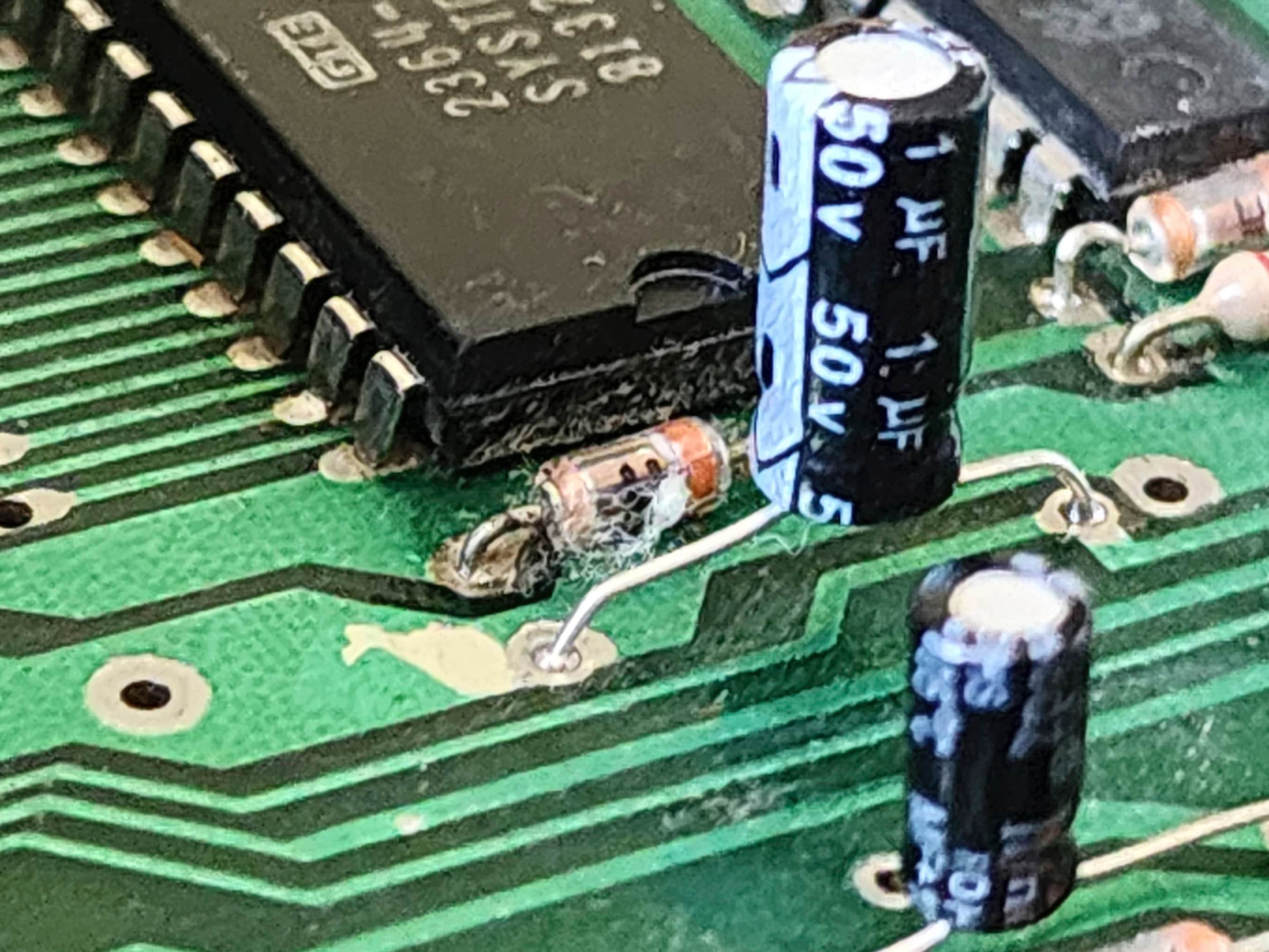
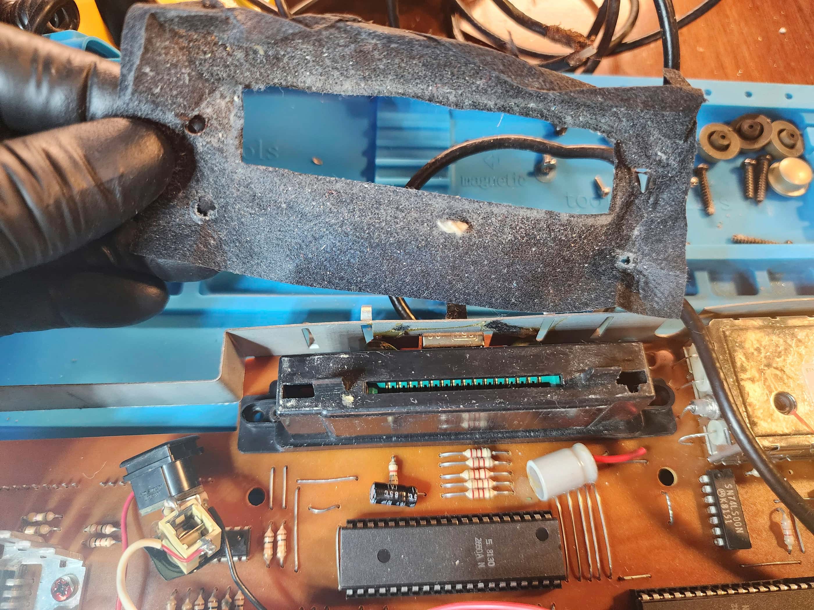
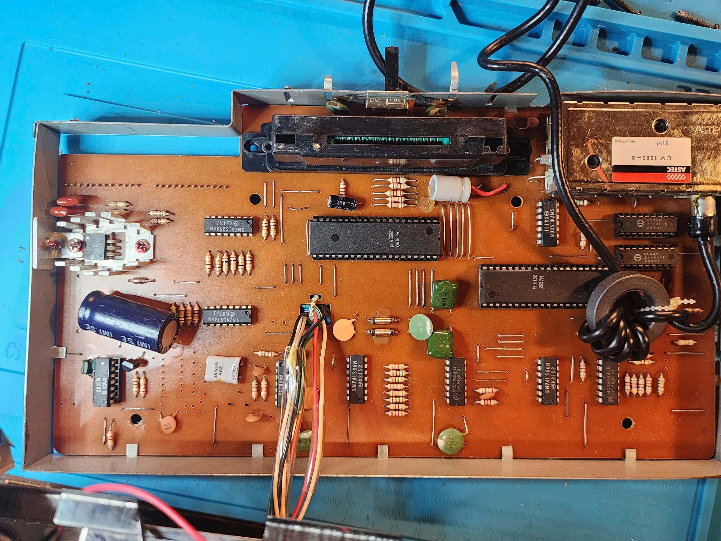
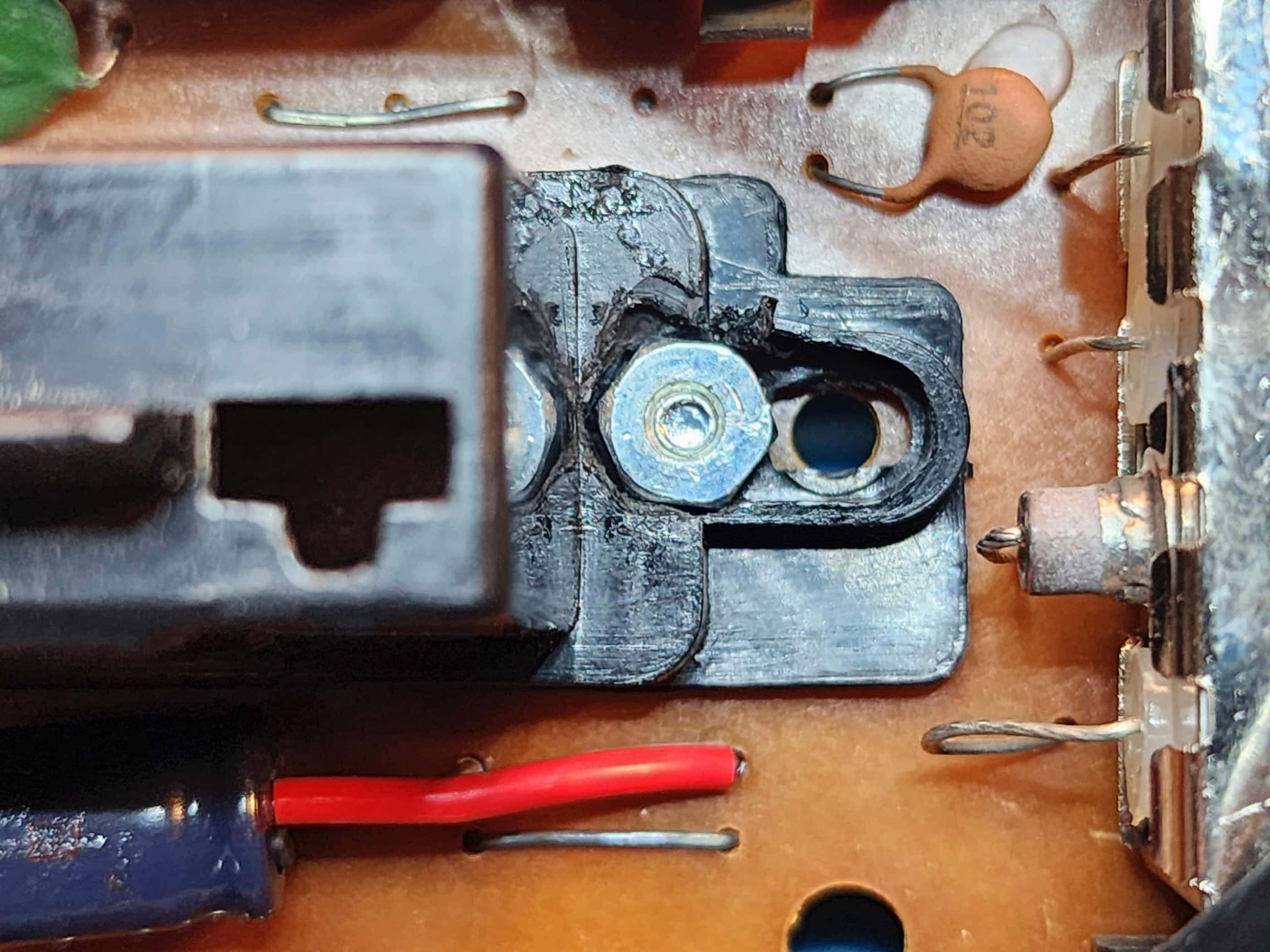
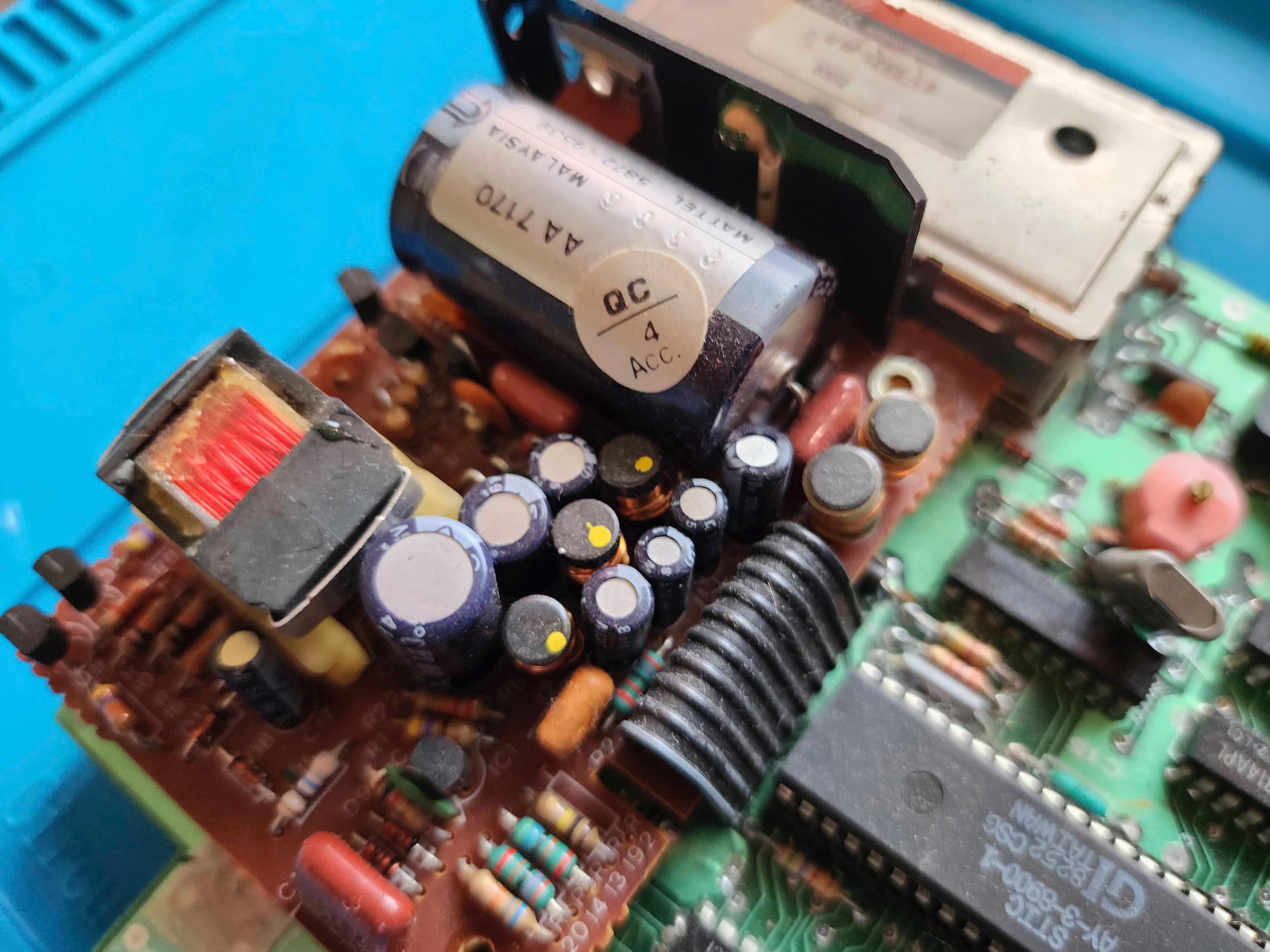
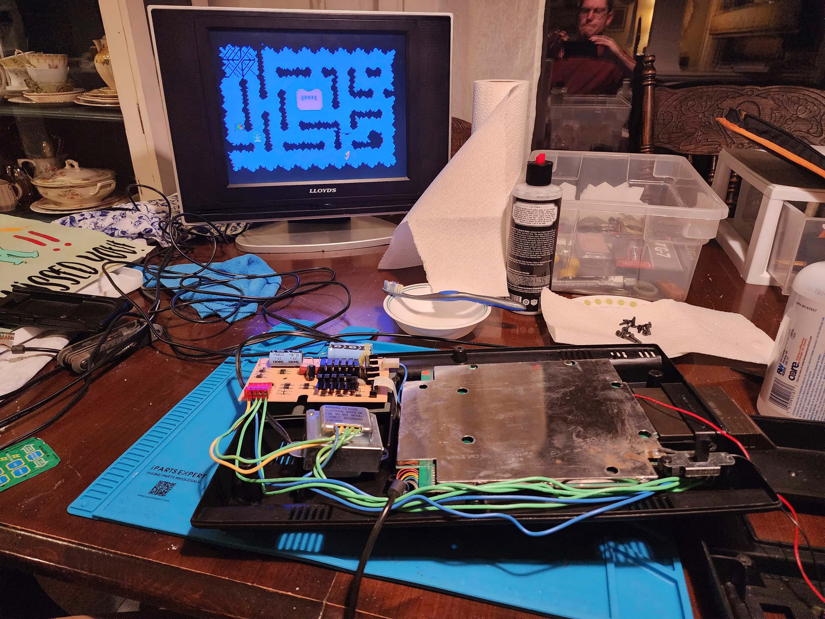
After finally getting the system open, I removed the felt-like liner that covered the area around the cartridge slot, and took note that there were three electrolytic capacitors along with a well-secured 7805 5V regulator. I then started in on replacing the RF cable, which took way longer than I thought it would, as it had been soldered onto the Astec RF modulator with a huge weld. Once removed, I replaced it with a spare cable, though I did not solder it. I then tested the system and it fired up nicely. I tried a few games and took note that the left controller had function problems, notably that trying to move anything down was unresponsive.
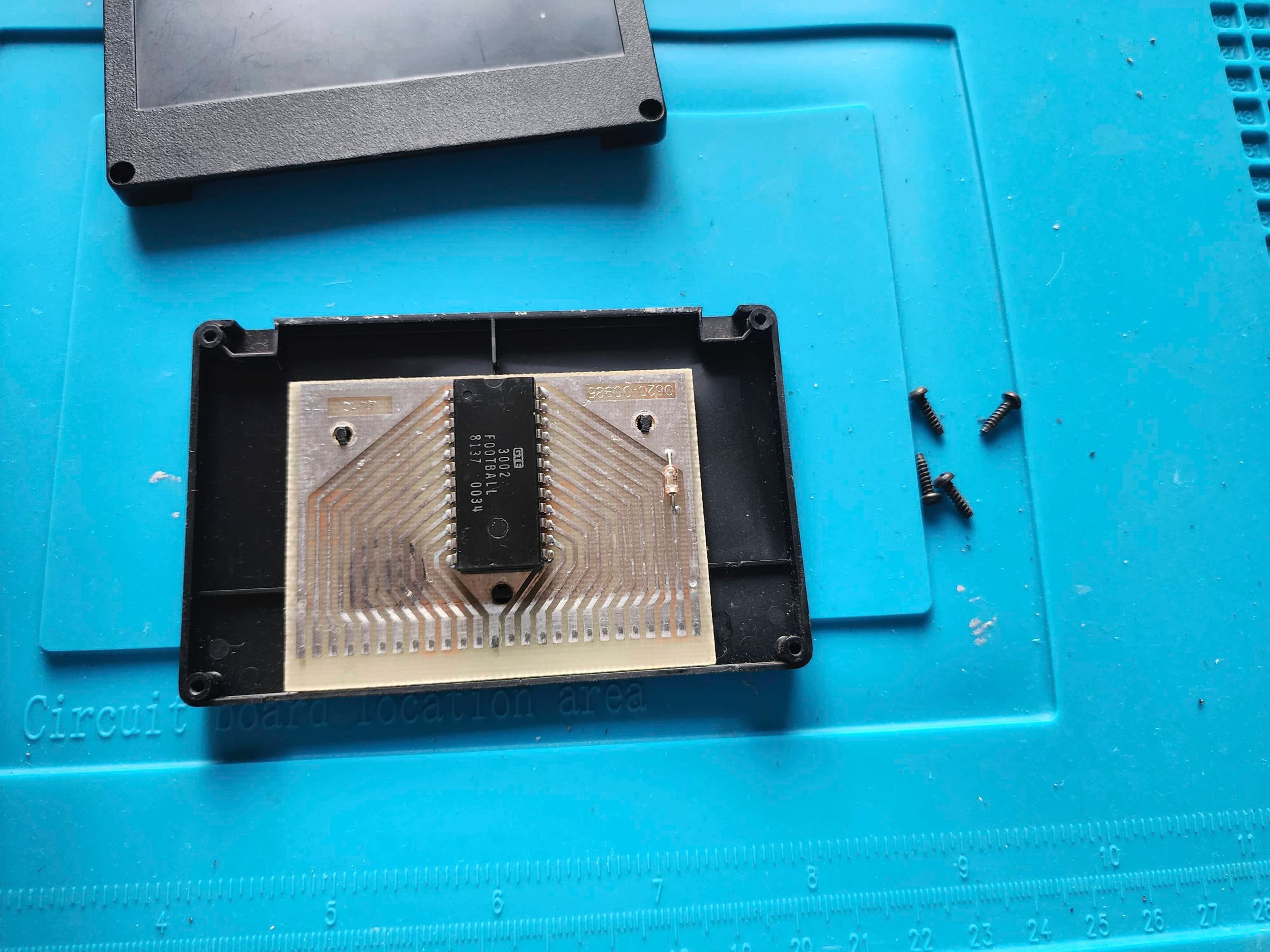
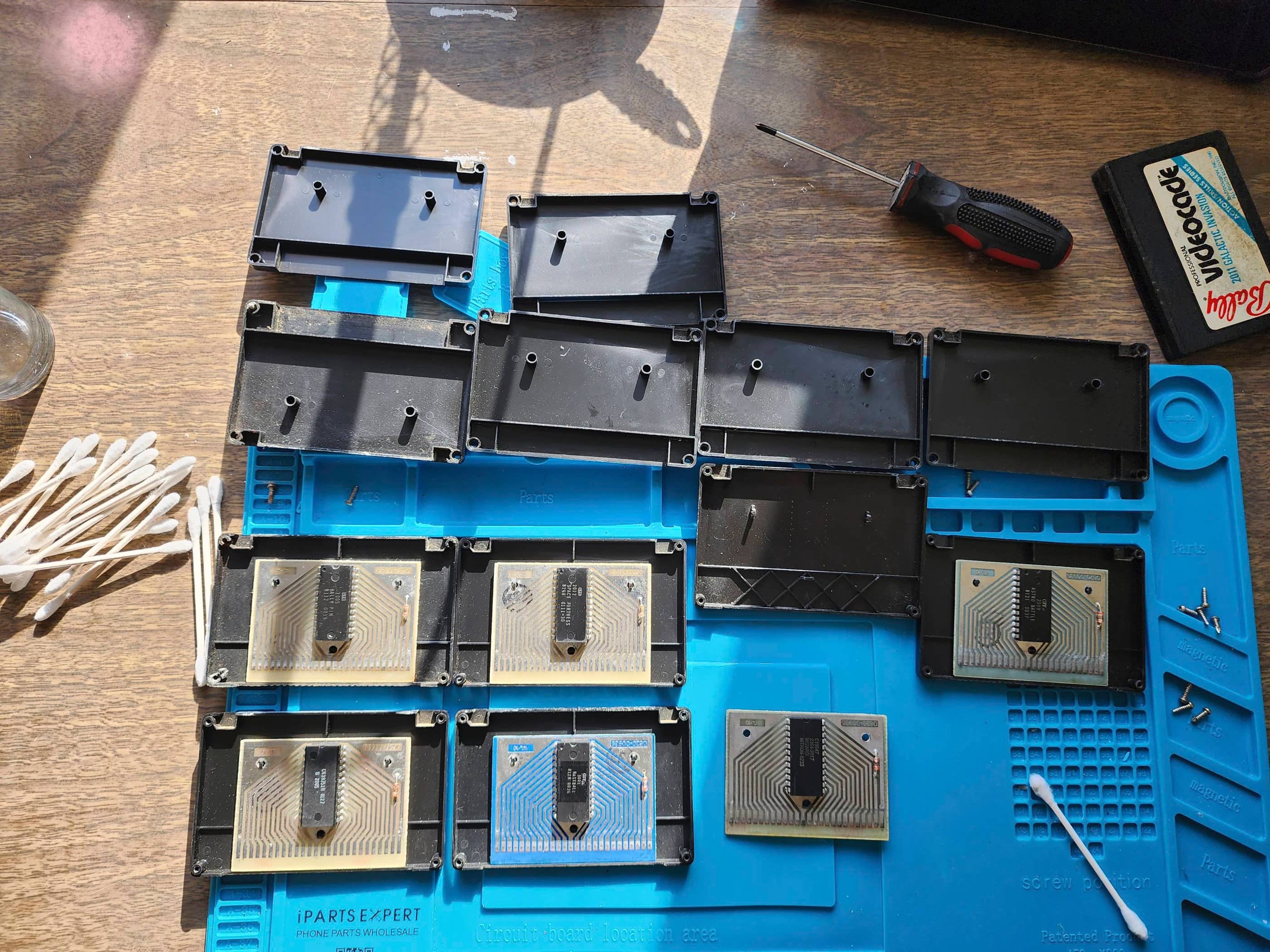
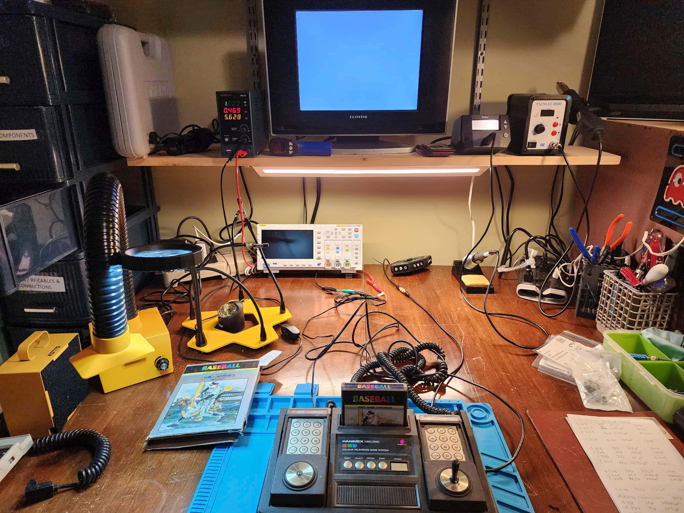
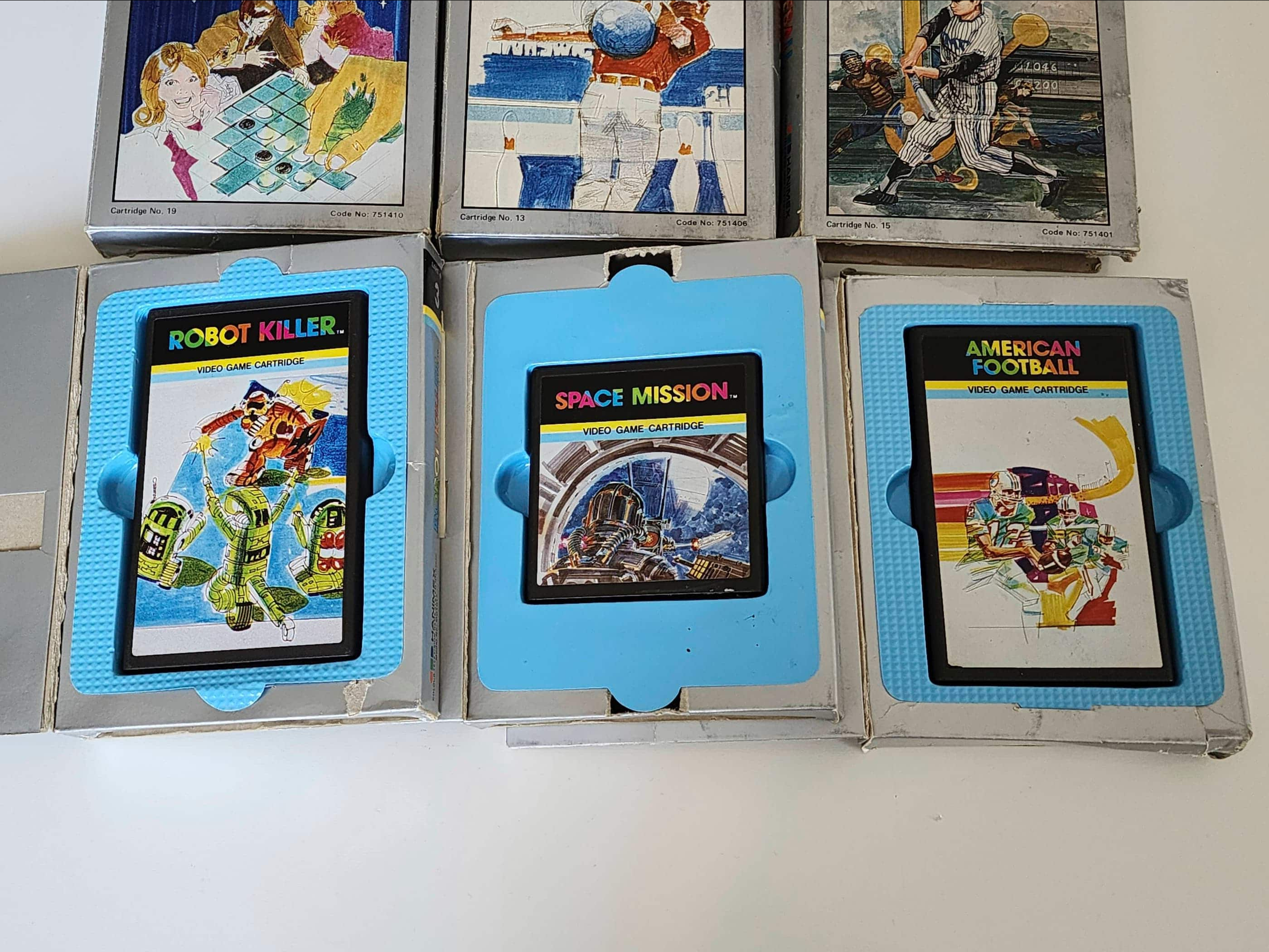
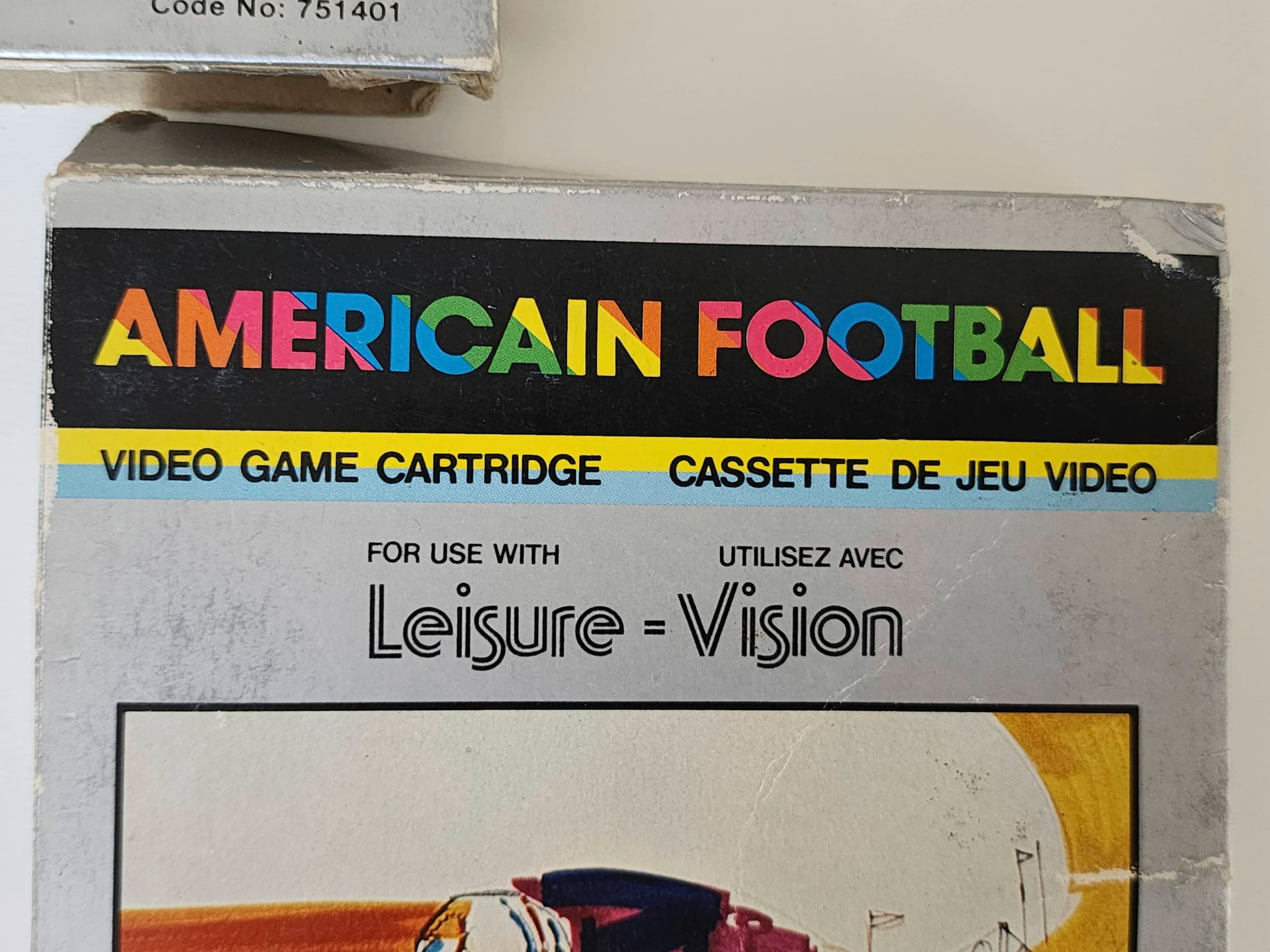
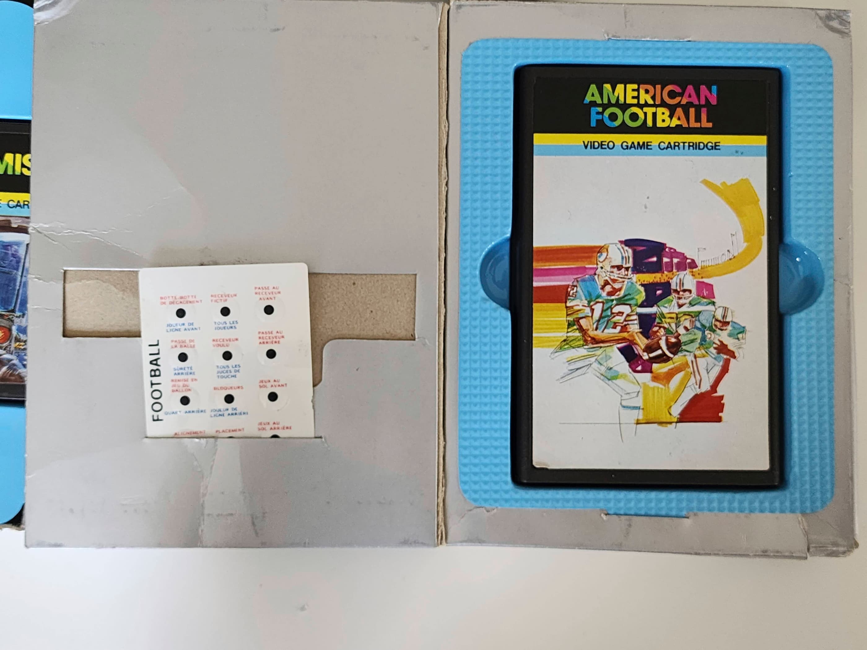
Since the unit was a bit of a pain to open, I figured I’d replace the 7805 5V regulator and the three capacitors so that I wouldn’t have to in the future. Once this was done, I tested the system and ran a few more cartridges through it. That’s when I discovered two of my six cartridges did not work – football or more specifically, ‘Americain Football’ 😂 (note the spelling mistake from the cover) and Baseball. Oh well, the others worked so that’s good.
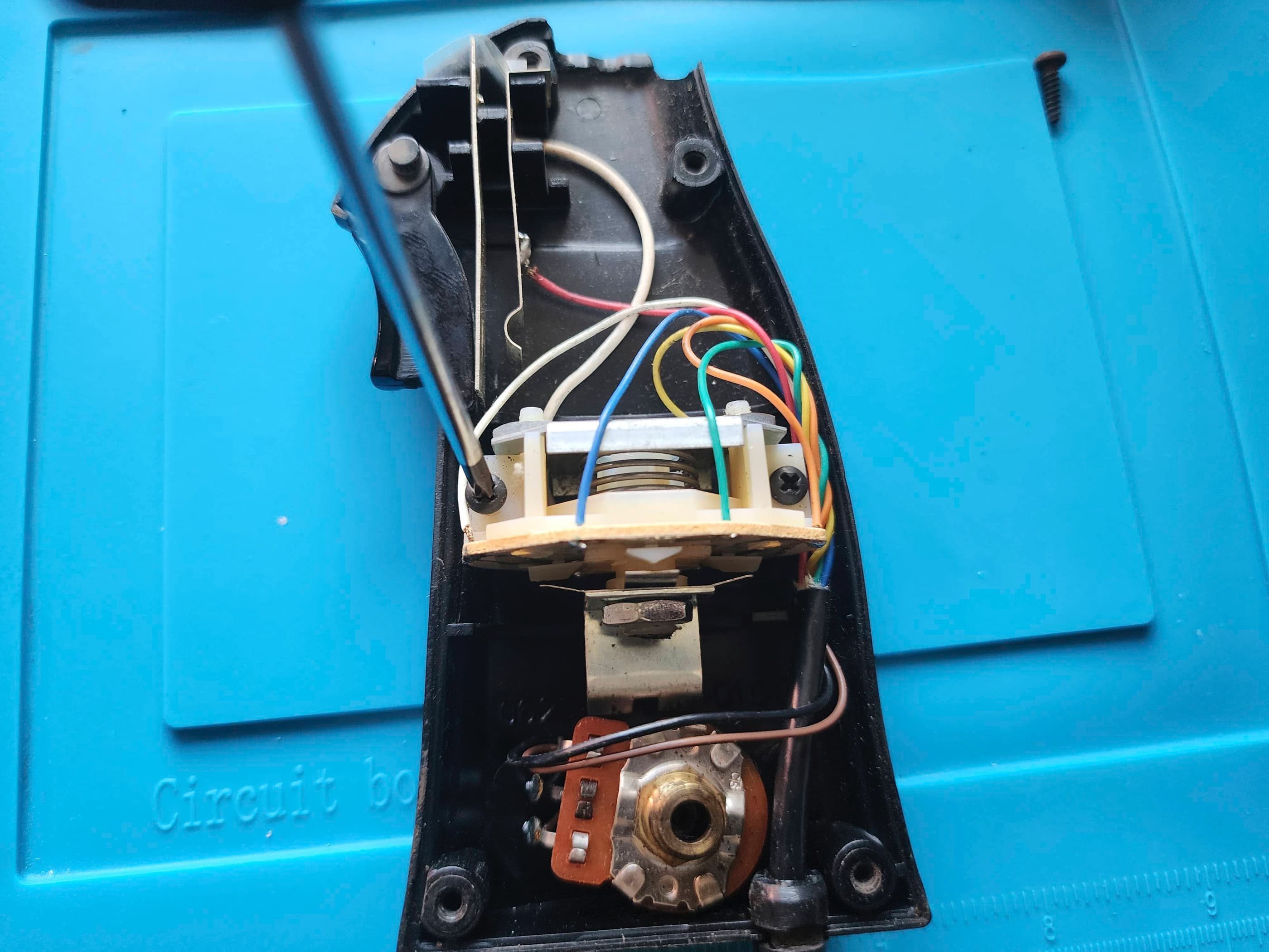
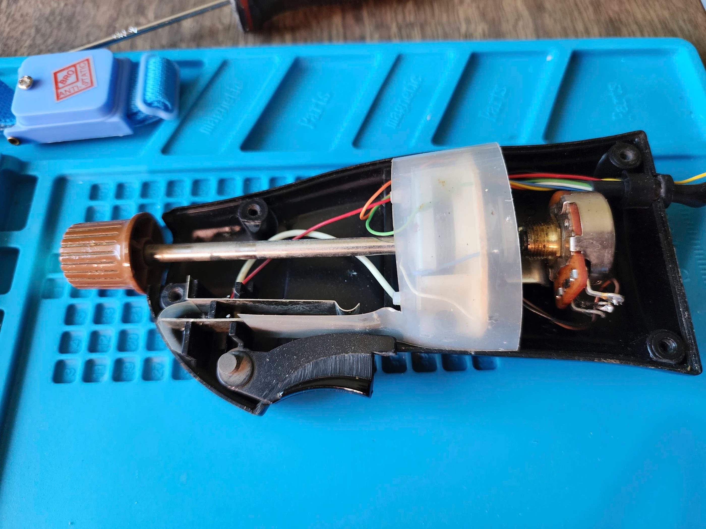
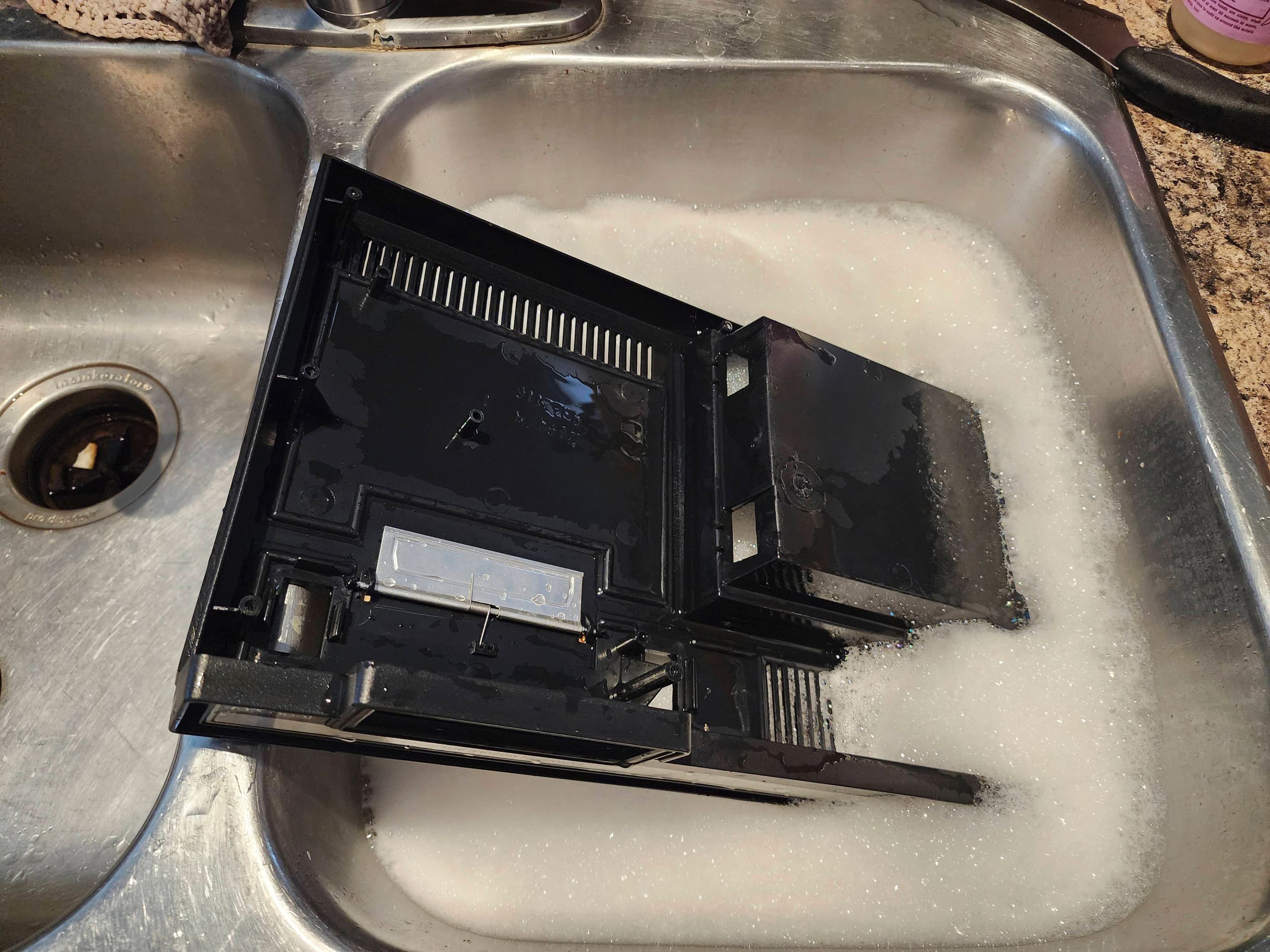
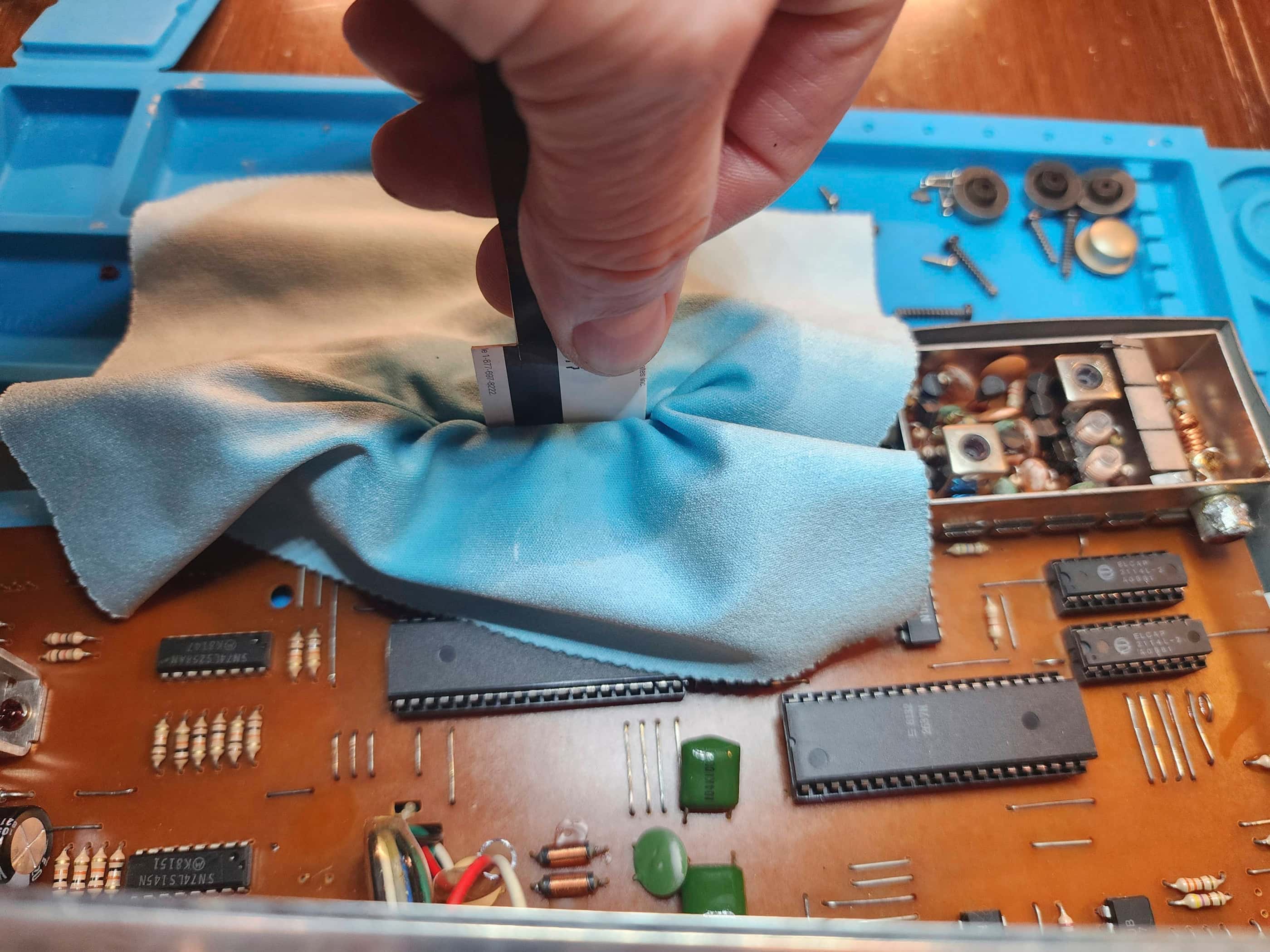
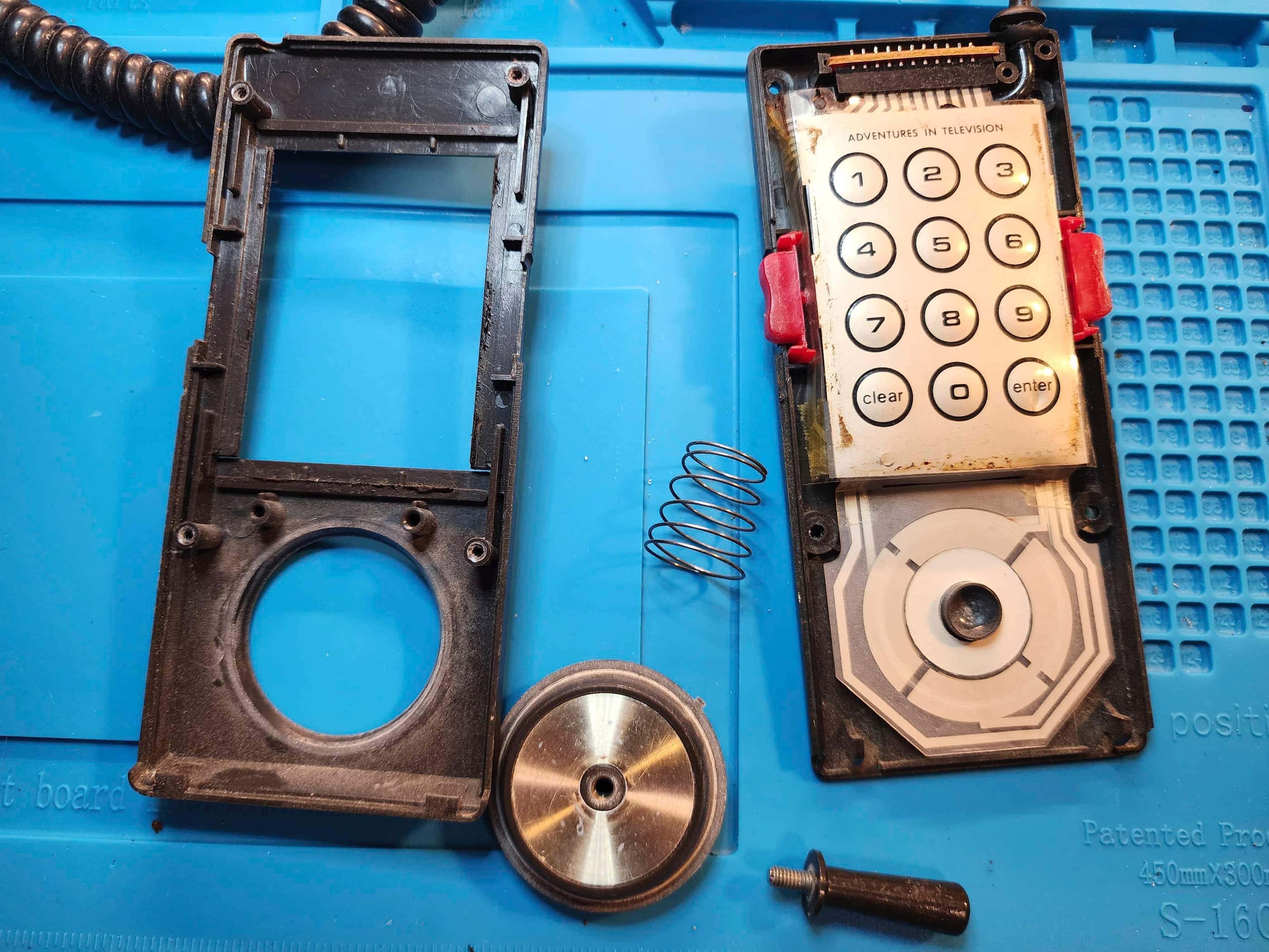
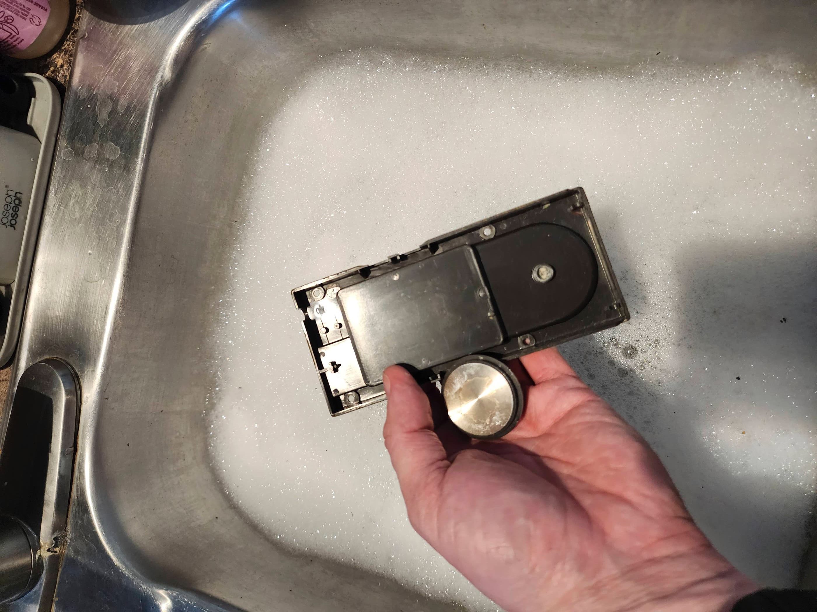
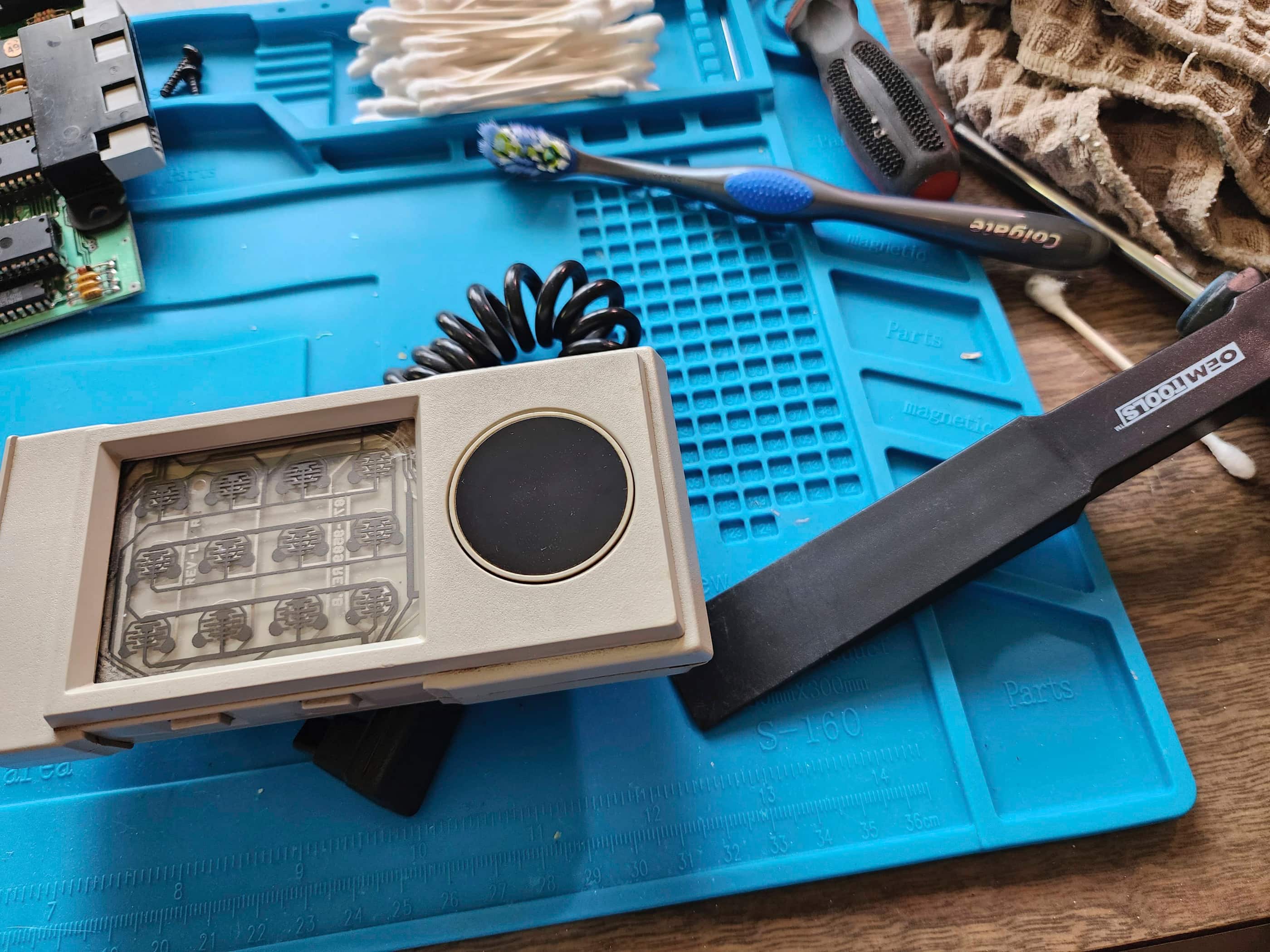
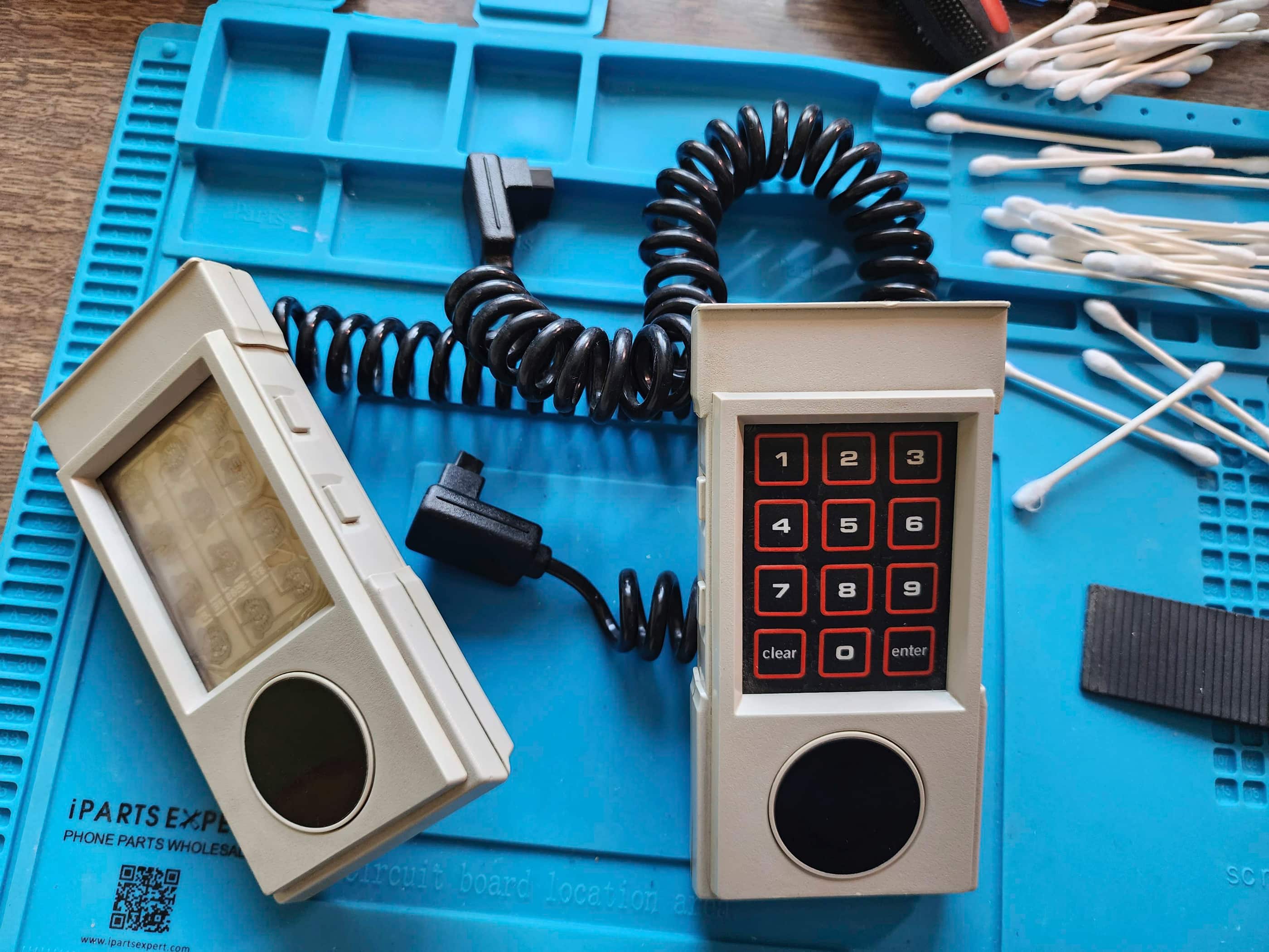
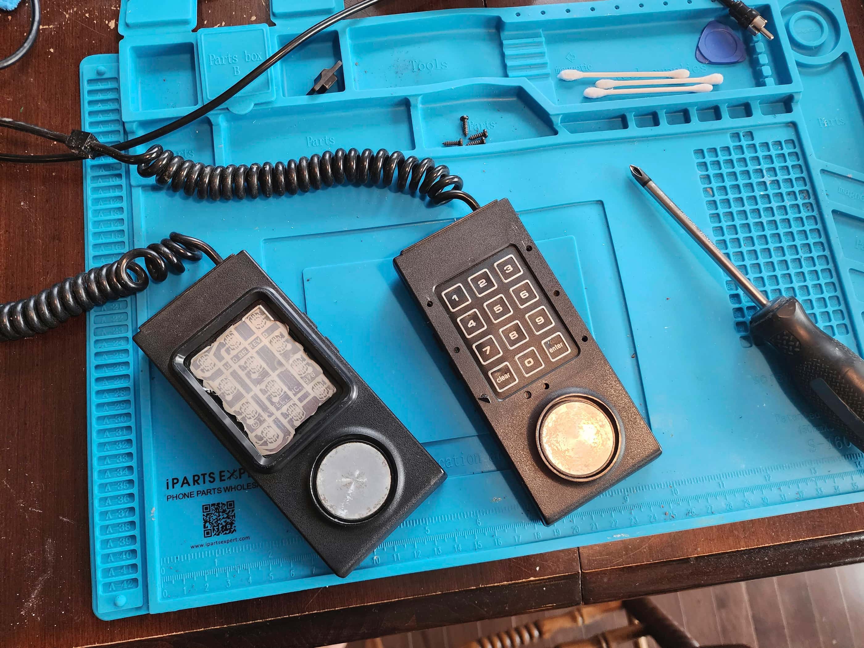
I then gave the console and controller casings a good wash and shine, and set about reassembling the console. When the system was pretty much back together, I focussed in on the controllers which are pretty much direct copies of the Intellivision ones. Thankfully, they copied the original Intellivision controller cases and not the Intellivision II controller cases, as those are the absolute worst to open.
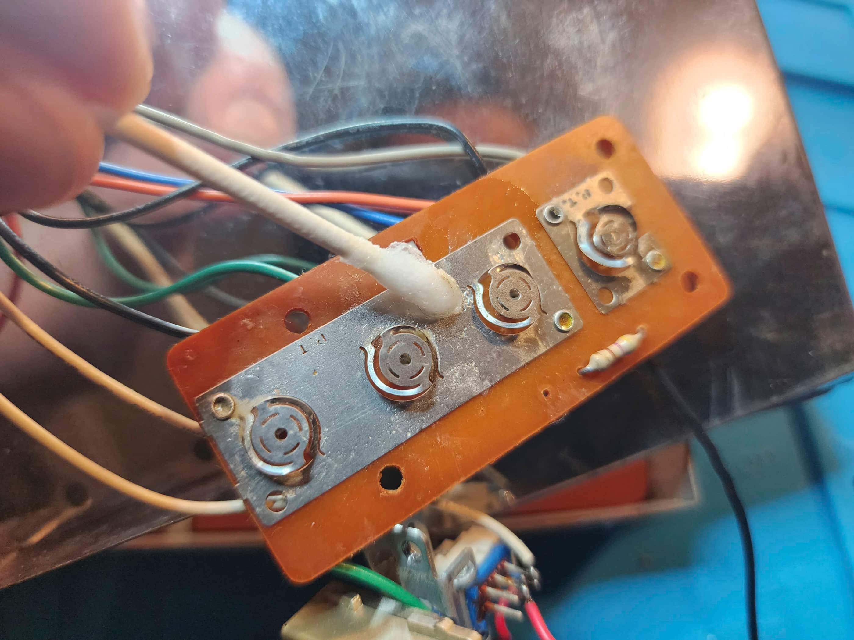
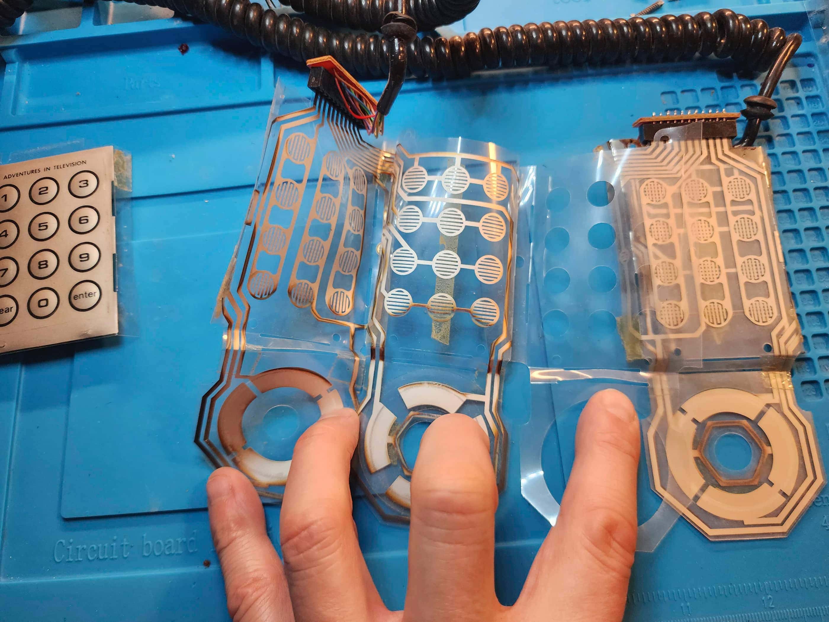
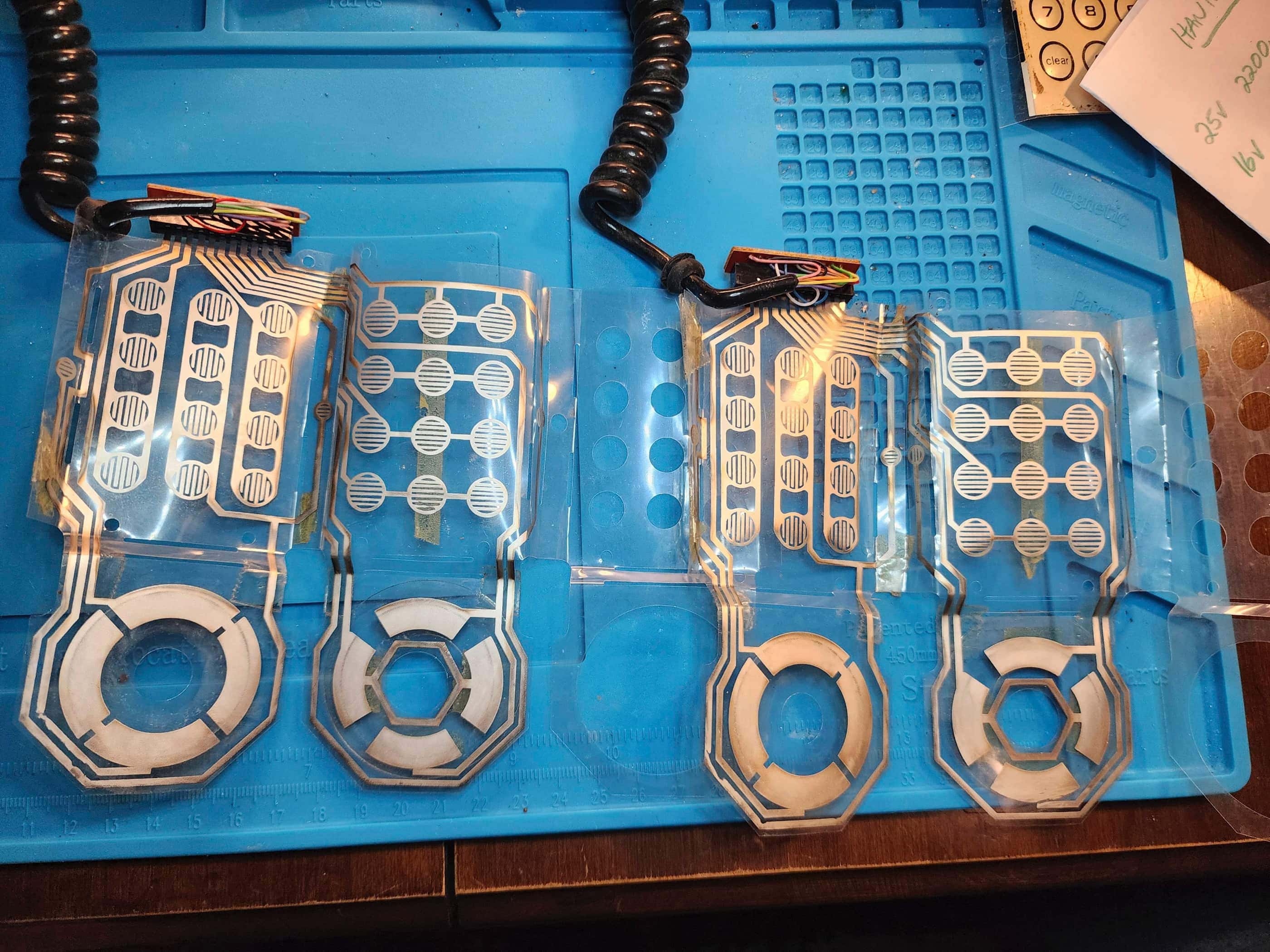
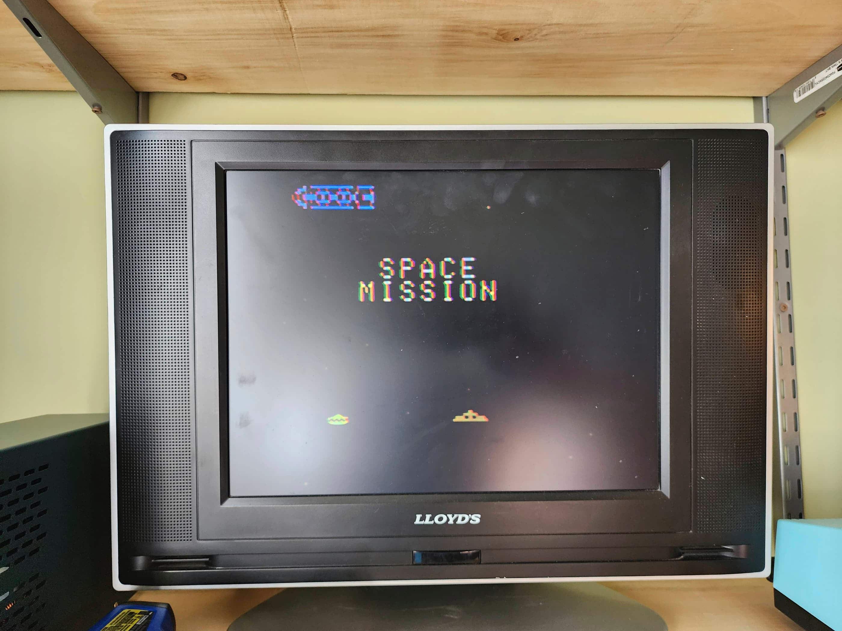
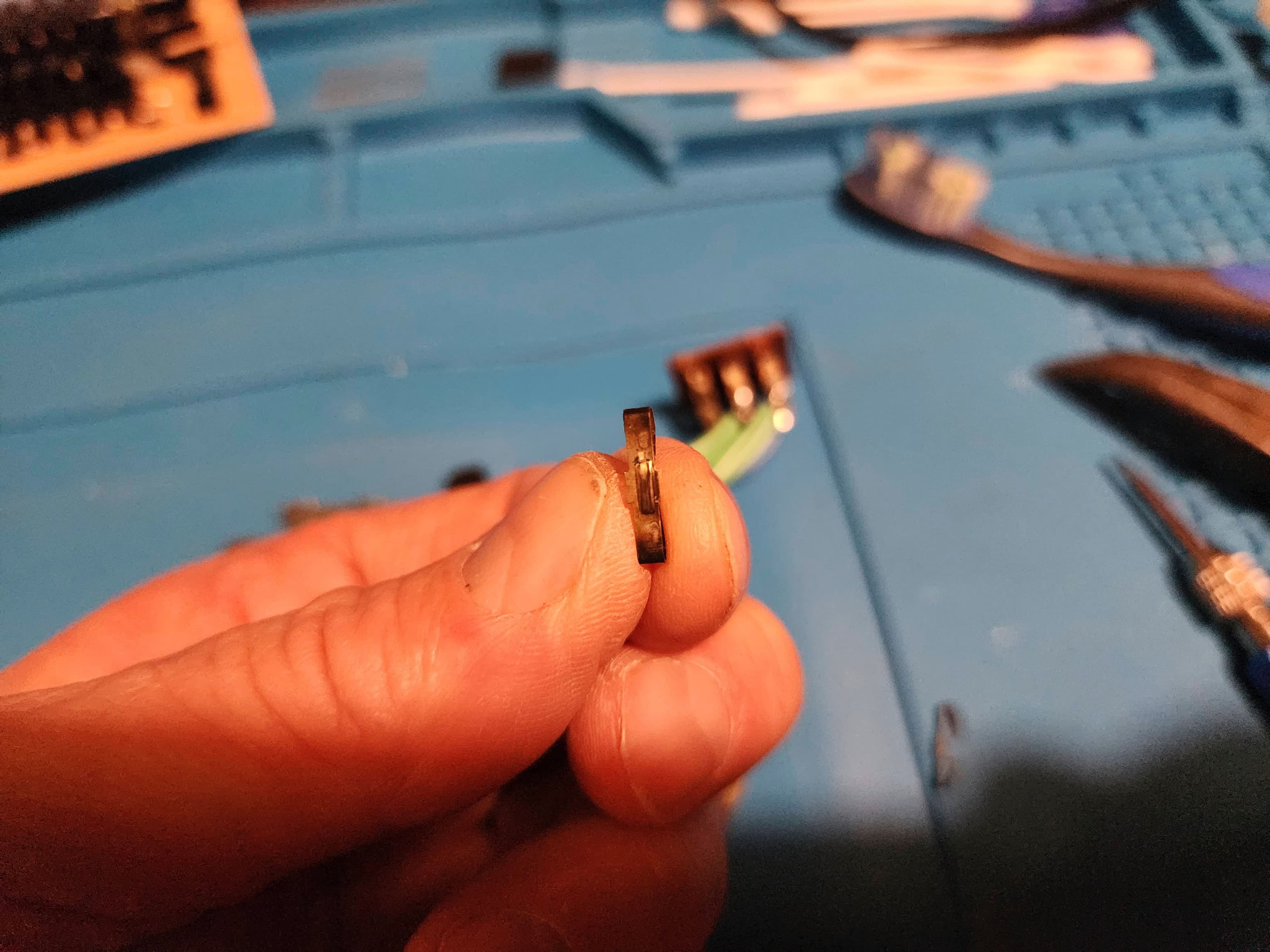
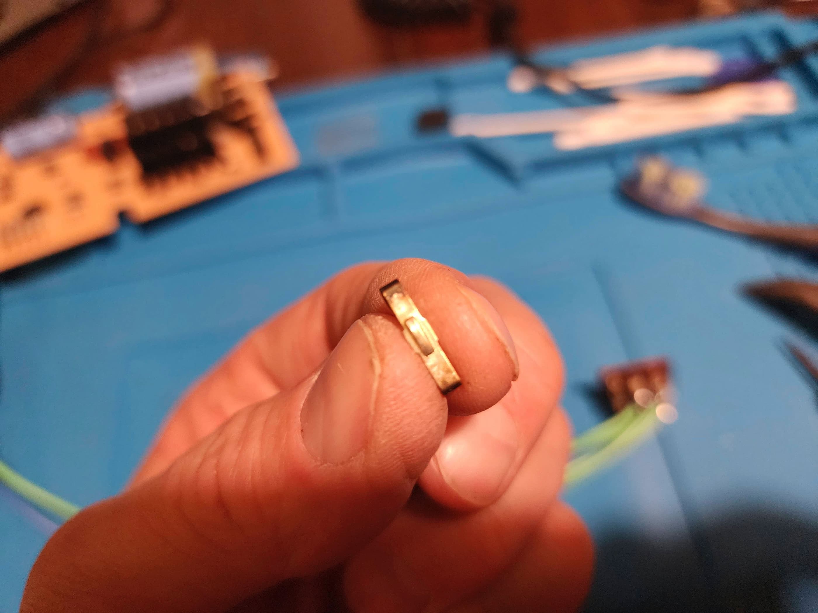
Like the console, the controllers were quite dirty and at some point, someone had spilled a drink that had seeped onto the flex circuit of the left controller. This added extra time to cleaning the contacts with IPA. This is when I noted the reasons why the left controller would not move anything down and why the left fire button did not work: broken traces on the flex circuit. Not have a silver flex painting pen on hand, I improvised a solution using an old Atari 5200 controller flex circuit. Cutting some tiny pieces from the exposed 5200 circuits, I then carefully taped these as bridges to the gaps on the HMG’s controllers. A continuity test indicated that the solution worked, but it still needed to be tested. I plugged in Robot Killer (a Robotron clone) and sure enough, I could move my character around without issue. Though not entirely perfect, the left fire button worked while the right one was flawless.
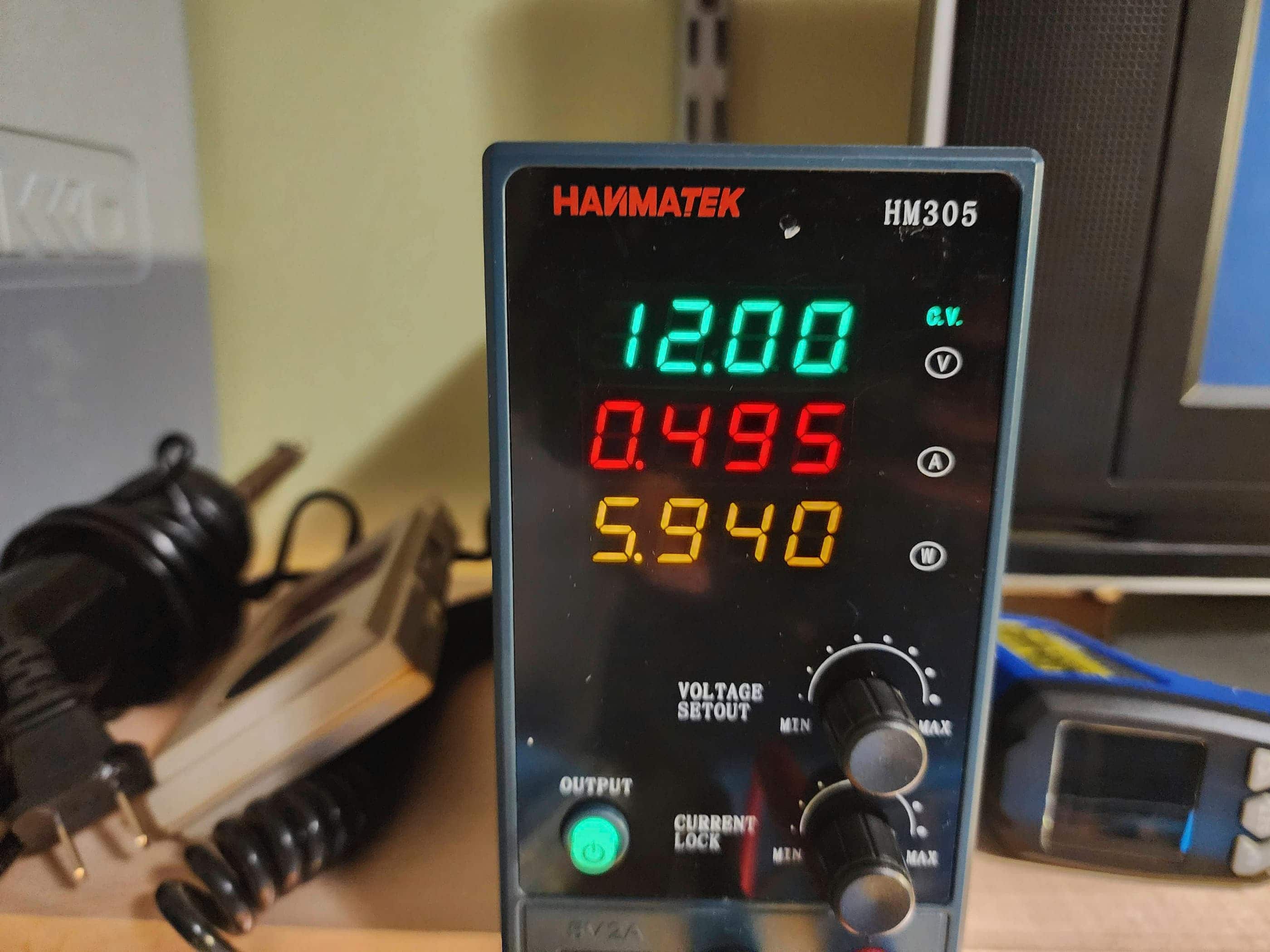
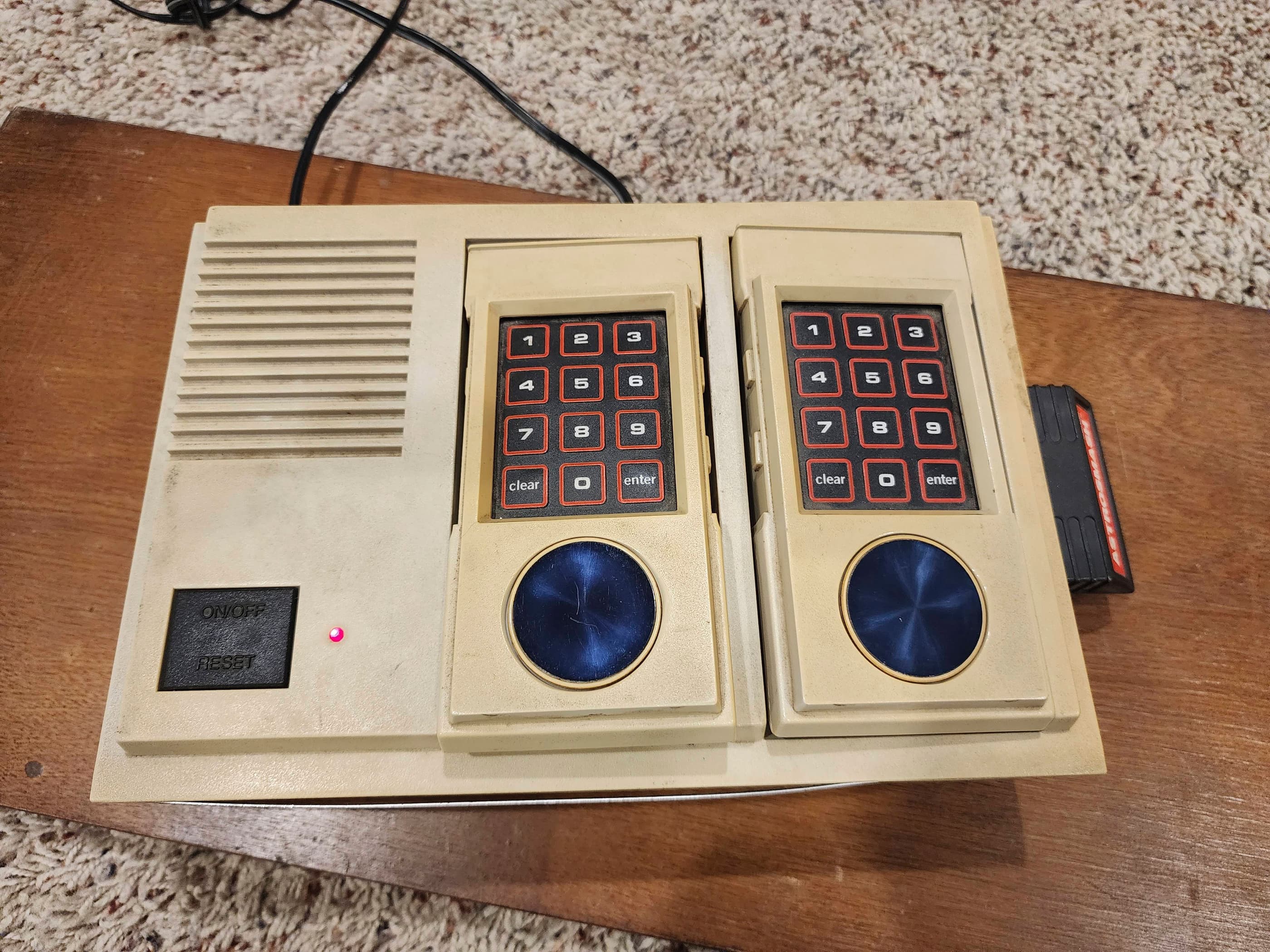
I then reassembled the controllers and the remaining part of the console. Another quick test showed that everything was working as it should. One thing I noted while testing the console, was that depending on the game, my bench power supply showed up to 495 mA being used. Though the back of the console says it needs a 12V 500 mA, I decided to up the amperage of the 12V power supply that I paired with it.
I now have a relatively rare, fully working Hanimex HMG 2650. 😁
Parts & Products Used: 99% isopropyl alcohol; Chemical Guys Natural Shine; thermal paste; 7805 +5v regulator (1); electrolytic capacitors (radial) – 16v 10μF (1); 16v 220μF (1); 25v 2200μF (1); thermal paste; 12v 750mA replacement power adapter
Intellivision (#1)
Years (1979 – 1984)
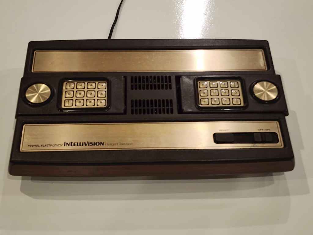
Interesting fact: Mattel pioneered the first handheld electronic game in 1977 and by the late 70s, did not want to be left out of the booming video game market. (source) So, Mattel developed the “Intelligent Television” or Intellivision Master Component to rival the Atari VCS; test releasing it in the fall of 1979 and then fully releasing it in 1980. (source)
Condition When Acquired: Fully Functional
Current Condition: Fully Functional


Project Details: I love it when I get a console that has been so well taken care of! This Intellivision came bundled with Intellivision #2 from the original owner. Even the game boxes were in pristine condition and included the instructions and keypad overlays. The only thing that I’ve had to do with this console, is take it and the controllers apart and clean them. I debated trying to remove and glue down the metal labels on the top of the console, but removing them – even after heating – is tricky and can still crease or dent them. As the peeling wasn’t too bad (yet), I decided to leave it until I can get a parts unit that I can swap it with. However, a few months later, I found Intellivison #4 for a shockingly good price and my problem was solved: I simply swapped the two top covers. This woodgrain throwback to the late 70s / early 80s now looks and functions perfectly. 😁
Parts & Products Used: 99% isopropyl alcohol; Chemical Guys Natural Shine;
Intellivision (#2)
Years (1979 – 1984)
Interesting fact: Intellivsion introduced a number of firsts for video games: 1) it had the first 16-bit microprocessor; 2) it was the first system to have downloadable games through PlayCable; 3) its controllers were the first to have a 16 direction d-pad; 4) it was the first to have a music synthesizer; and 5) it was the first system to have a built-in complete character font. (source)
Condition When Acquired: Partially Functional – controller issues
Current Condition: Fully Functional

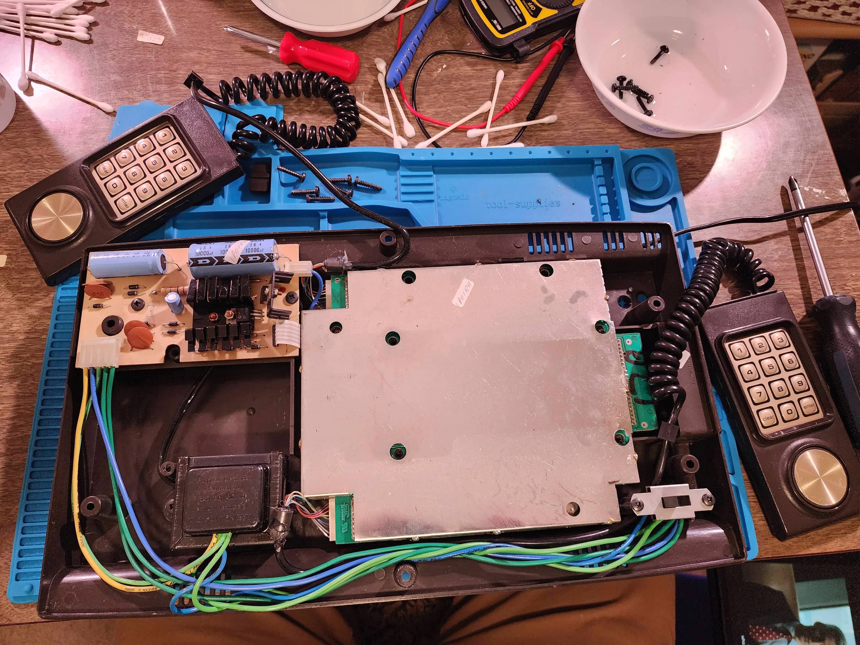


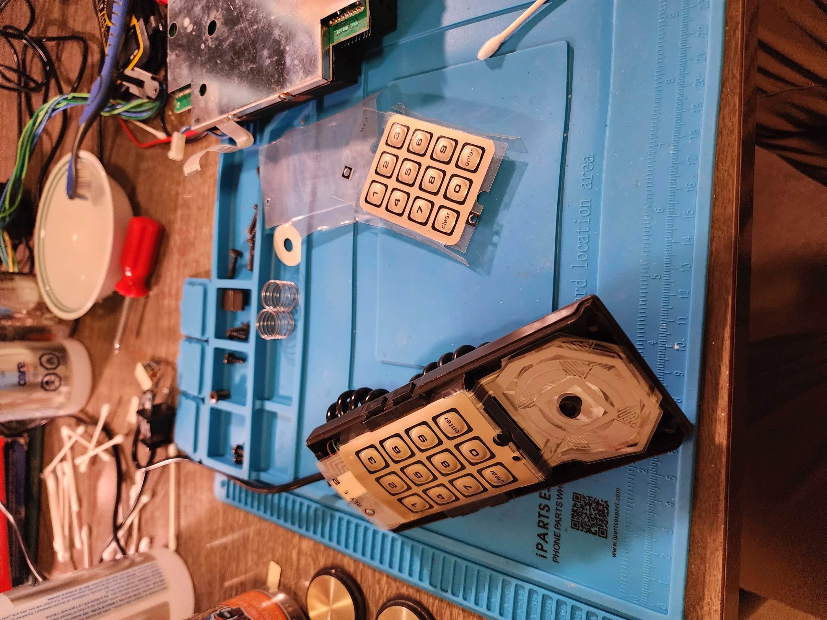
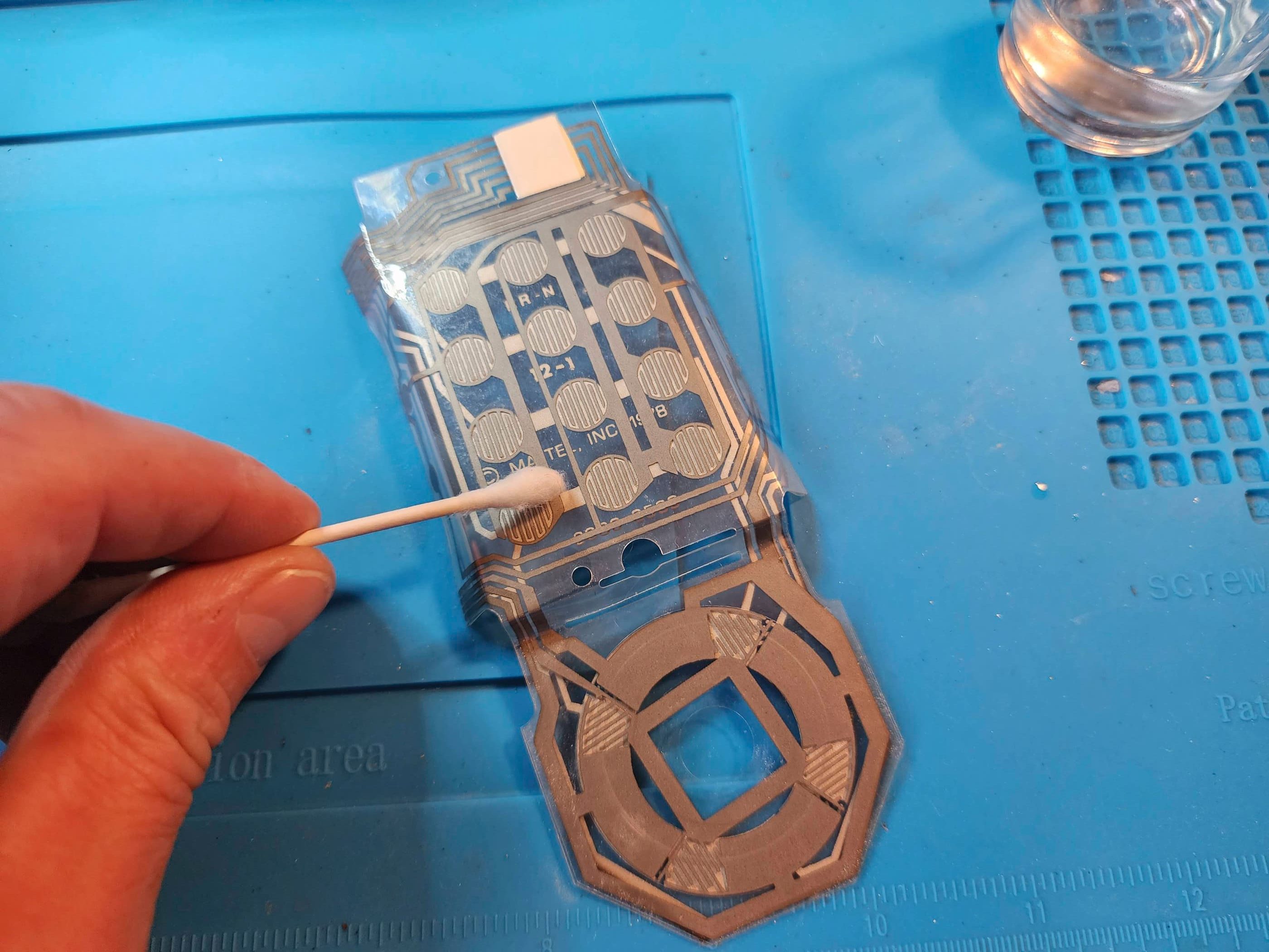
Project Details: I acquired this with Intellivision #1, but this unit had definite issues with its controllers. The left controller directional pad did not work and only the bottom fire button on the right side worked. The right controller directional pad only worked when pressed to the right, and just like Zoolander, it couldn’t turn left. 😂 However, all the fire buttons worked. I then pulled the unit apart as well as each controller. For the right controller, I cleaned the flex circuit contacts with IPA but this didn’t fix the issue. I did the same for the left controller and the responsiveness of the directional pad increased marginally but not enough for gameplay. I also couldn’t fix the fire buttons. I did however, give the machine a cleaning and polishing. Like Intellivision #1, I held off on trying to glue down the metal strip on the casing. After waiting almost a year, I finally found Intellivision #3 as a parts machine from which I could harvest flex circuits. For the left controller, the new flex circuit fixed all the issues. However, after swapping the flex circuit on the right controller, the same inability to move left persisted, which told me that it was either a cable issue or a board issue – and I was really hoping it was the cable. A quick cable swap from Intellivision #3 solved the problem and the controller was now fully operational. Whew! As the top case was also in better shape on unit #3, I also swapped this. This system is now fully functional. 😁
Parts & Products Used: 99% isopropyl alcohol; Chemical Guys Natural Shine
Intellivision (#3)
Years (1979 – 1984)
Interesting fact: Though Intellivison had superior graphics and sound to the Atari VCS, it could not compete for licensing popular arcade titles. (source) It did however, secure licenses from a number of major sports leagues for its games, such as the NHL, NBA, NFL, and MLB. (source)
Condition When Acquired: Partially Functional – graphics issues
Current Condition: Active Project / Parts System
Project Details: Due to its cosmetic condition, this unit was cheap to buy. That it was supposed to be fully function was a huge bonus because I bought it simply to be a parts unit, in particular, for its controller flex circuits for use in Intellivision #2 (see above). The condition of the mylar keypads on the controllers was also good news as they were in almost mint condition. After popping in an Astro Smash test cartridge, I turned the system on and was met by garbled graphics. A quick reset made the game playable, but the graphics where still glitchy. Since I was using the machine primarily for its controllers, I focused on whether they worked and they did. To test the up/down functionality, I put in Night Stalker and still encountered garbled graphics. However, the controllers functioned as they should and so I harvested the top case, the flex circuits and a cable for use on Intellivision #2. One day I’ll return to fix this machine…
Parts & Products Used: None yet

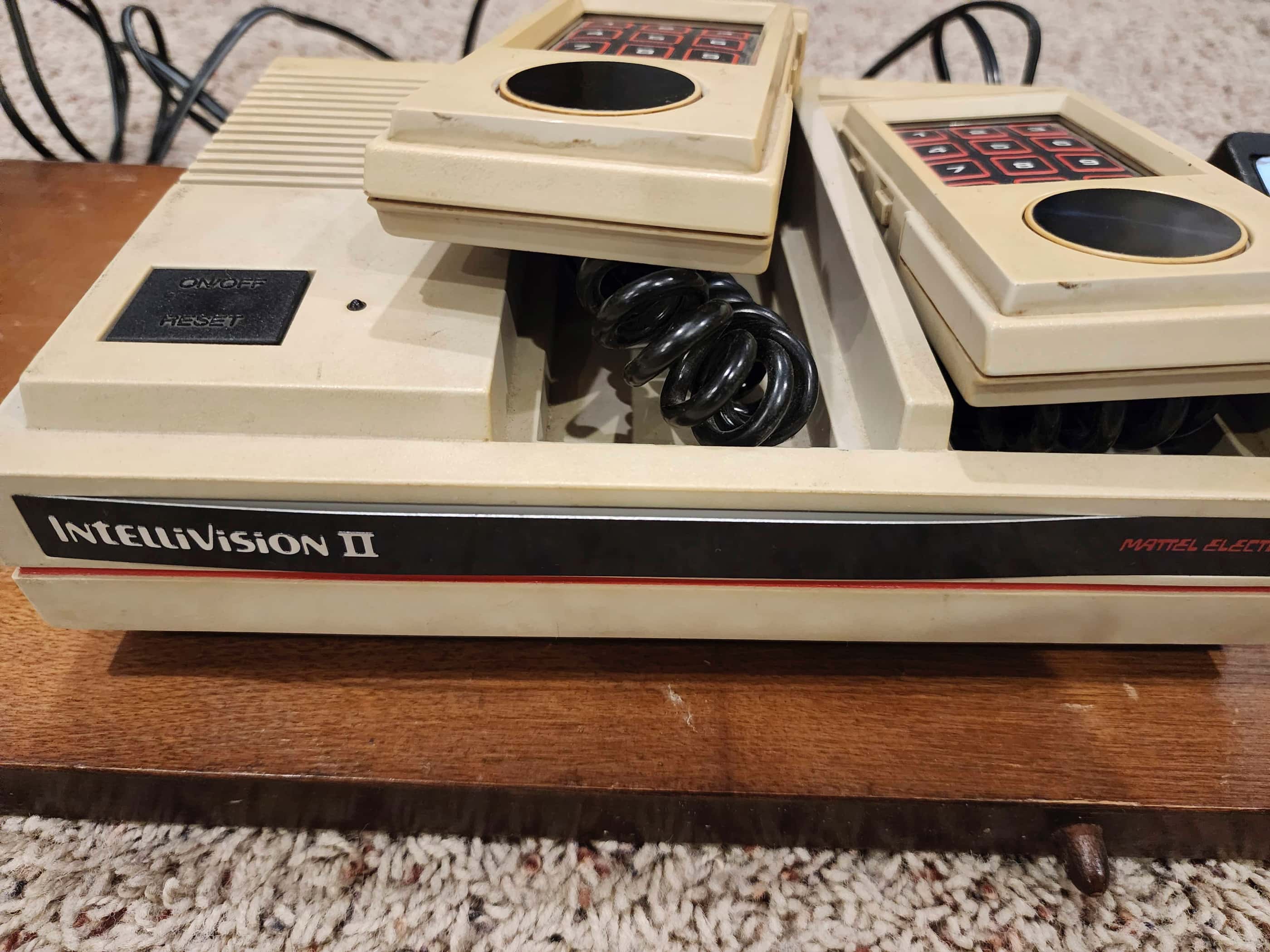
Intellivision II (#1)
Years (1983 – 1984?)
Interesting fact: In 1983, Mattel released slimmed down version of the Intellivision to try and spur on sales while concurrently, reducing the costs of manufacturing. The Intellivision II featured a modern white case, detachable controllers, and a much smaller footprint. Unfortunately, it also included a dumbed-down sound chip and poor quality parts. (source)
Condition When Acquired: Partially Functional – controller issues
Current Condition: Fully Functional


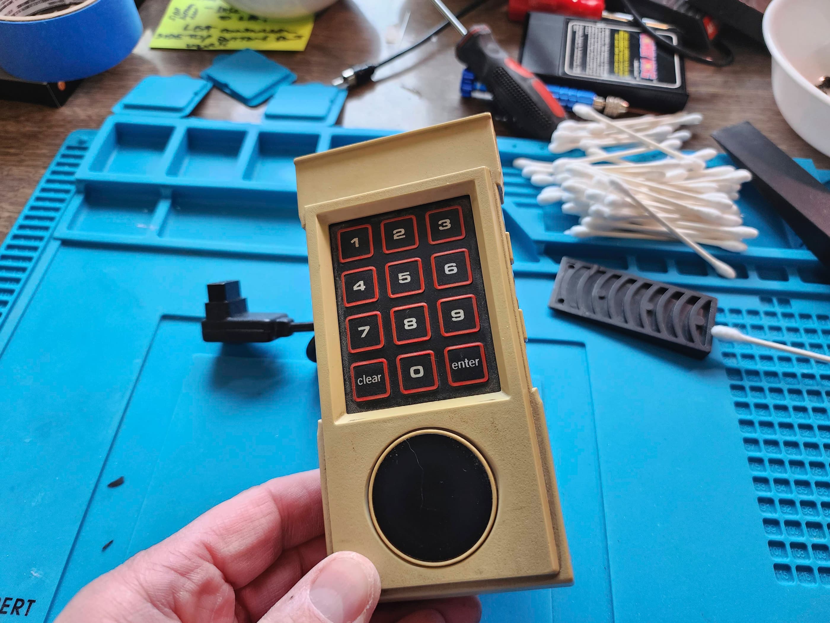
Project Details: I purchased this, along with Inty II #2 and Inty II #3 all within a couple weeks of each other from different sources. My goal was to try and cobble together one complete system from the three. This particular unit was missing the proprietary16.2 VAC power adapter and the keypads on both controllers. What I did like however, was the white plastic case was in excellent condition and showed no signs of yellowing. The unit was untested when I received it and as the other two Inty IIs had not yet arrived, I had no way of knowing if it worked because the power supply is not something I could swap from another system. That is, until I found an article on retrogamestart that said you could use an IBM Lenovo Thinkpad 16v 3.36a power adapter. Hmmm…. I went down to my local thrift store and found the recommended adapter for less than $10. I brought it home, plugged it into the system, popped in a Night Stalker cartridge, and turned it on. It worked! The game came on without issue and surprisingly, both controllers more or less worked.
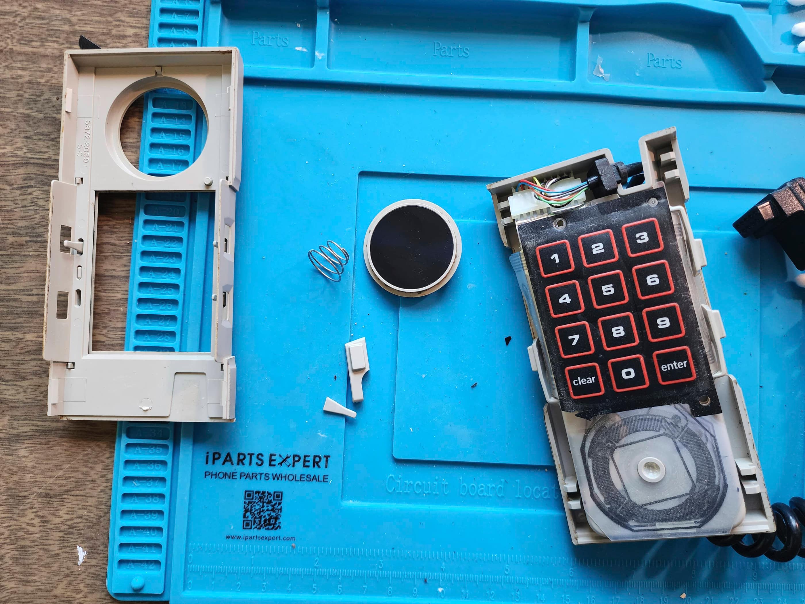
I then got to work taking the system apart and cleaning it. I have to say, the Inty II controllers are the worst controllers to work on because they are so cheaply made. There aren’t any screws holding the casing together like the original Intellivision controllers and the Inty II buttons are simply plastic appendages attached by a thin arm to the back half of the casing. Pulling these things apart it is a risky endeavour because there are double plastic hooks on each corner of the back casing that hold the front and back pieces of the case together. They easily break and if they do, then the controller won’t go back together snugly. Nevertheless, I got both controllers apart without damage, cleaned the flex circuits with IPA (they were dirty!), and then carefully reassembled the controller. The controllers now worked great but I still needed to replace the keypads. I then disassembled the controllers and left them that way until the other Inty II’s arrived.
When Inty II #2 arrived, one controller was missing the number pad and the other had crack in it, so I couldn’t use these. When Inty II #3 arrived, it looked worse for wear, but the keypads were in mint condition even though the controller casings were yellowed and damaged. I then disassembled the controllers from all three systems and laid them out for further testing and inspection. Amazingly, the flex circuits from Inty II #3 worked perfectly, so I just ported these over to the undamaged controller cases from Inty II #1. As the directional discs from Inty #2 were in mint condition, I swapped these in as well. I now had two controllers made from three systems that looked and functioned like they were new. I also included the working proprietary power adapter from Inty II #3. Thus, Inty II #1 is now a complete system that looks and functions fantastically. 😁
Parts & Products Used: 99% isopropyl alcohol; Chemical Guys Natural Shine; replacement controller flex circuits and mylar keypads from INTY II (#3); replacement controller directional discs from INTY II (#2);

Intellivision II (#2)
Years (1983 – 1984?)
Interesting fact: Mattel tried to get around the emergence of third-party developers by secretly including an internal ROM program in the Intellivision II that would not play games made by companies such as Coleco. (source)
Condition When Acquired: Partially Functional – graphics and controller issues
Current Condition: Fully Functional


Project Details: This one arrived shortly after Inty II #1 and came as a ‘working but with issues’ tag. After testing the proprietary power adapter and confirming it was good, I fired up the system with Astro Smash as the test cartridge. The game worked with the proper sounds but the graphics were glitchy. Both controllers were missing the mylar keypads and neither worked properly; yet the directional discs were in amazing shape. I opened the unit and got to work inspecting an cleaning the board. A thorough application of IPA to the cartridge slot fixed the graphics glitching. I disassembled the controllers and determined that only one had an undamaged case. I then put everything aside until INTY II #3 arrived. Once it arrived and I had rebuilt INTY II #1, I took the working flex circuit and cracked keypad from INTY II #1 and paired it with the good casing that came with this unit. I parked the other working flex circuit in its own container until I can one day find a new controller case and keypad(s). For now, this is a fully functioning system with one controller.
Parts & Products Used: 99% isopropyl alcohol; Chemical Guys Natural Shine; replacement controller flex circuit from INTY II (#1);
Intellivision II (#3)
Years (1983 – 1984?)
Interesting fact: With the Intellivision II, Mattel also got rid of the internal power supply of the original Intellivision, replacing it with an external power adapter. However, the 16.2 VAC was non-standard and posed the risk of making the console inoperable if lost. (source)
Condition When Acquired: Partially Functional – controller issues
Current Condition: Active Project / Parts System


Project Details: I bought this solely as a parts unit because the mylar keypads on the controllers were in amazing shape, something that’s really hard to find. However, outside of the keypads and flex circuits, the controllers were trashed and the plastic casing was significantly yellowed. The seller sold the unit for quite cheap and had no idea if it would work. On arrival, I tested the power adapter and confirmed it was good. I then checked to see if system would power up after I inserted a cartridge. Not expecting anything to happen, I was shocked when it fired up Night Stalker without any issues. Cool! After harvesting the mylar keypads and flex circuits to use on Inty #1, I parked this unit on my shelf to one day add new controllers and either a new case or try a UV-H2O2 whitening treatment. I also paired the IBM Lenovo 16v 3.36a power adapter (model:AA20530) that I first tried with Inty II #1 to work as the unit’s power supply because I took the proprietary supply that came with it to also use in Inty II #1. As none of my remaining controller cases are good, nor do I have any number pads, this system is still sitting in my project box. I did swap its power jack with my Atari 5200 2 port, so I’ll have to replace this at some point, but it works good enough for now.
Parts & Products Used: 99% isopropyl alcohol; Chemical Guys Natural Shine; IBM Lenovo 16v 3.36a power adapter (model:AA20530)

INTV System III (#1)
Years (1985 – 1990)
Interesting fact: After the video game crash in 1983, Mattel lost hundreds of millions of dollars and had to liquidate Intellivision. (source) The rights were sold in 1984 to Terrance Valeski, a former VP of Mattel who formed a new company called INTV Corp. After selling through the remaining supplies of Intellivision II, INTV then re-packaged and re-released the original Intellivision as the INTV System III. (source; source)
Condition When Acquired: Partially Functional – controller issues
Current Condition: Fully Functional


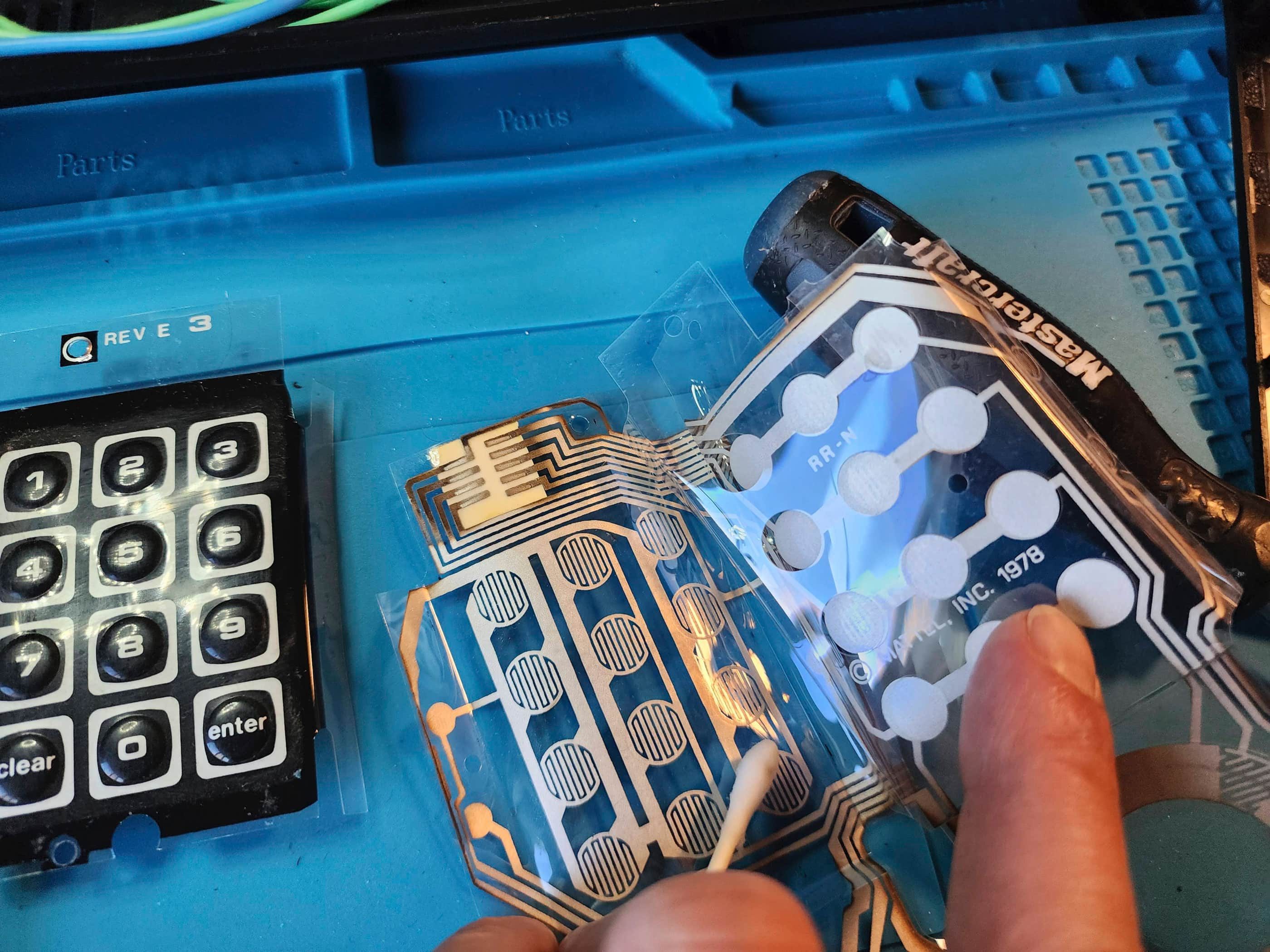
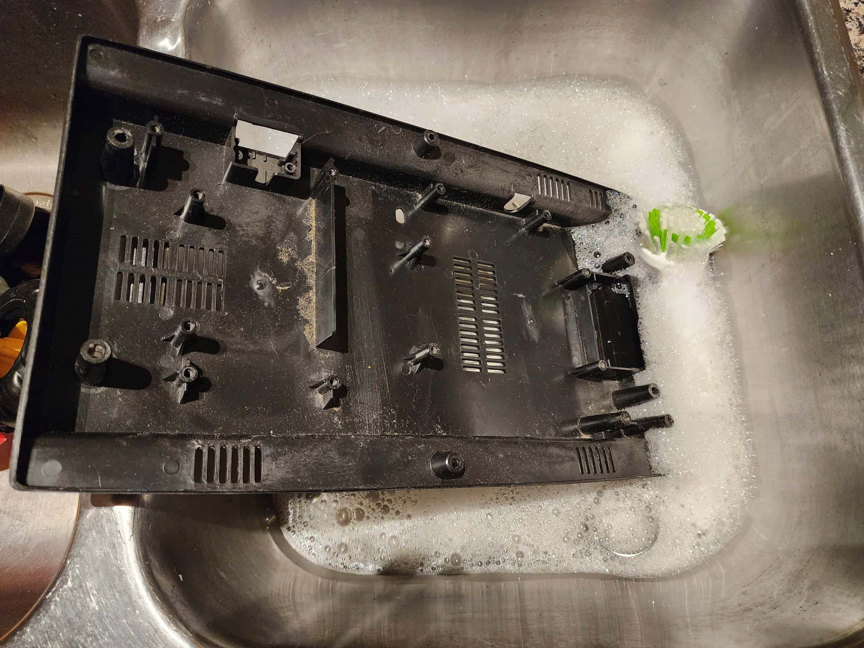

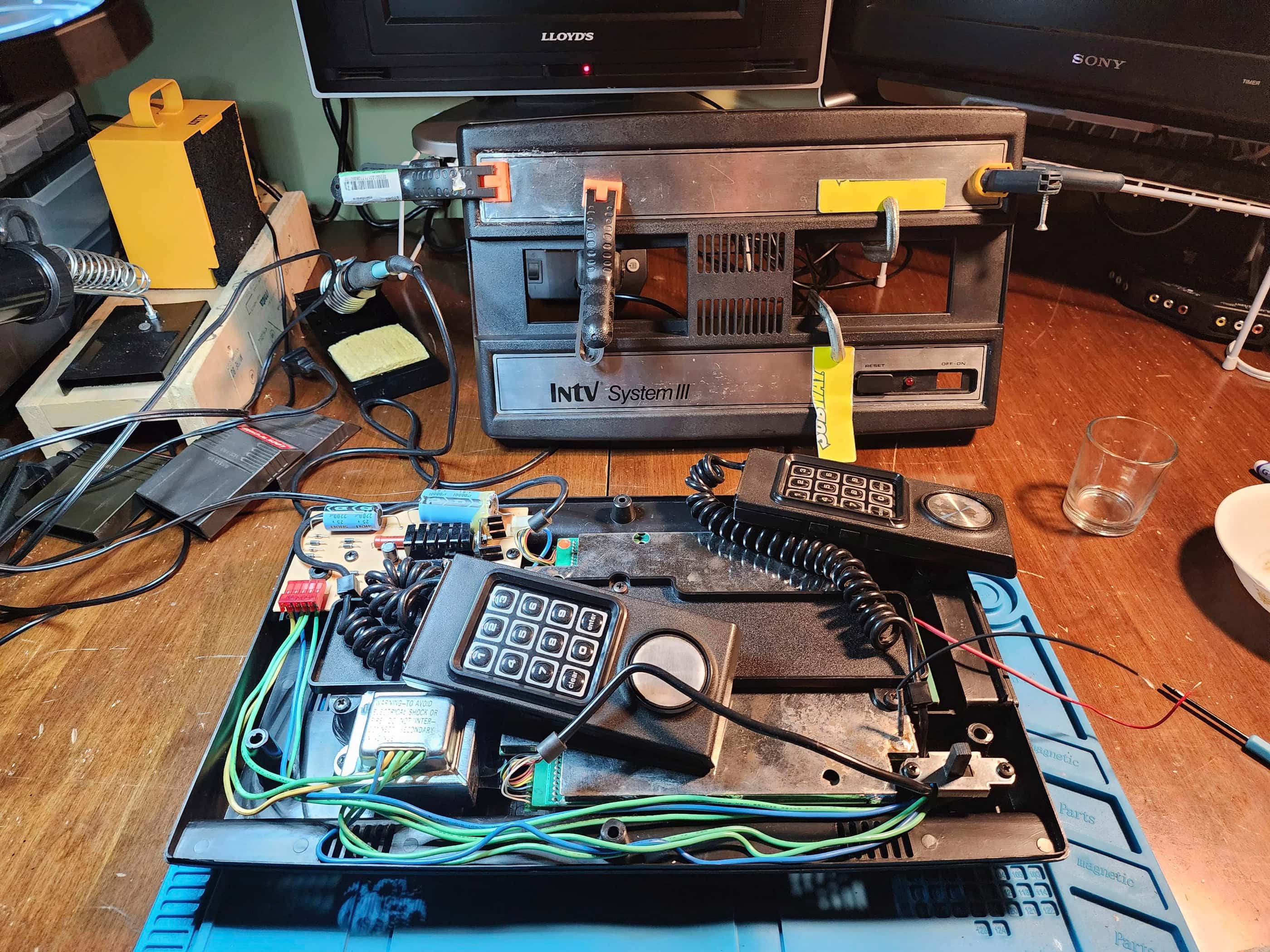
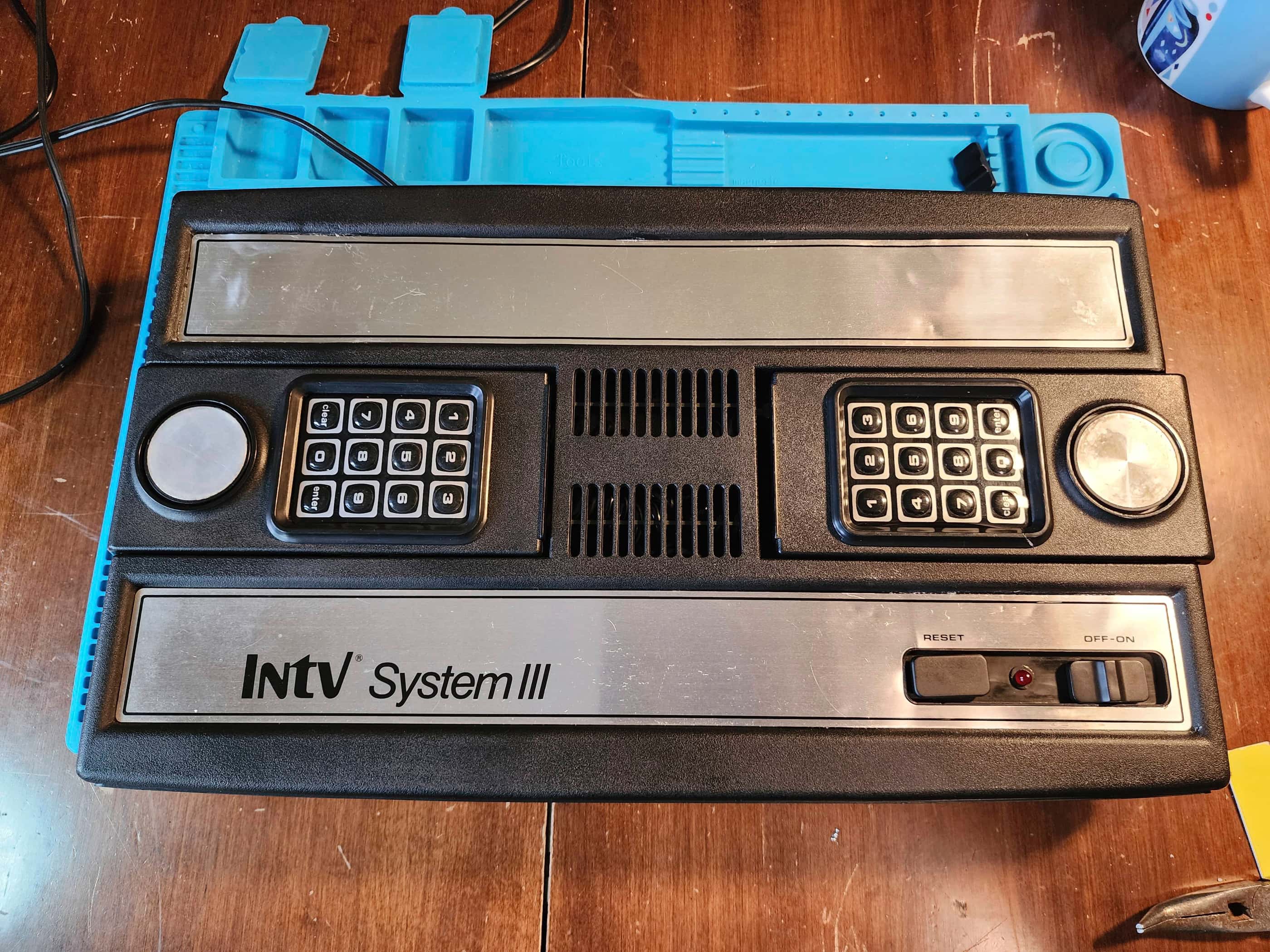
Project Details: This came as part of a cheap lot with my Atari 2600 “Vader”. At the time, I didn’t realize that these consoles are somewhat hard to find, despite being remakes of the original Intellivision. This particular unit came to me as untested and like the 2600 Vader, had been sitting in storage for a couple decades. It was dirty and the metal label strips on the top of the case were not in great shape. One controller was missing its keypad but the other keypad was in decent shape. When I turned the unit on, it had no trouble with graphics or sound which was also a bonus, but it did have trouble powering up on a consistent basis. The controllers however, had significant issues. I proceeded to take the unit apart and give it a thorough cleaning as it was very dirty. I also disassembled, cleaned, applied dielectric grease, and reassembled the power switch which fixed the power issue. I then moved on to disassembling and cleaning the controllers to see what could be salvaged. I ended up being able to create two functional controllers and moved the good keypad onto the left controller. I put everything back together as a functional system in the hope that I’d one day find another INTV System III that I could use for its mylar keypad(s) – or if it was better, use this as the parts system. Well, that day arrived when I found INTV System II #2 and I was able to harvest a new set of keypads. As the top cover of #2 was also in better shape, I also swapped these.
I tried to heat and remove the metal strips and while I partially succeeded, I did not like the end result. 😑 It still looks better than the original top cover, but it is super easy to dent / crease these things. It is however, a fully working system.
Parts & Products Used: 99% isopropyl alcohol; Chemical Guys Natural Shine; dielectric grease; E6000 adhesive
INTV System III (#2)
Years (1985-1990)
Interesting fact: In addition to re-releasing the original Intellivision, INTV also published 21 new Intellivision cartridges. (source)
Condition When Acquired: Non-Functional
(DOA)
Current Condition: Active Project / Parts System
Project Details: This unit popped onto my radar because I was looking for a System III that I could use for its mylar number pads to finishing restoring INTV System III #1. It was DOA and for this reason, it was very cheap to acquire. On arrival, I tried powering it up and though the power light came on, the system was stone dead. My first inclination was to fix it, but because I bought it to be a parts system, I made that my priority. As the console’s top cover was in much better better shape and because it had better mylar number pads, I decided to perform a swap. Other than that, I haven’t touched the unit to try and fix it. One day….
Parts & Products Used:
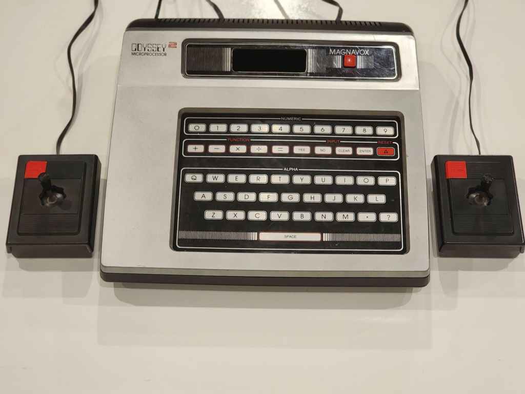
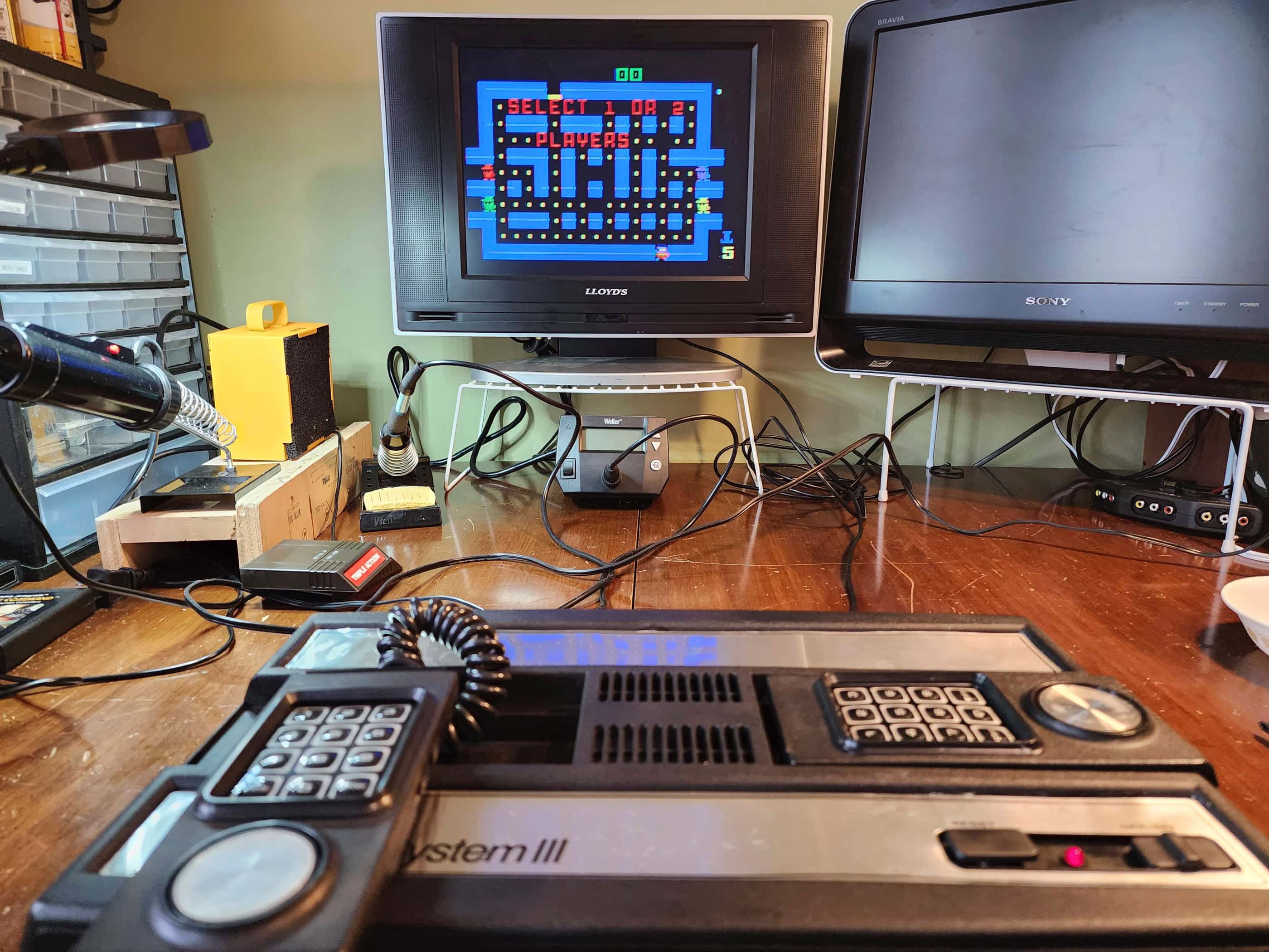
Magnavox Odyssey 2 (#1)
Years (1978 – 1984)
Interesting fact: After pioneering home video games in 1972 with the Odyssey, Magnavox entered the cartridge-based console market with the Odyssey 2. It contained Intel’s first mass-market microchip, the 8048 and included a membrane keyboard that was used to sell it to parents as more than just a gaming system. (source)
Condition When Acquired: Partially Functional – controller issues
Current Condition: Fully Functional


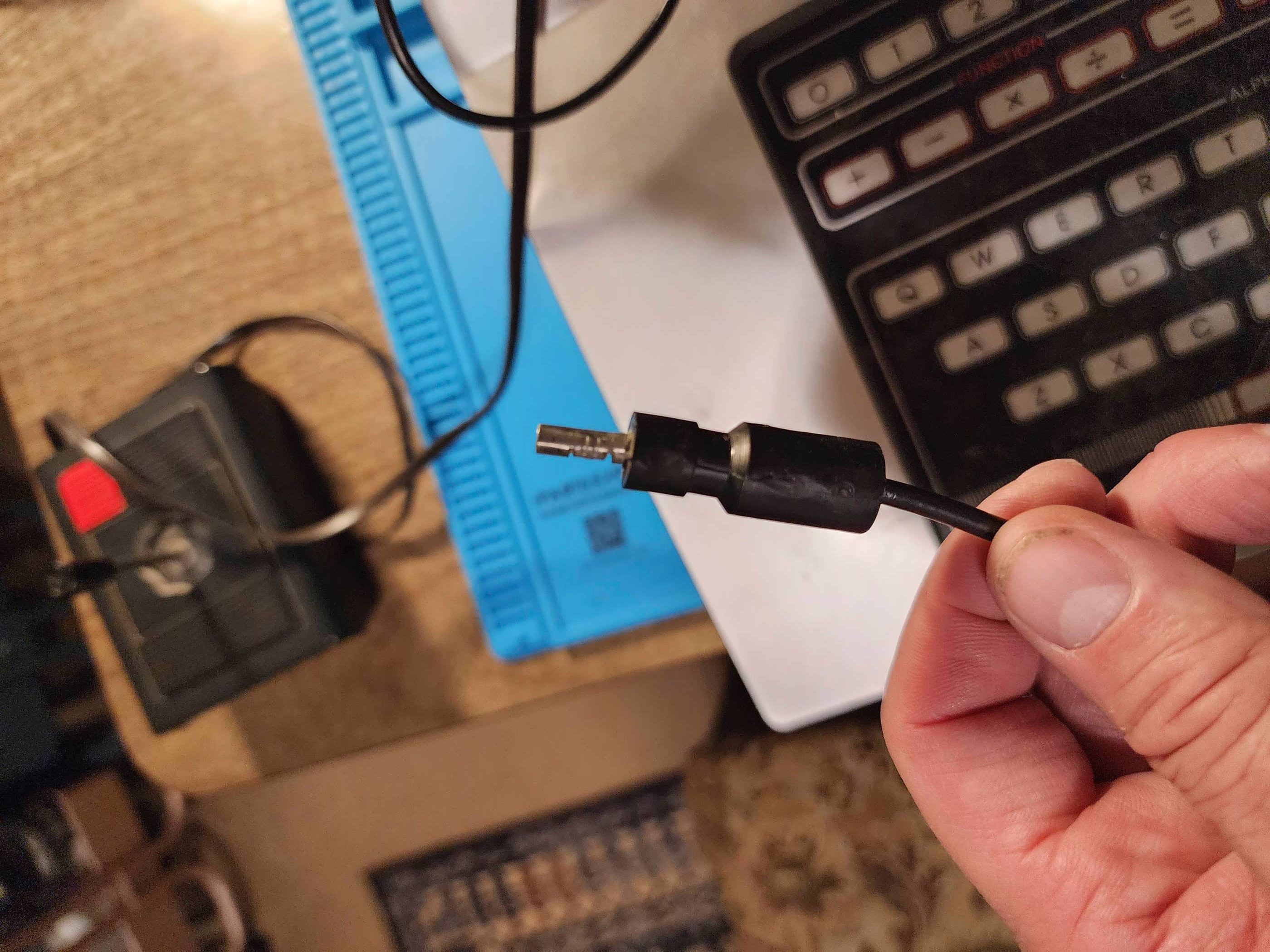
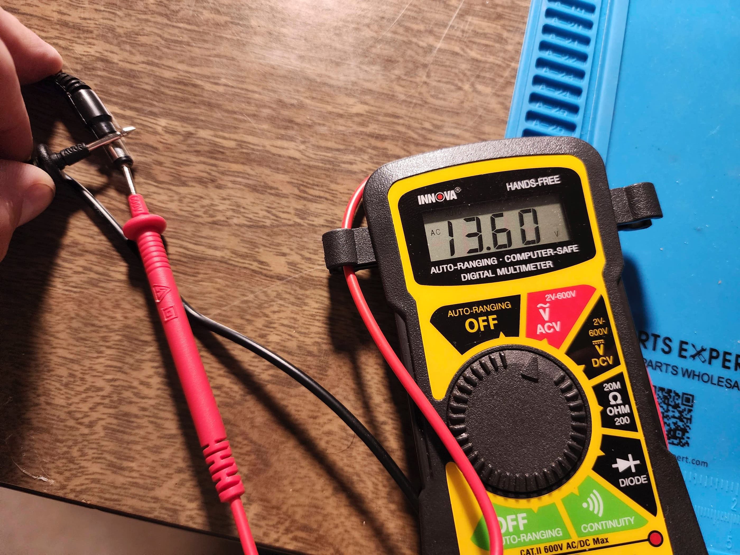
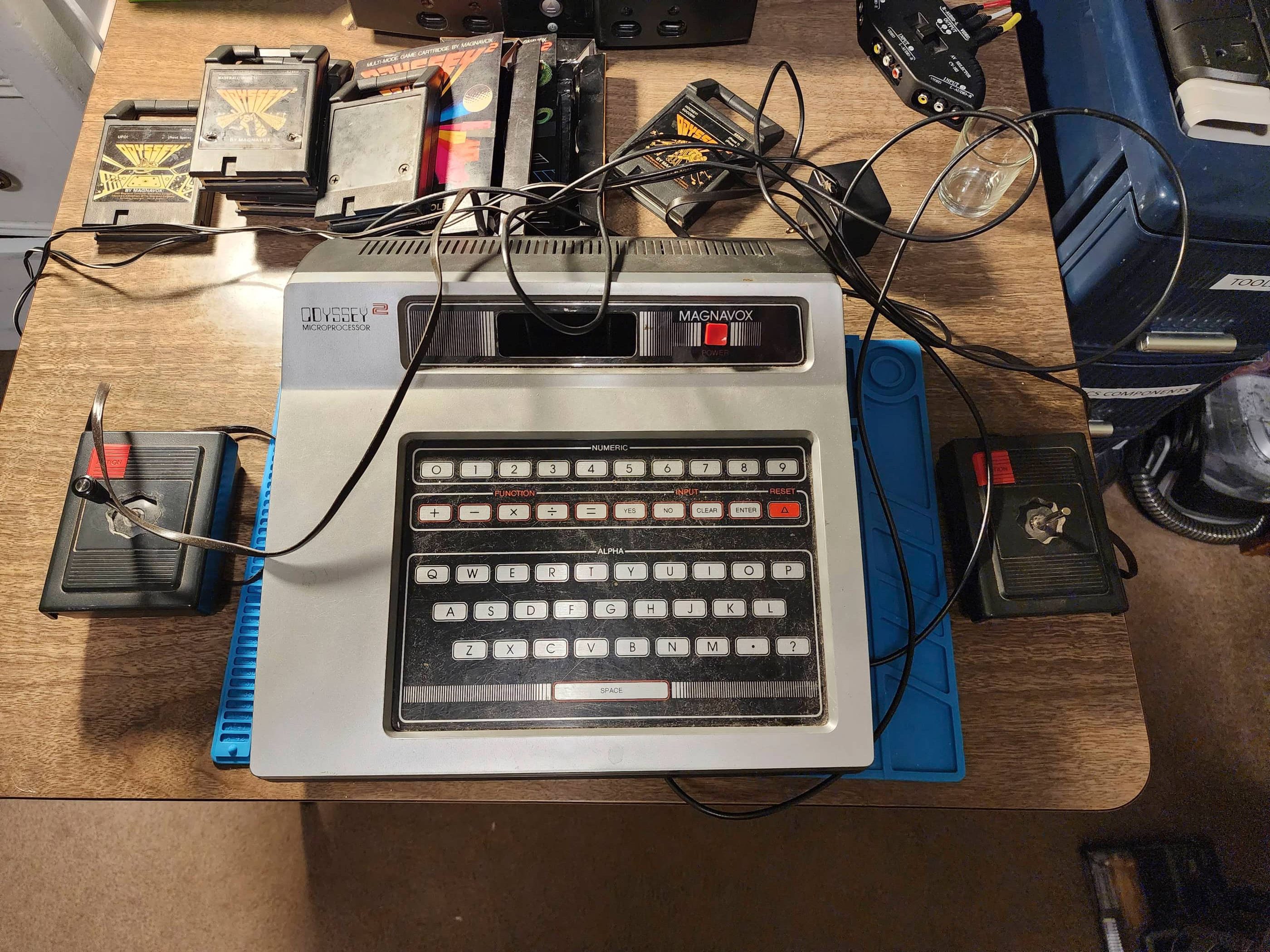
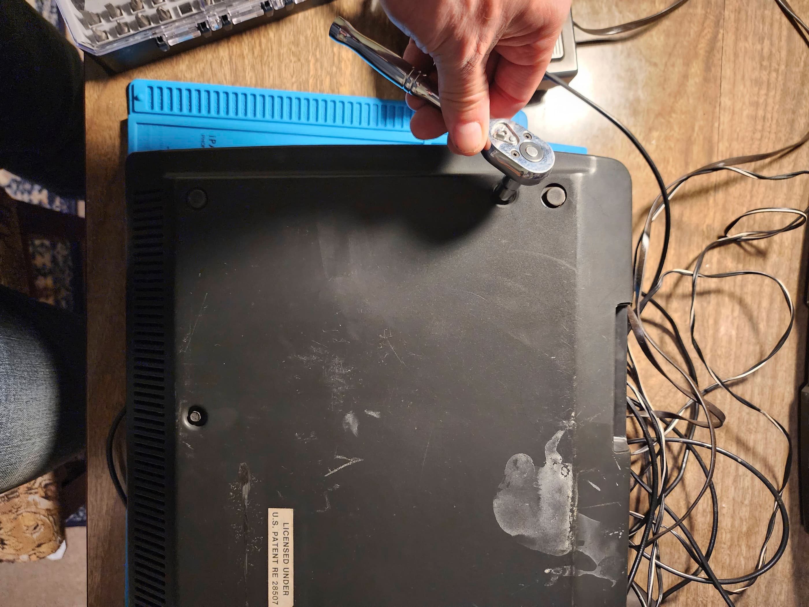


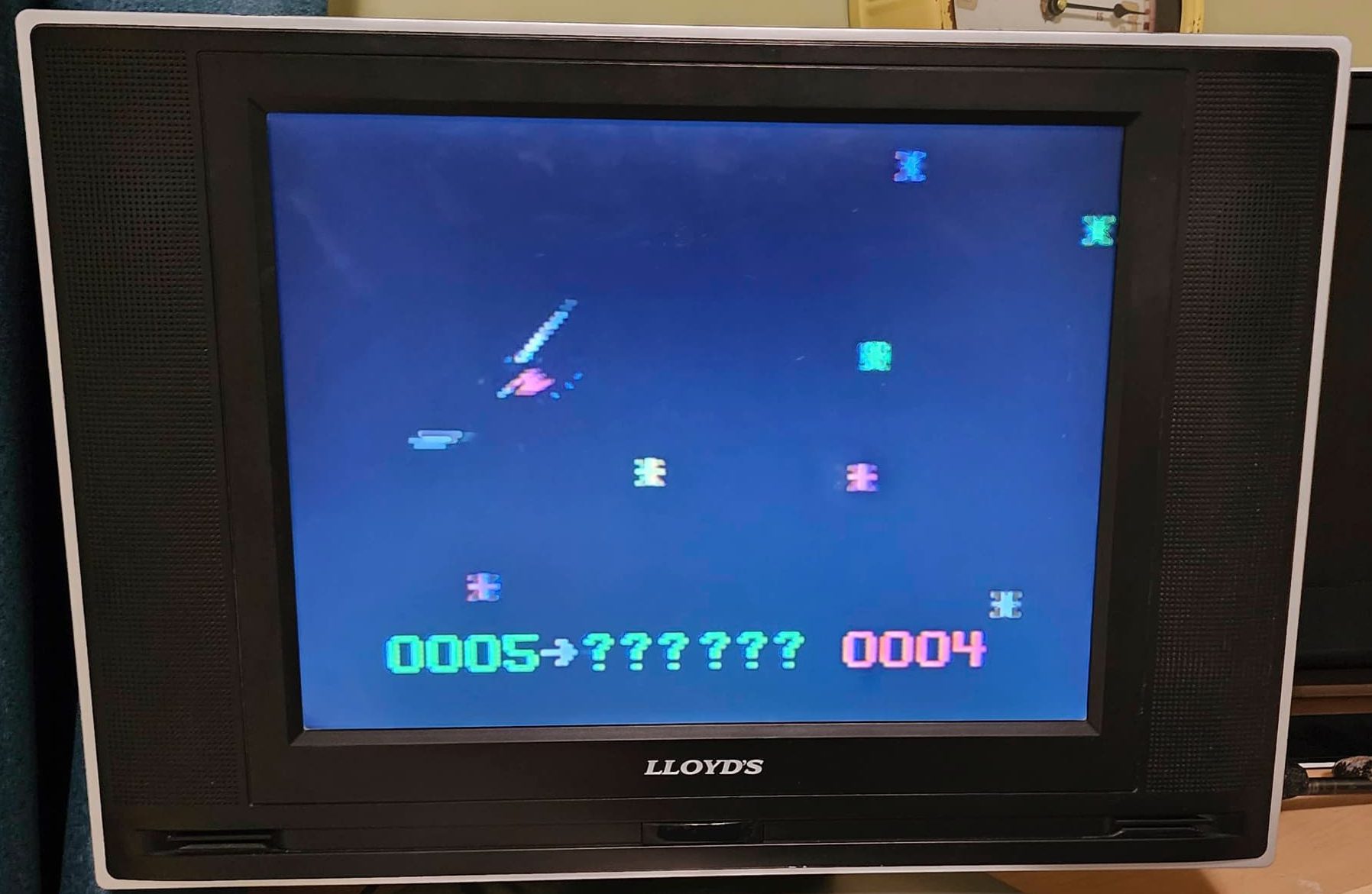
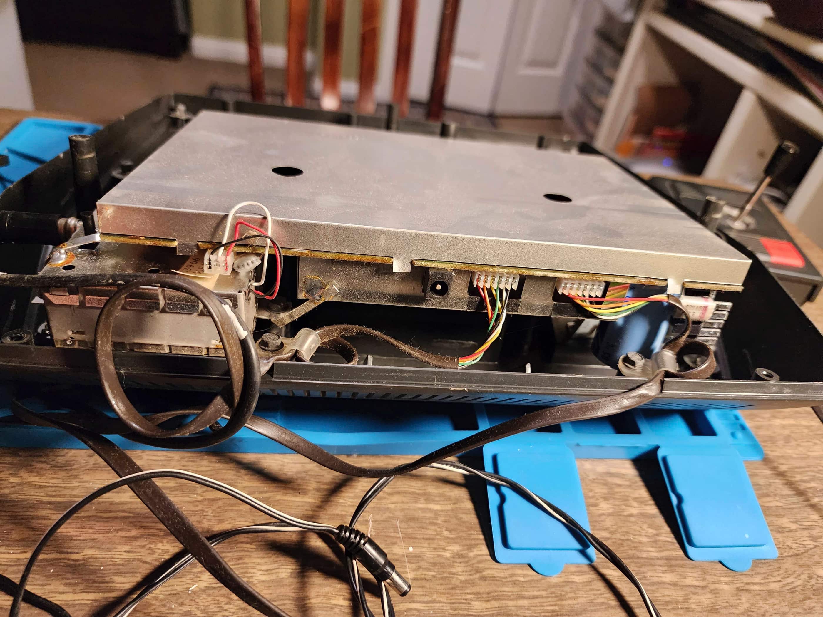
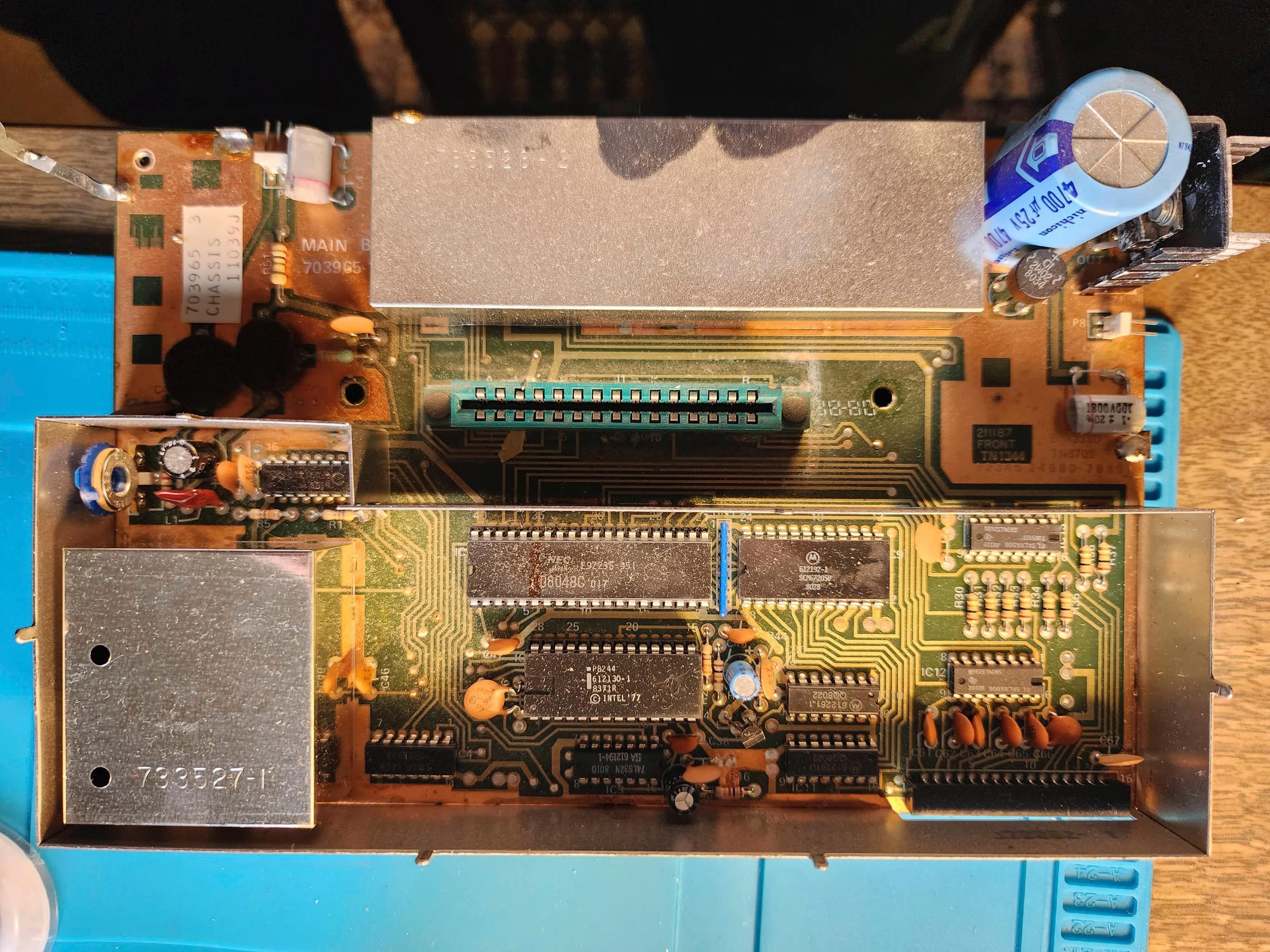
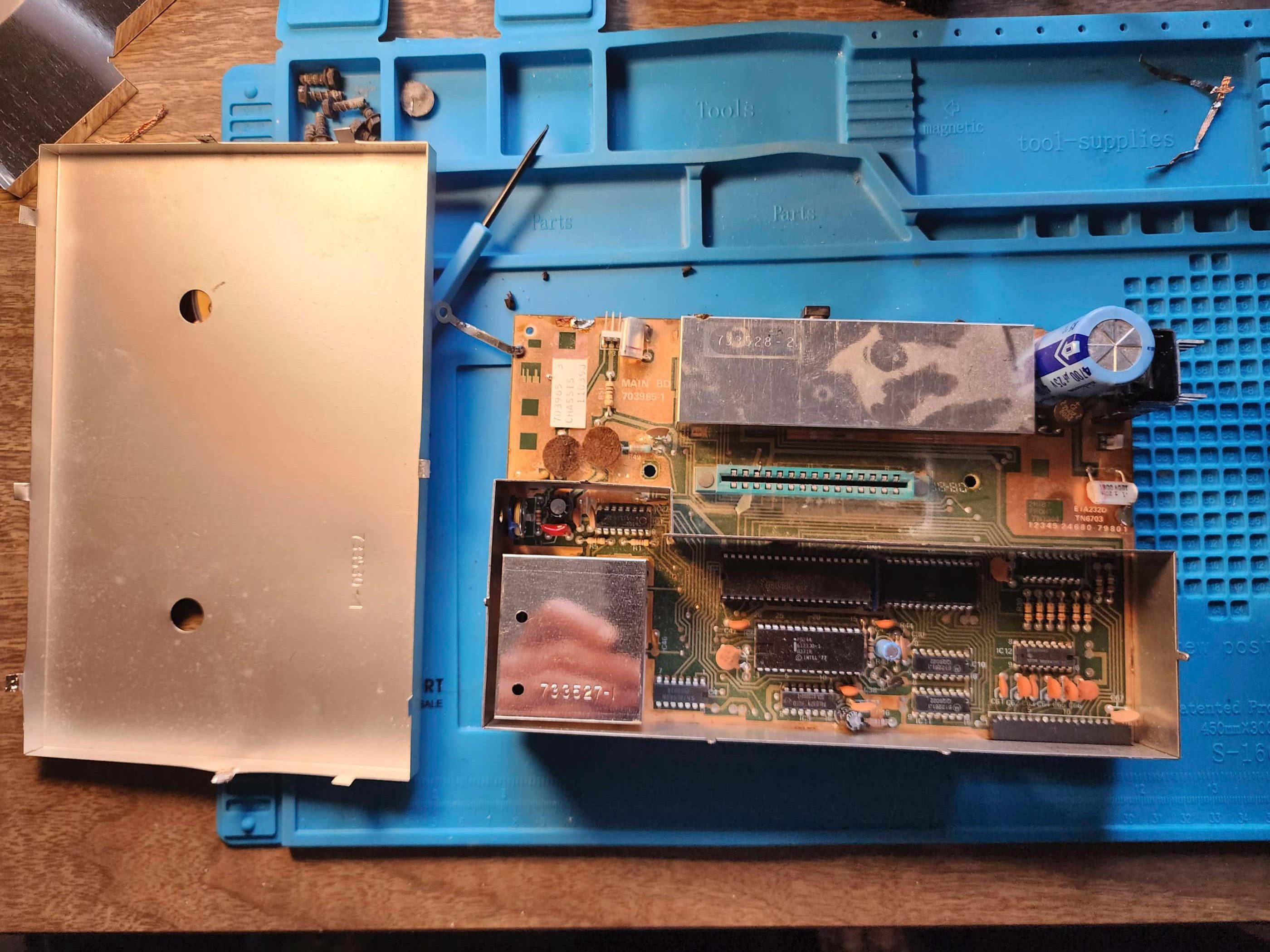


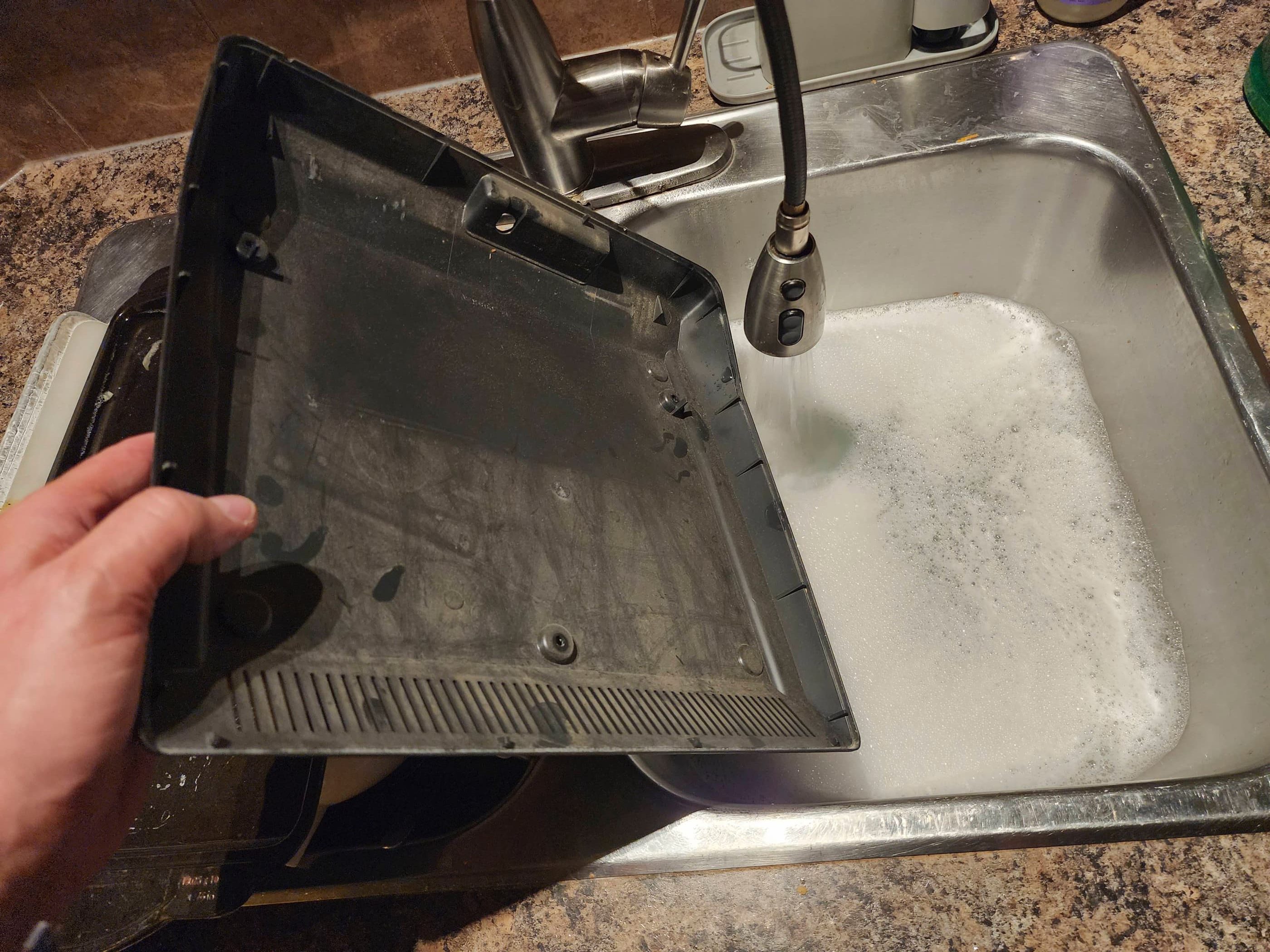
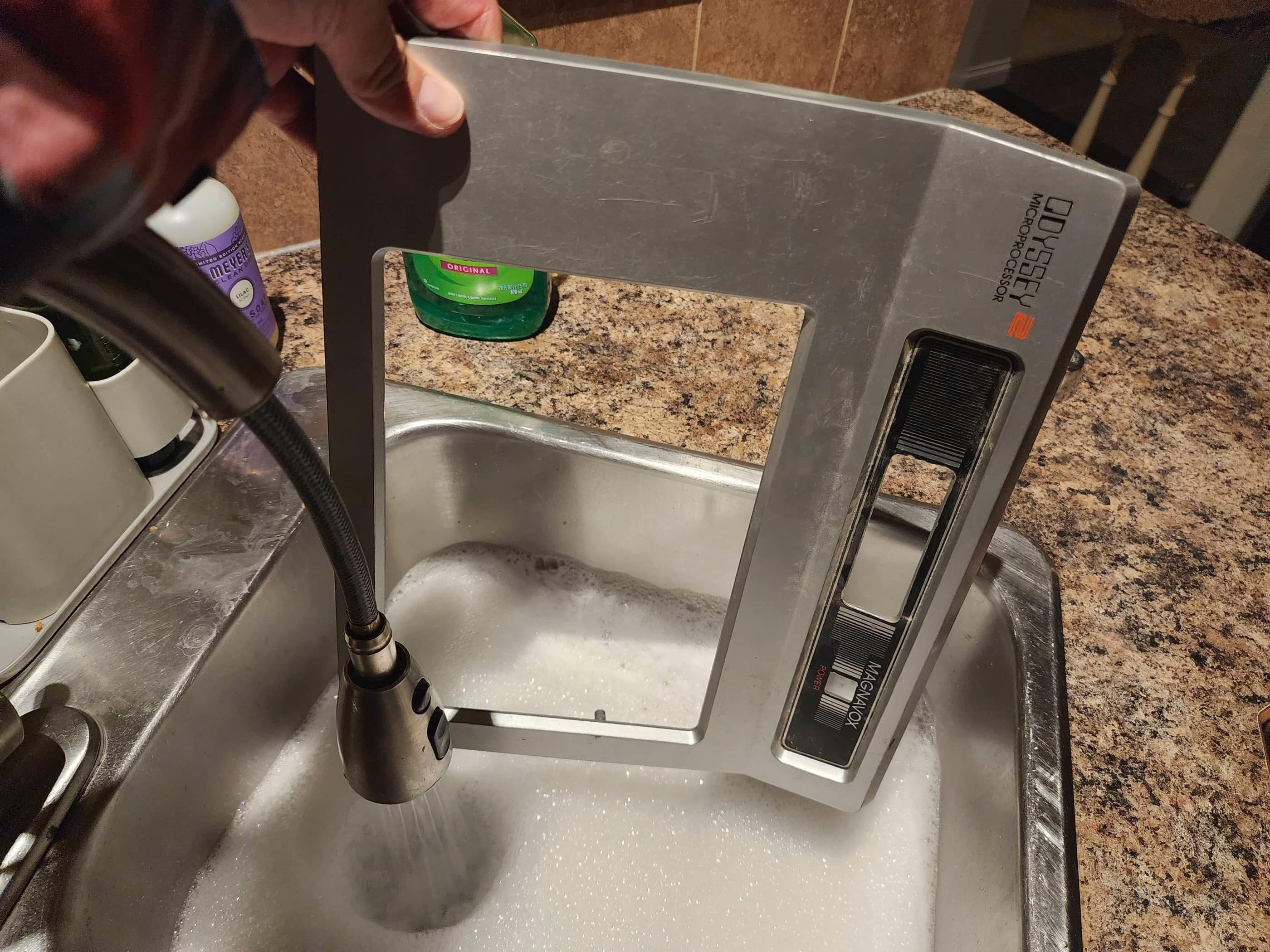

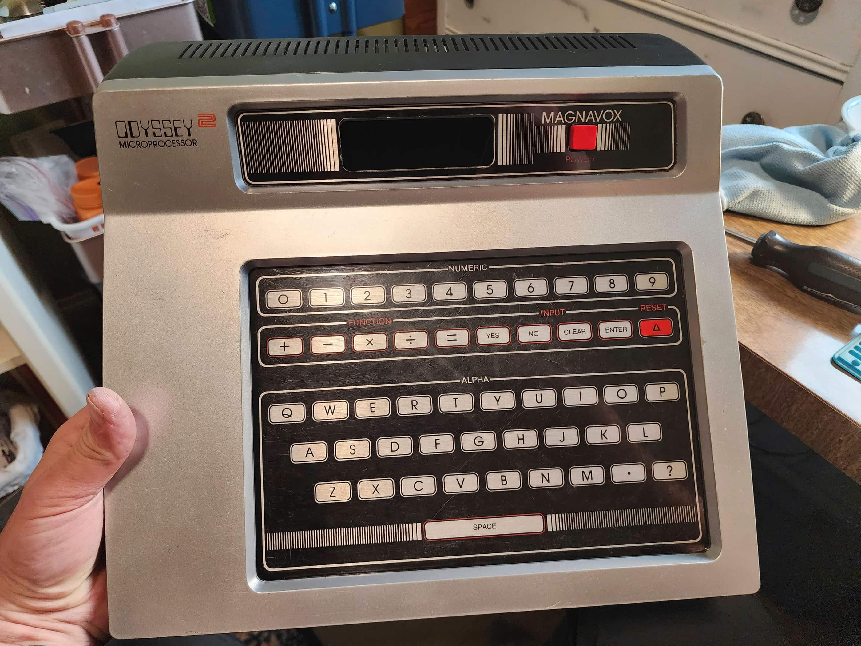
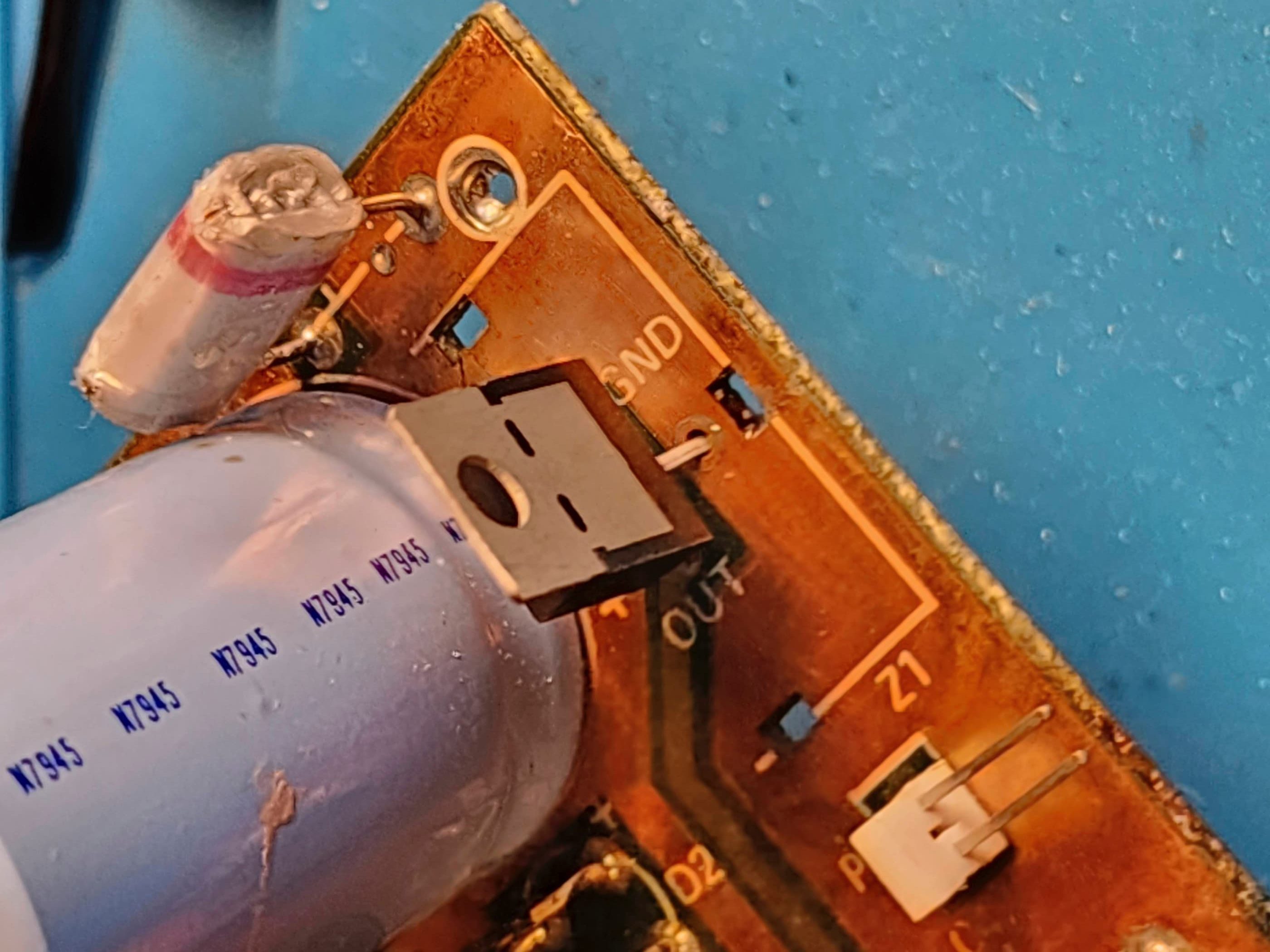
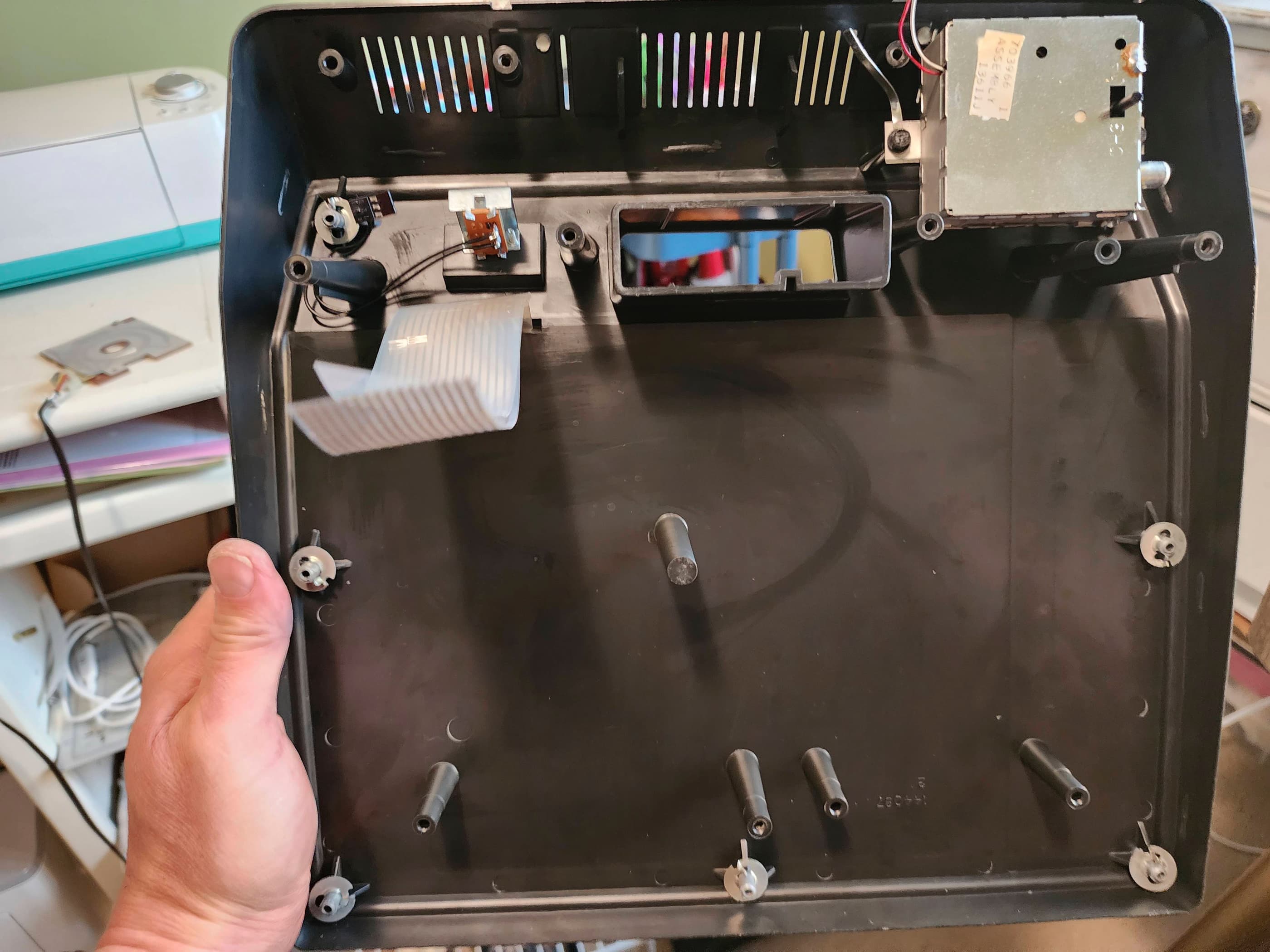


Project Details: We found this at the local thrift store in its original box along with 8 games. It even had some of the original documentation. The weird end of the RF cable was something that I’d never seen before, and after doing some digging, discovered that only the early models of the system used these. Not having the mated switch box, meant that I would have to put in a new RF cable, which I did. After confirming with a multimeter that the AC adapter (11.5 VAC) was functional, I proceeded to test the working status of the unit. Surprisingly, it worked; though the joysticks had little-to-no functionality. I then got to work on trying to desolder the RF shielding. Holy cow! 😳 What a nightmare! I ended up getting the key pieces off, but left the rest attached because it was taking way too long and I was in danger of lead poisoning. 😂 The weird thing about the Odyssey 2, is that the RF box is separate from the main board and there are a couple ground straps that have to be desoldered before you can remove the main board before the RF box. For testing, I had to run alligator clips from the board to the box for grounding to ensure that I could get an output.
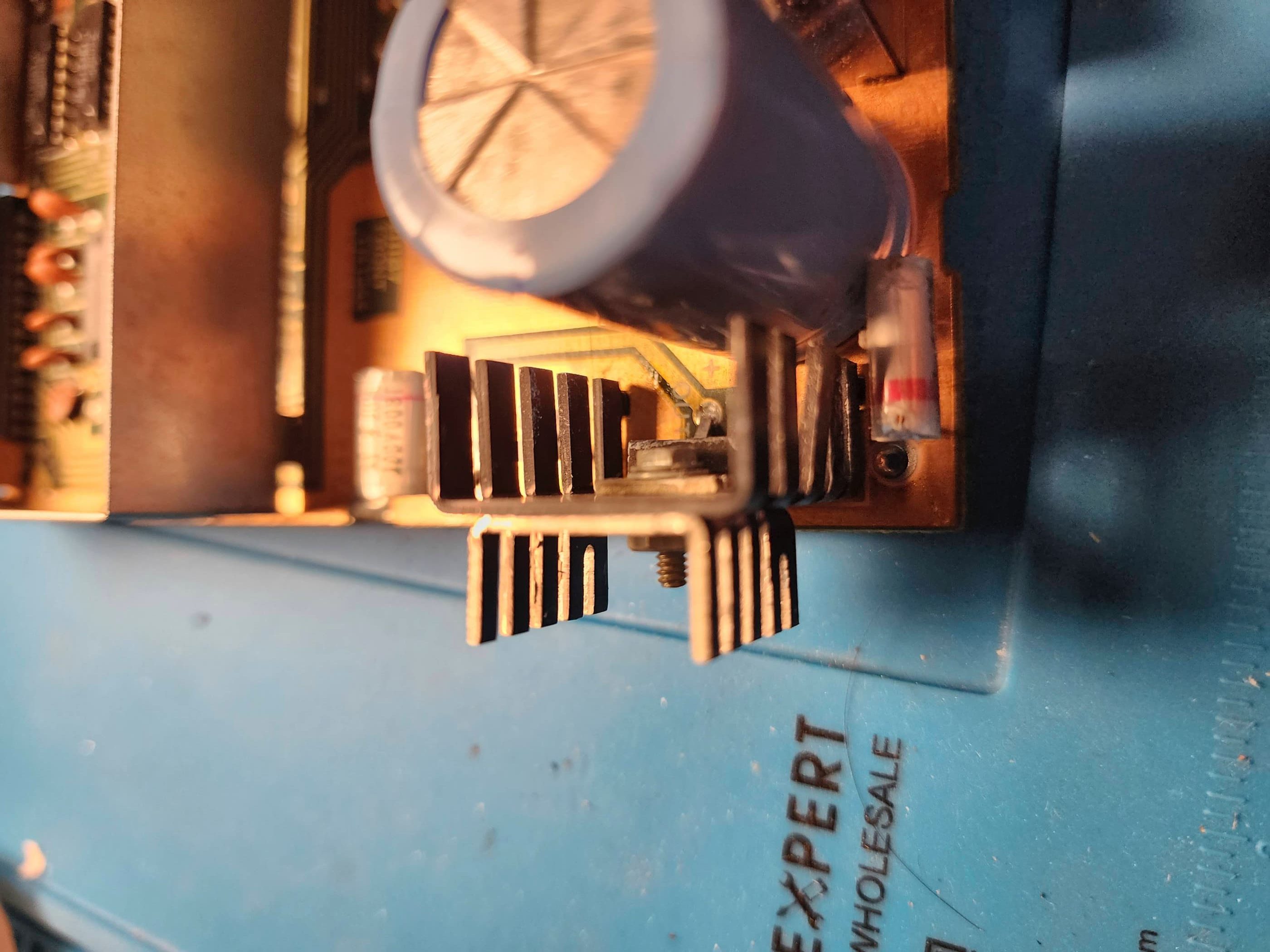
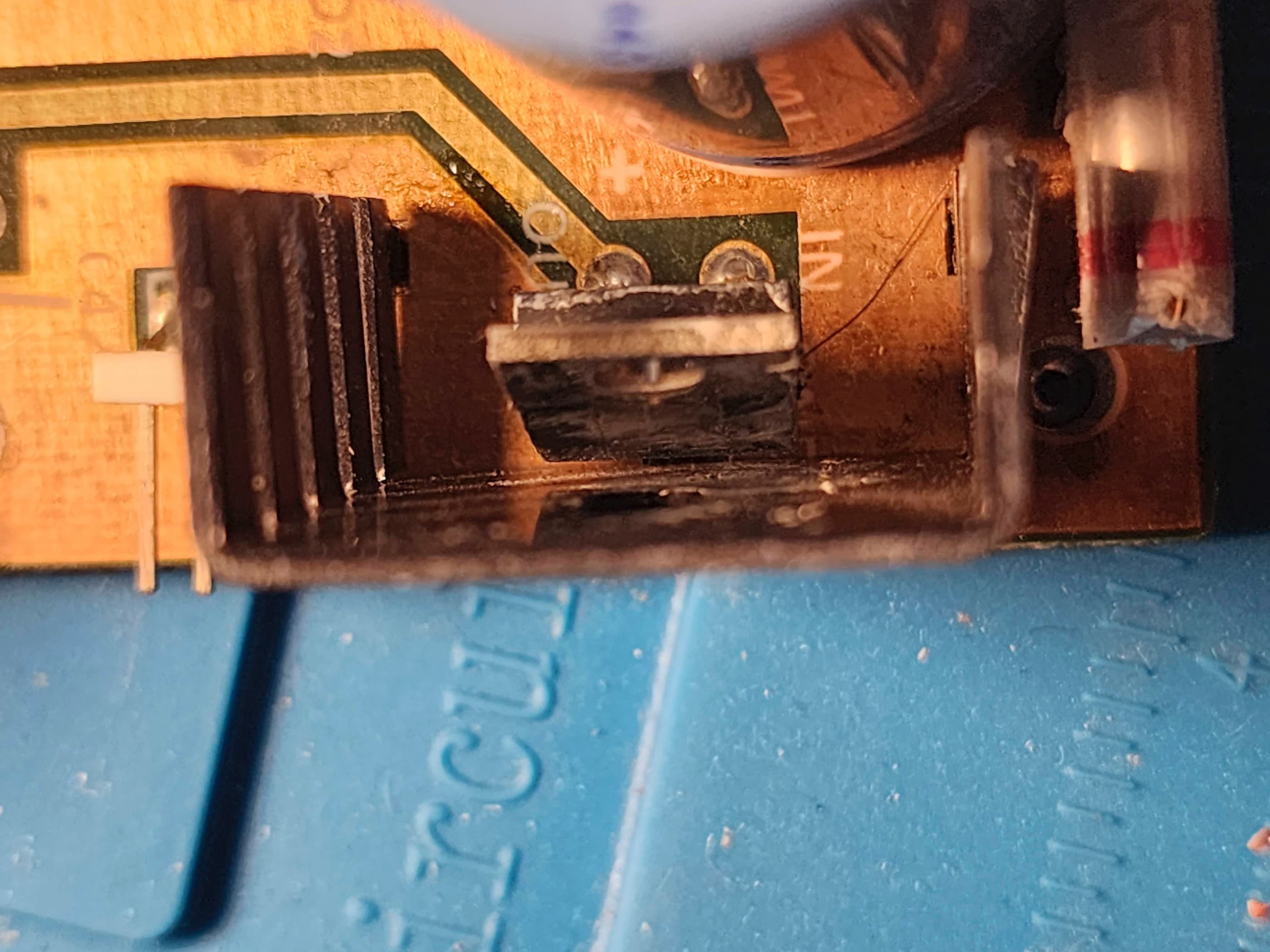
As the machine was working, I decided not to re-cap it, but in the process of putting new thermal grease onto the voltage regulator and heatsinks, I bent the regulator too far forward and wrecked it. Doh! 🤪 This is because the ground pin is set farther back on the board and is not lined up with the in / out pins. Fortunately, I keep a healthy supply of 7805 5v regulators on hand and it only took a couple minutes to replace it. I also disassembled the power switch, cleaned the dirty contacts, applied dielectric grease, and reassembled the switch. Unfortunately, I put the contact strip in the wrong slot and then spent several minutes trying to figure out why the machine didn’t turn on. Doh! 🤪 After I figured it out and fixed the problem, the machine turned on without issue.
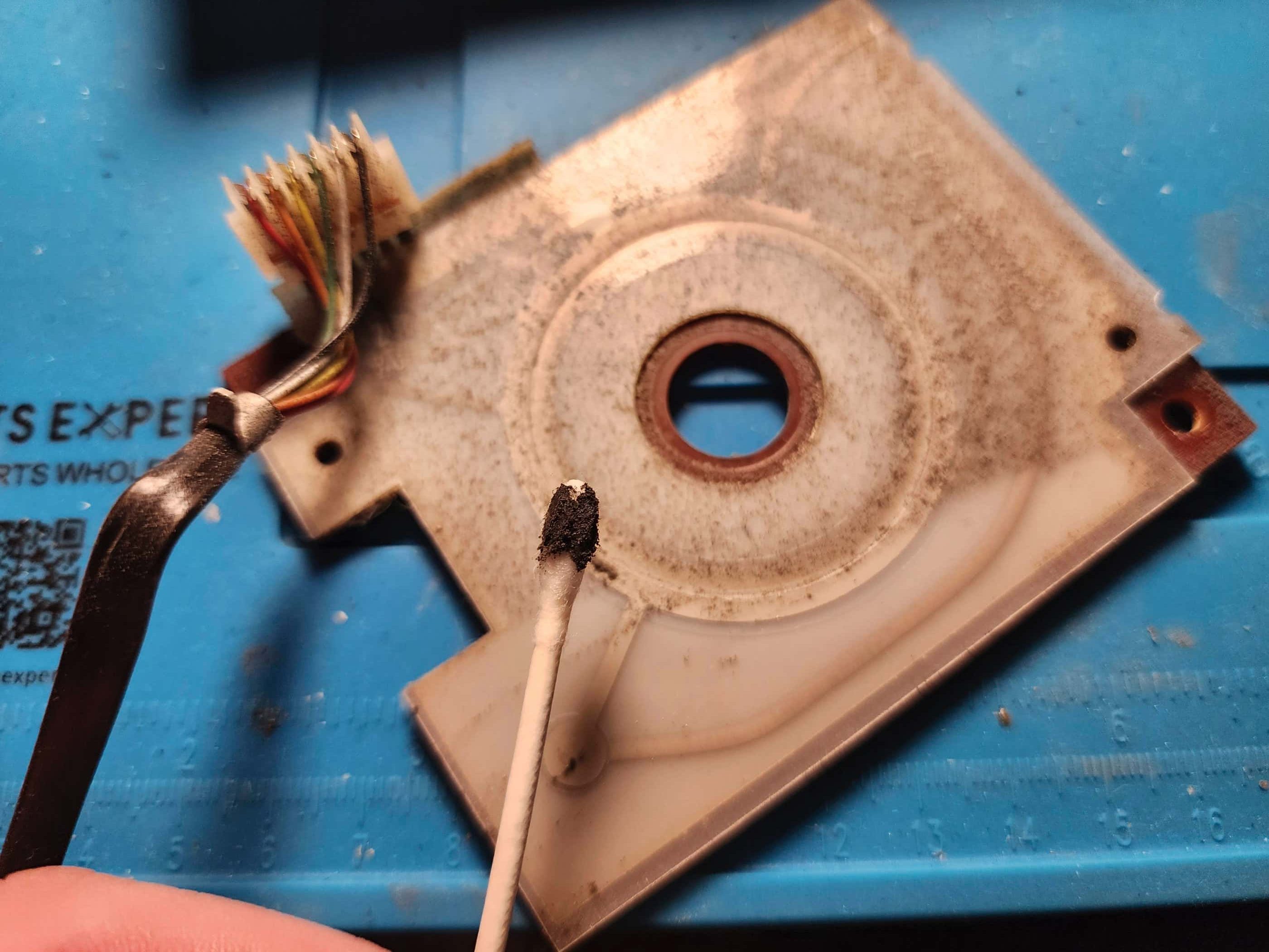
After a detailed cleaning I moved on to try and fix the controllers. When I opened them up, I was shocked at how dirty the flex circuits were. I spent a long time trying to clean them, hoping that this was the issue, but the dark lines I could see under the film made me conclude that there were continuity issues that couldn’t be fixed. My multimeter then confirmed this to be true. I reassembled the controllers but could not get them to work at all. This meant my only other option was to find replacement parts which meant waiting until MO2 #2 arrived. Once on hand, I swapped the controllers over and tried out some games. The left controller now worked without issue; however, the right controller was unresponsive and even after reseating it onto the board, it still did not work. To determine if it was a controller or board issue, I swapped the controllers to opposite sides and this immediately fixed the issue. To me, this was weird because I simply put the left controller from the MO2 to the left port on the MO1 and likewise for the right. However, swapping them fixed the problem and to finalize their placement, I adjusted the stress release slack on the cord for each controller. I reassembled the unit and gave it a final test with a variety of games. It passed with flying colours. I now have a fully functional MO2.
Parts & Products Used: 99% isopropyl alcohol; Chemical Guys Natural Shine; dielectric grease; thermal paste; 7805 +5v regulator (1); replacement RF cable;
Magnavox Odyssey 2 (#2)
Years (1979 – 1984)
Interesting fact: K.C. Munchkin was a Pac-Man-like game that became a bestseller for Magnavox. Atari held the home rights to Pac Man but Magnavox beat them to market with Munchkin. Atari sued and lost, but the ruling was overturned in another court and Magnavox had to stop selling what had become the Odyssey 2’s most popular game. (source)
Condition When Acquired: Unknown
Current Condition: Active Project / Parts System
Project Details: I bought this on the cheap to use as a parts system for MO2 #1 – in particular, its controllers. The seller said that it played games but the keyboard didn’t work, which made me a little suspicious because normally you need to make a selection on the keyboard to get past the initial game screen. Maybe they just popped in the cartridge, turned it on, and when the selection screen appeared, that was enough to say it was working. Of course, I bought this unit for its controllers and this is what I really needed to work. Since swapping the controllers, I haven’t touched this system but one day I’ll get around to it…
Parts & Products Used: None yet
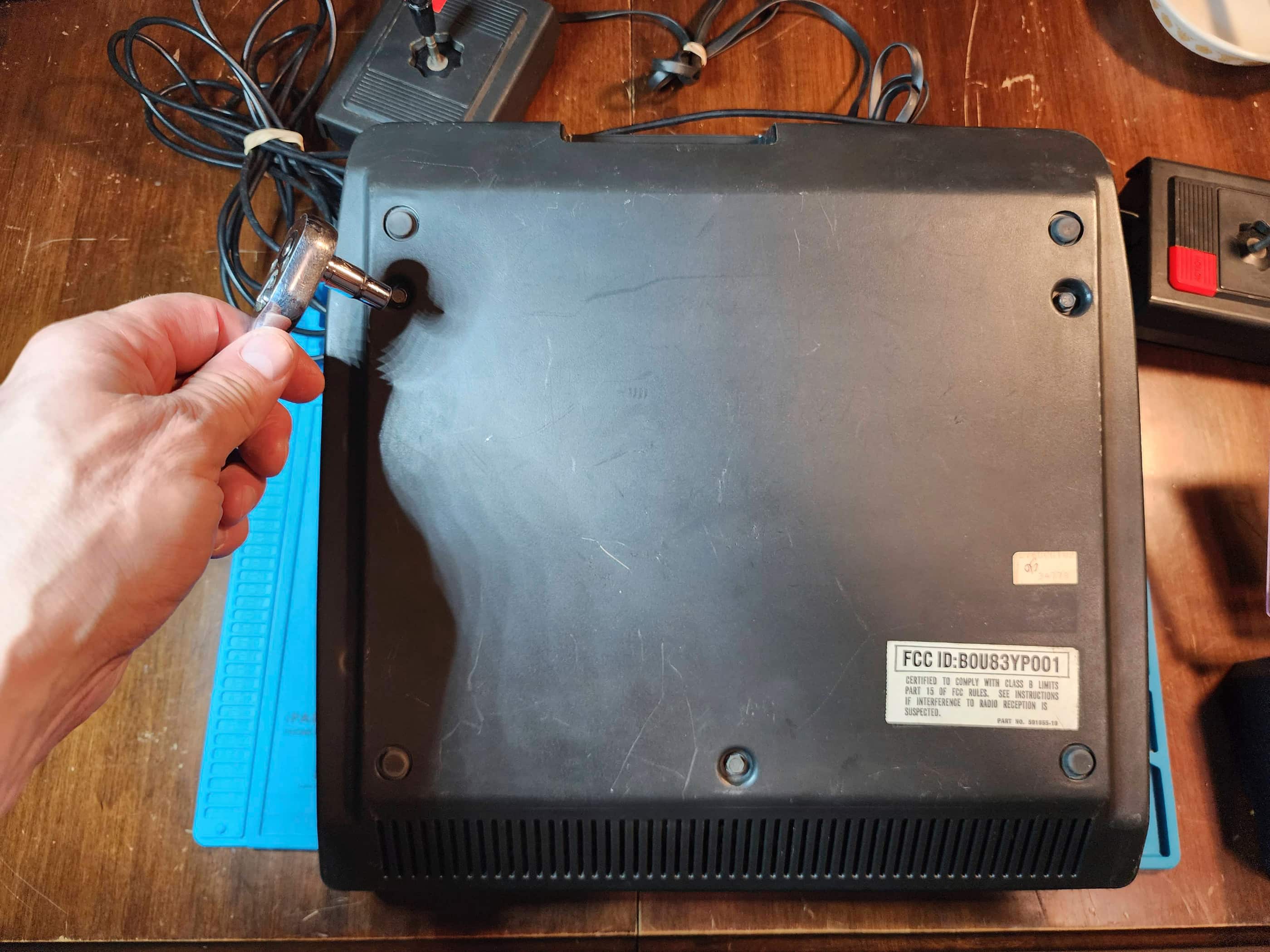
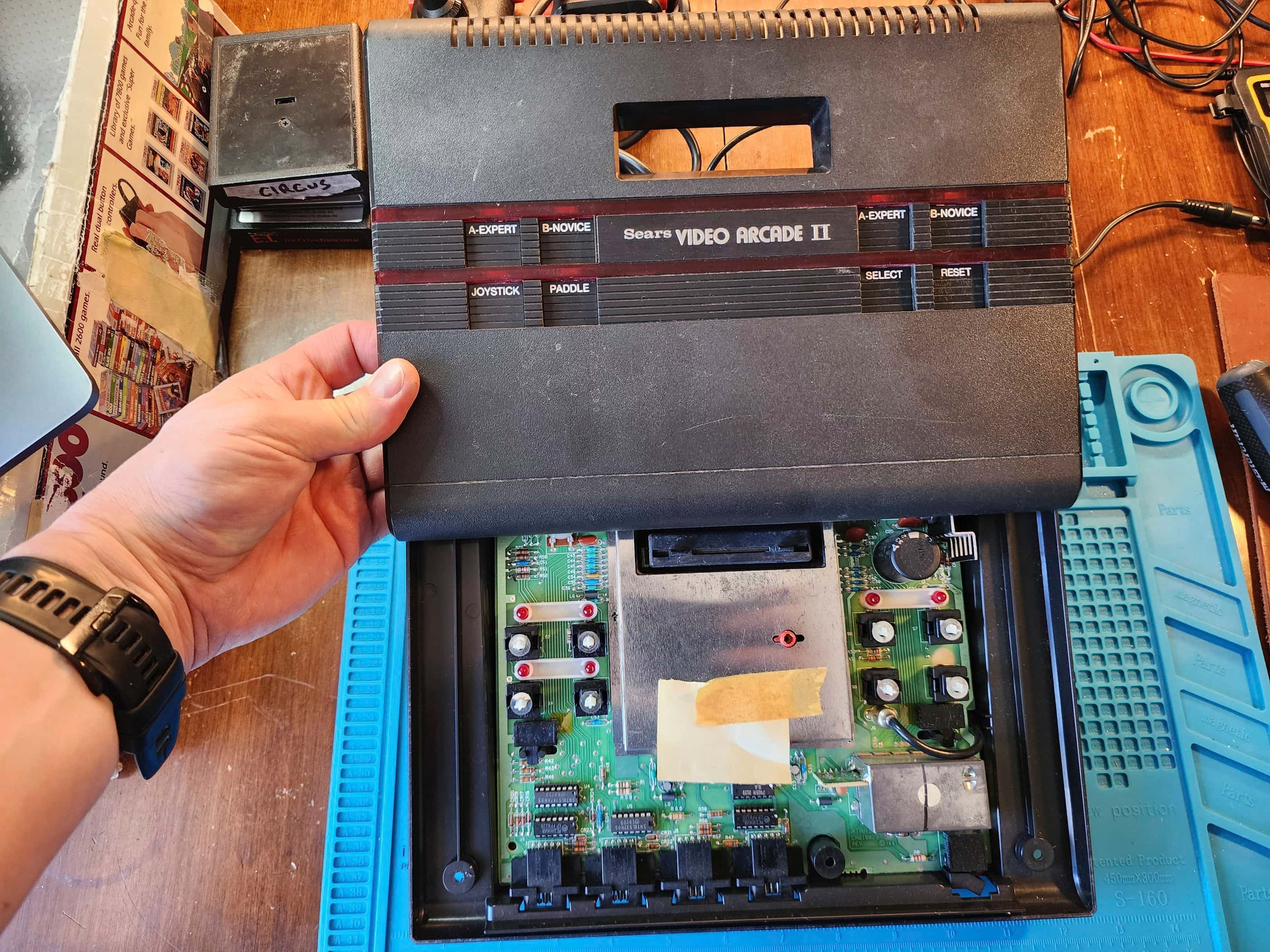
Sears Video Arcade II (Atari 2800)
Years (1983-1984)
Interesting Fact: While video games were booming in North America during the late 70s and early 80s, Japan was surprisingly behind the curve. In 1979, Atari and Japanese developer, Epoch, formed a partnership to try and capitalize on the popularity of Space Invaders by releasing a version of the Atari VCS called the Epcoh Cassette TV Game. (source) Unfortunately, this never caught on, so Atari decided to try again in 1983, this time with a re-design of the CX-2600 called the Atari 2800. Again, Japanese consumers failed to respond and with the subsequent crash of the video game market in 1983, the 2800’s planned release in North America was also scrapped. (source)
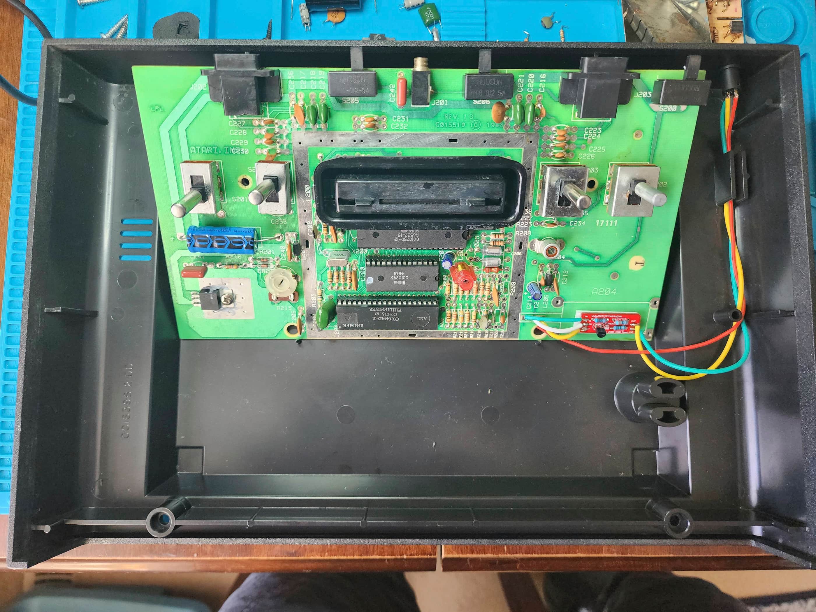
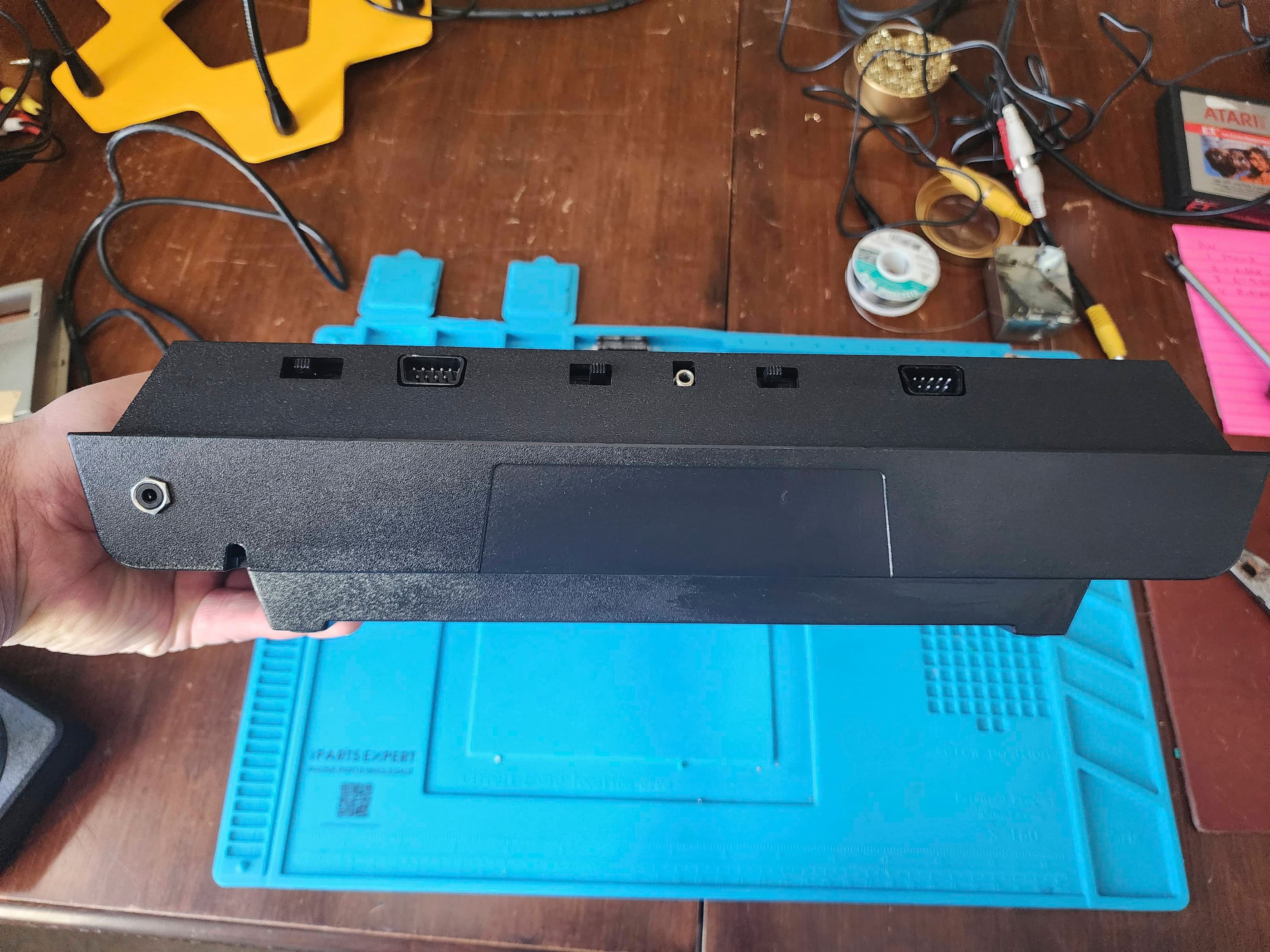
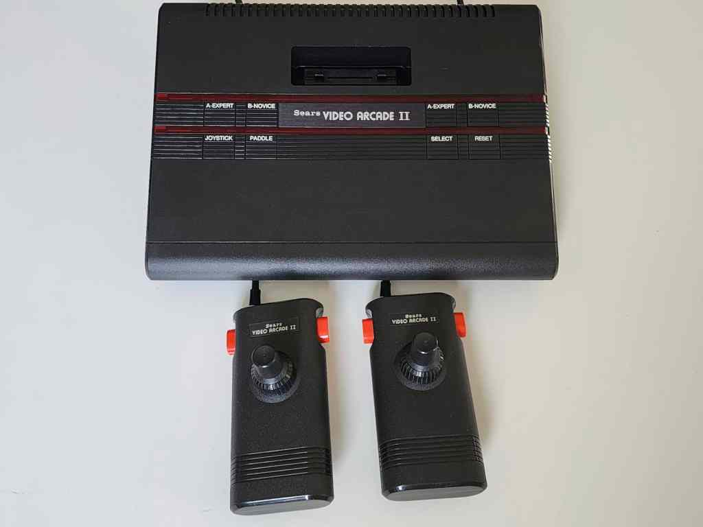
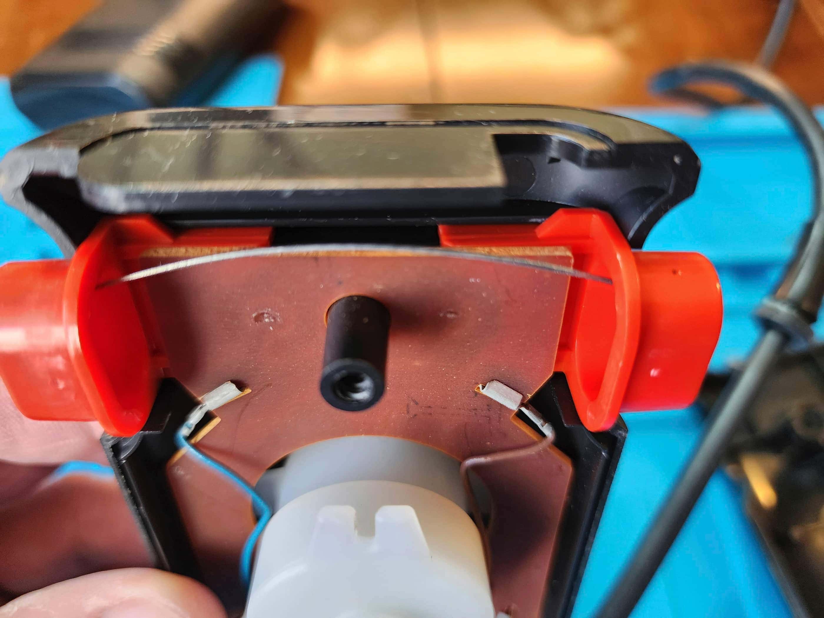
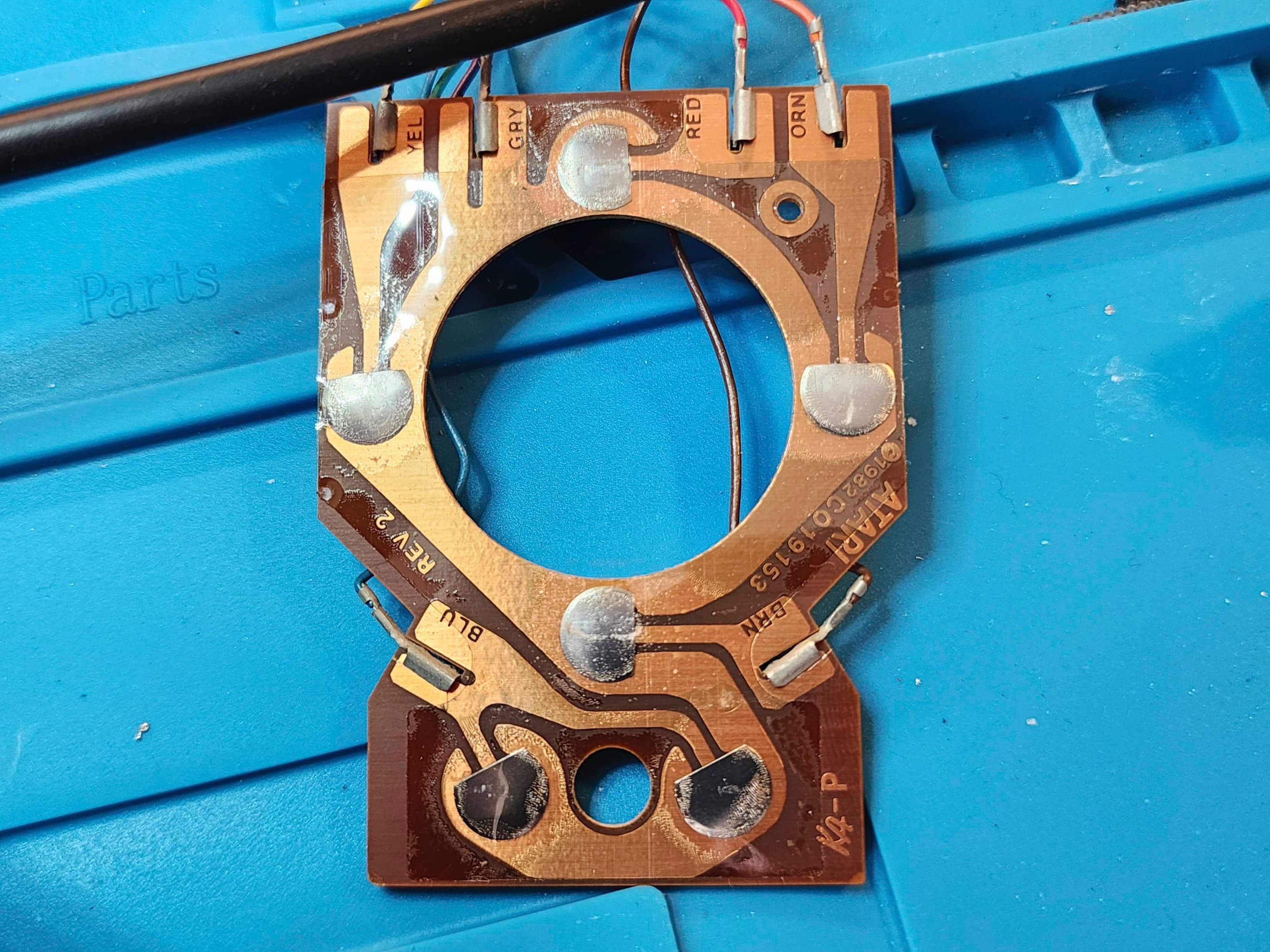
However, before this happened, Sears had begun selling the 2800 as the Video Arcade II, making it the only version of the Atari 2800 to be sold in North America. (source) Interestingly, the VAII / 2800 used a new case design that would eventually be utilized by Atari 7800 in 1986. (source) The VAII / 2800 featured 4 joystick ports along with new controllers that incorporated dual fire buttons and a unique joystick / paddle combination. Unlike the VCS and the 2600, the VAII / 2800 used a 9V AC to AC power adapter. Though it was compatible with all 2600 games, in Japan there were 30 unique titles that were released for it. (source).
Condition When Acquired: Fully Functional
Current Condition: Fully Functional


Project Details: When I saw this ‘untested’ console pop-up on Ebay for a great price, I couldn’t pass on the opportunity as these are somewhat rare to find. However, it did not come with a power adapter or with controllers, which meant that I also had to find a pair of controllers to go with it. That it could use a Ninetendo NES power adapter meant that I had this part already covered.
After purchasing the console from the east coast of the US, I was then able to find an ‘untested’ pair of controllers from Colorado. When everything arrived several weeks later, I was anxious to see what I’d gotten myself into.
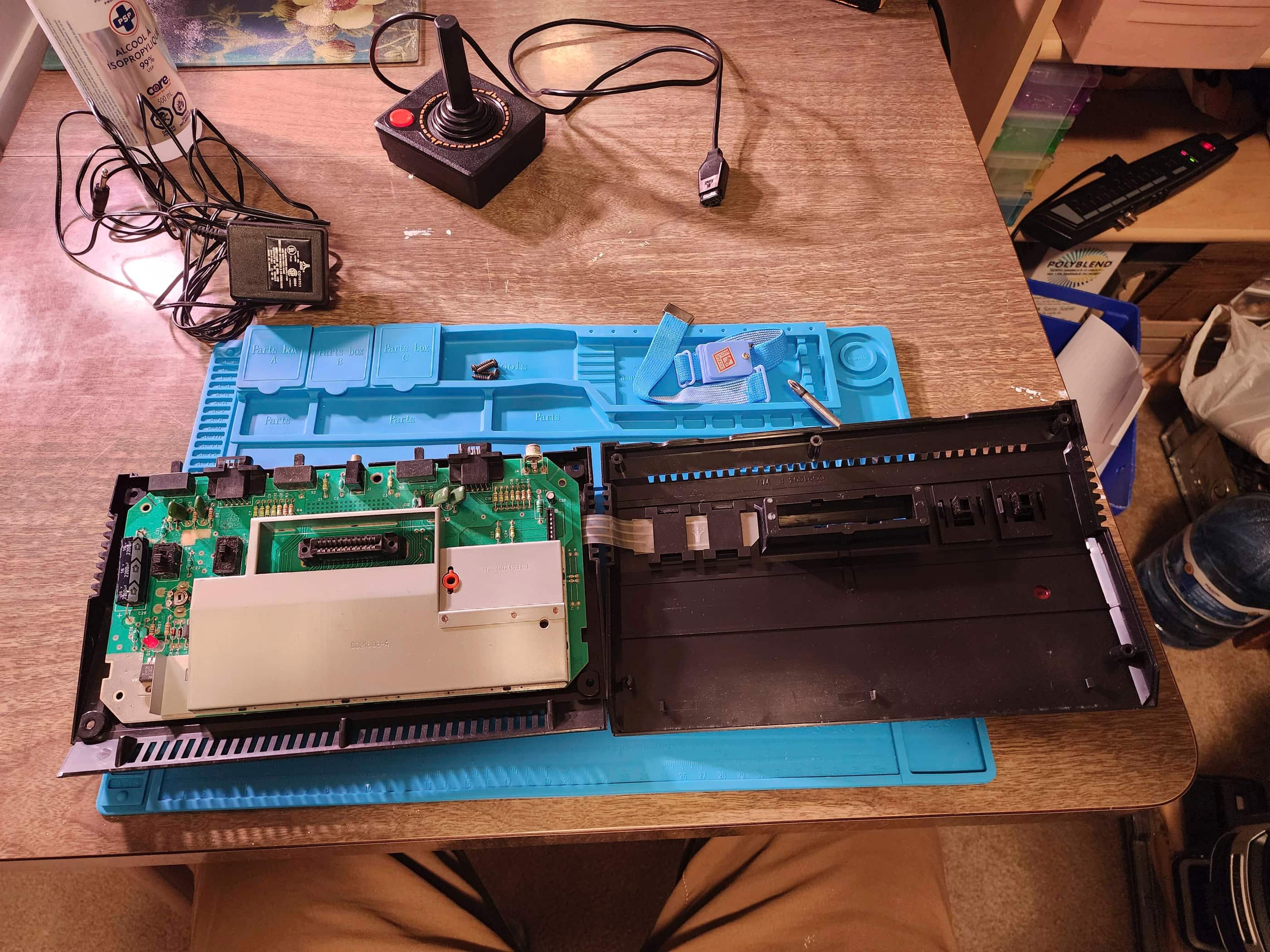
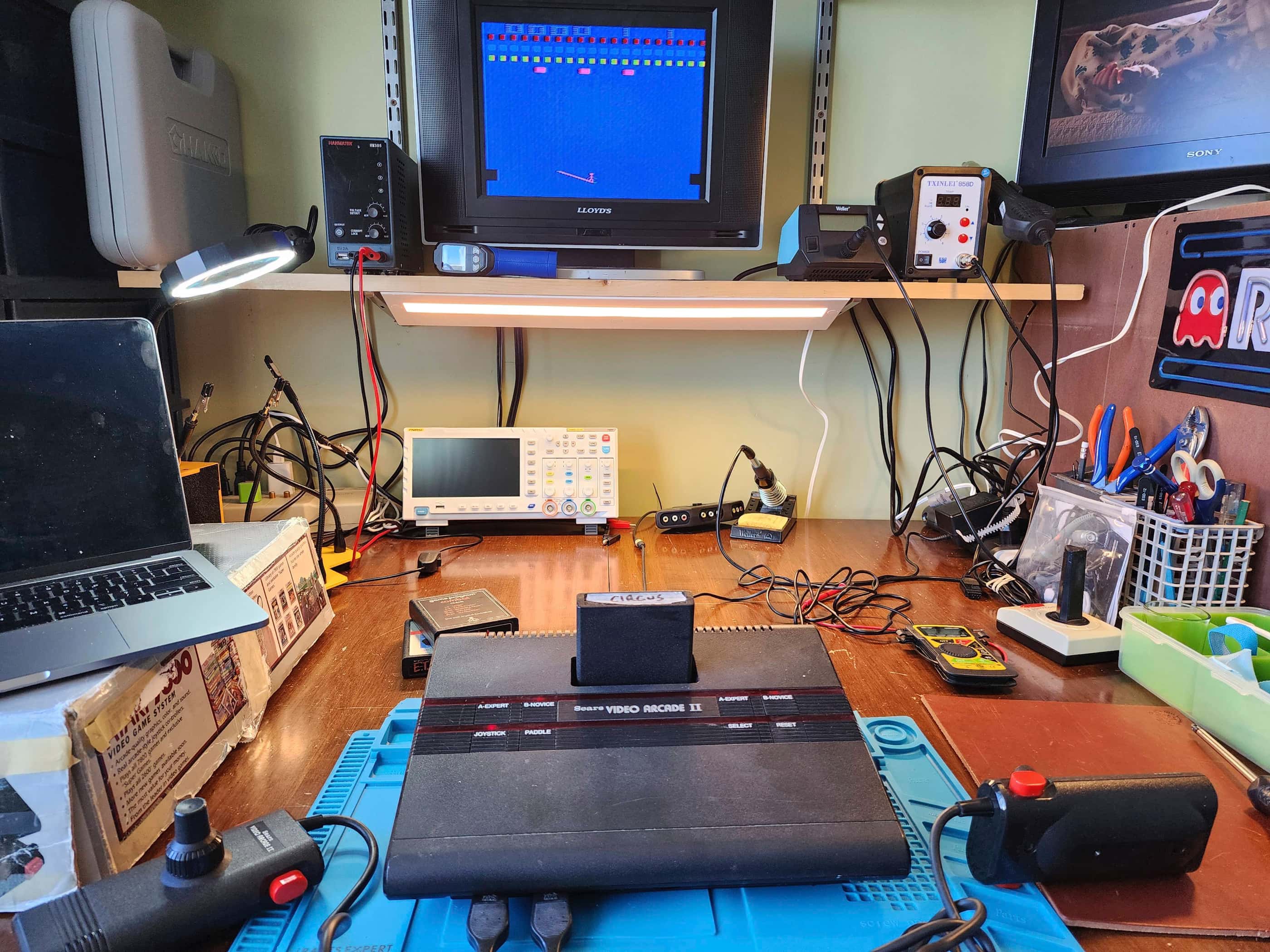
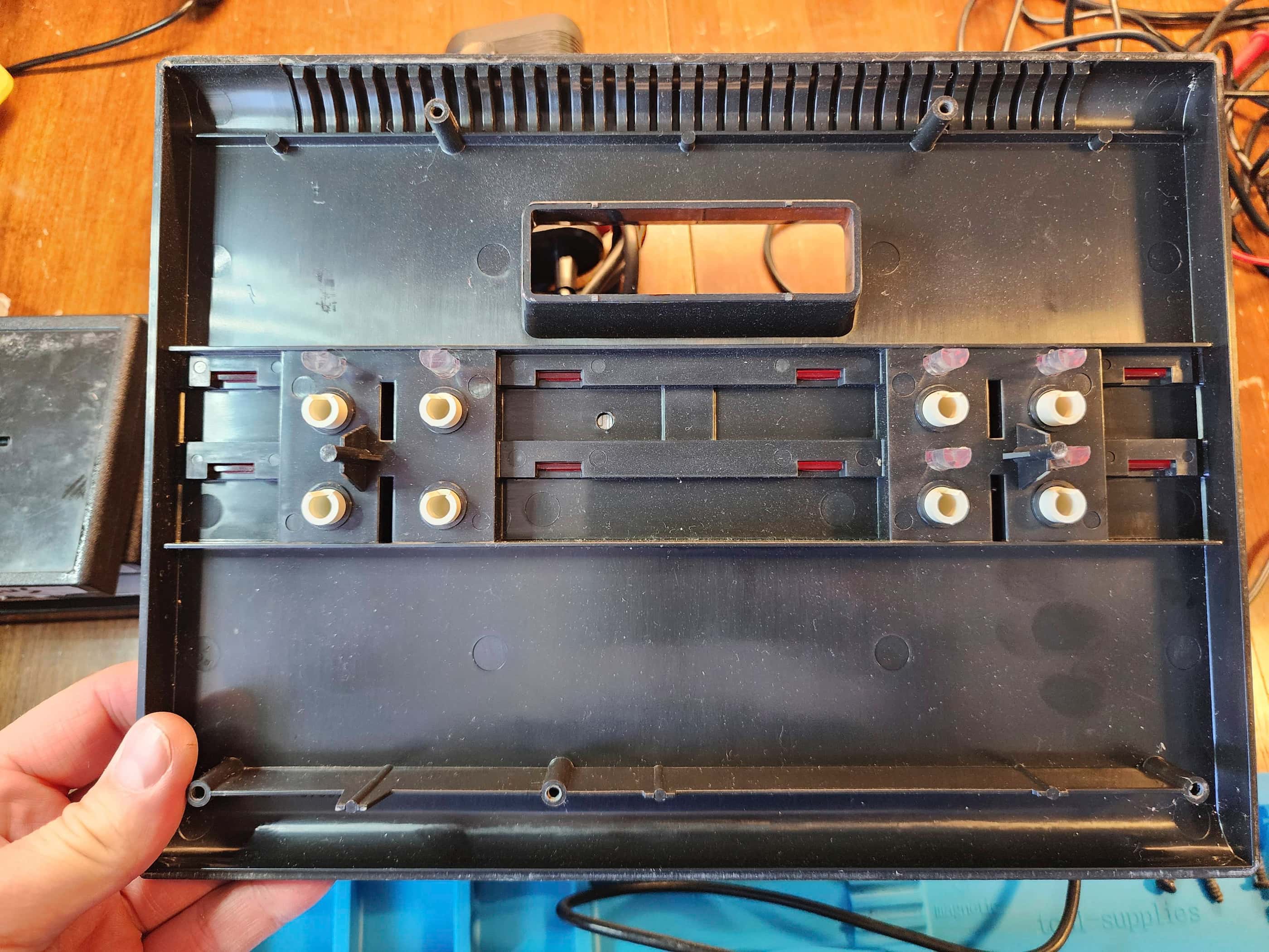
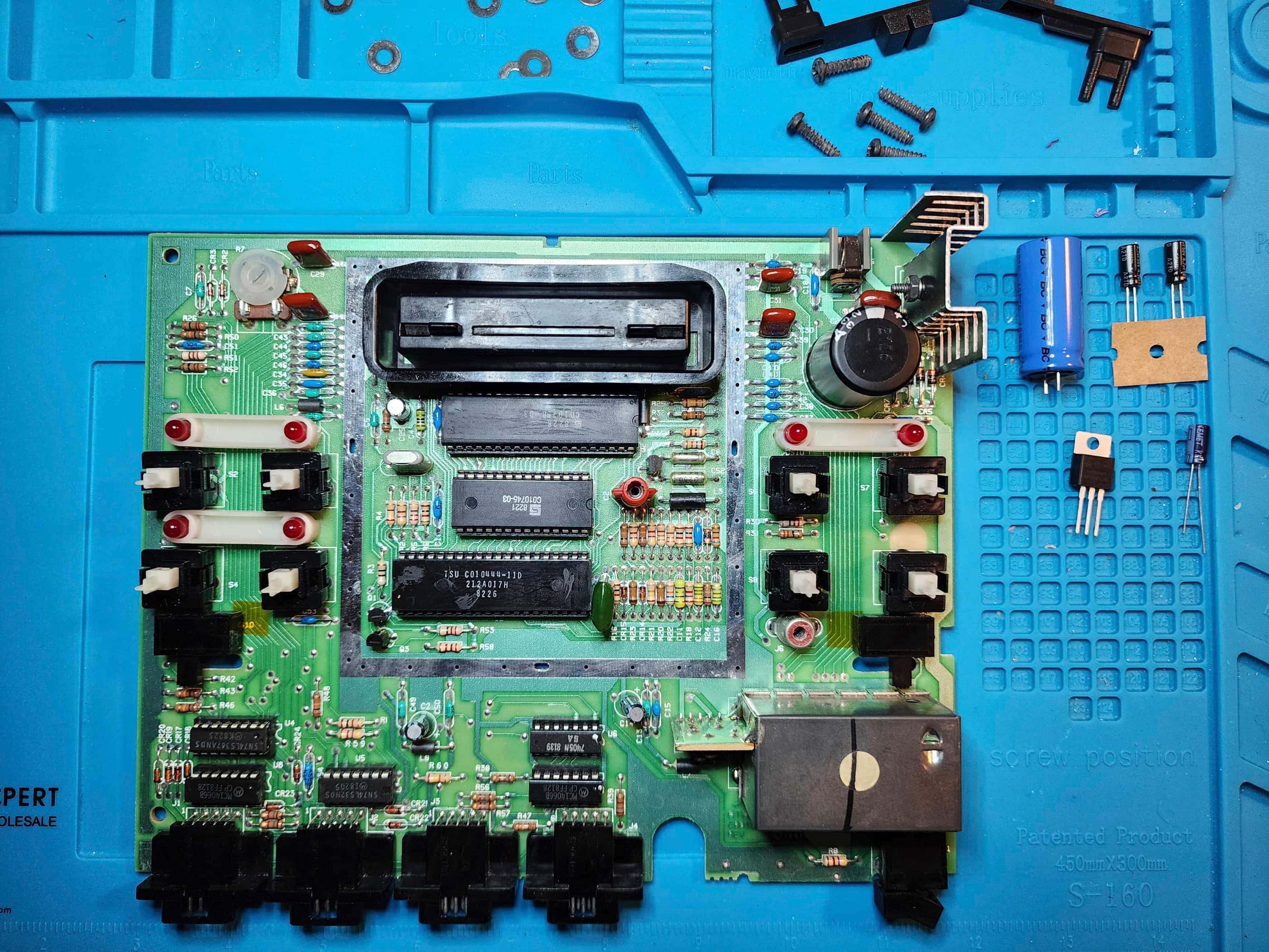
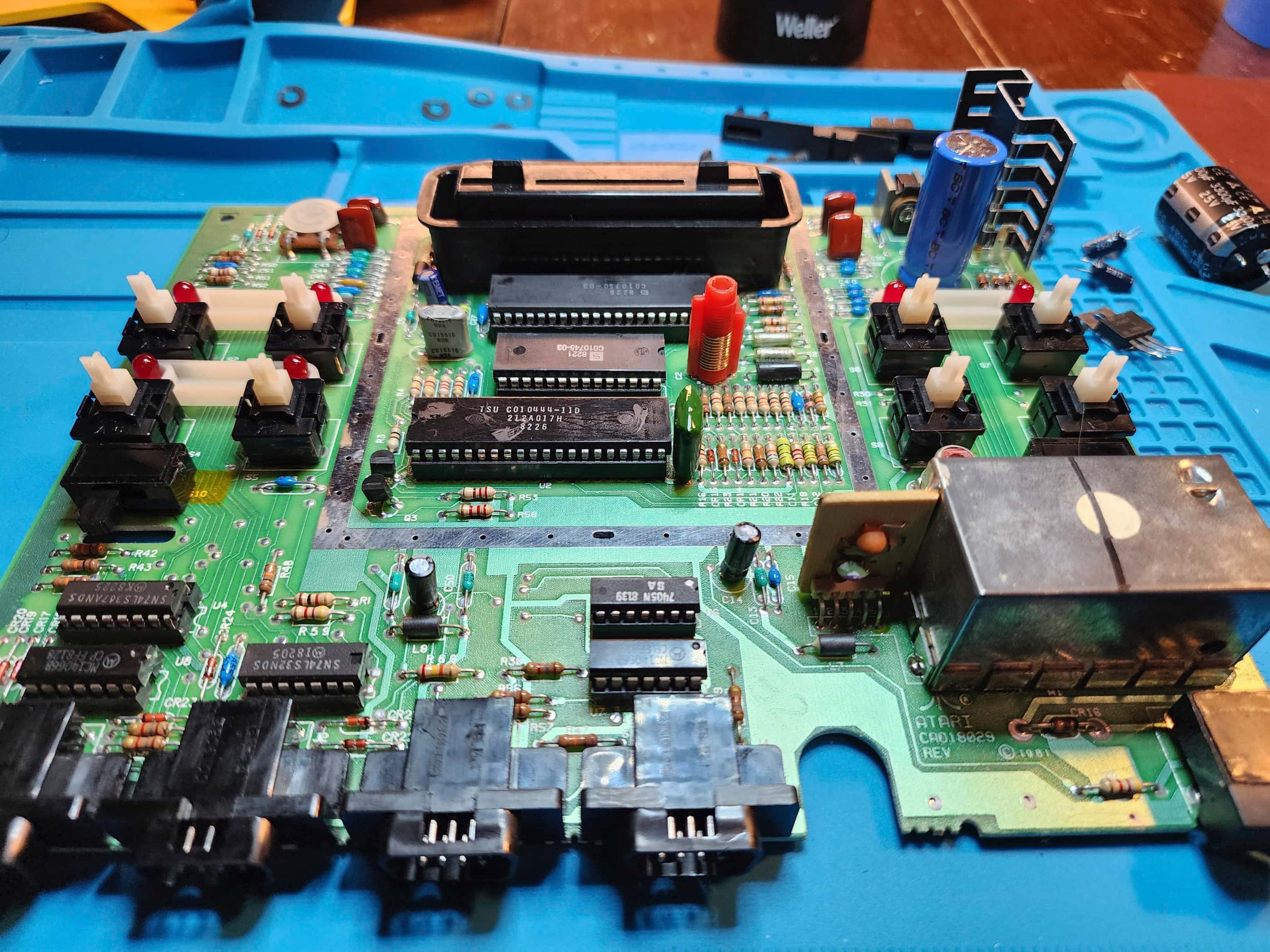
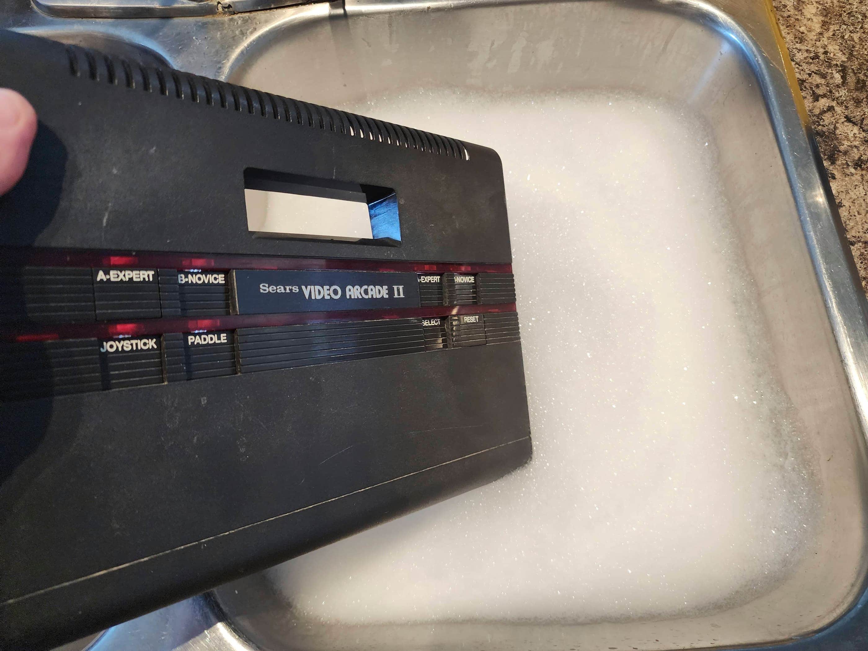
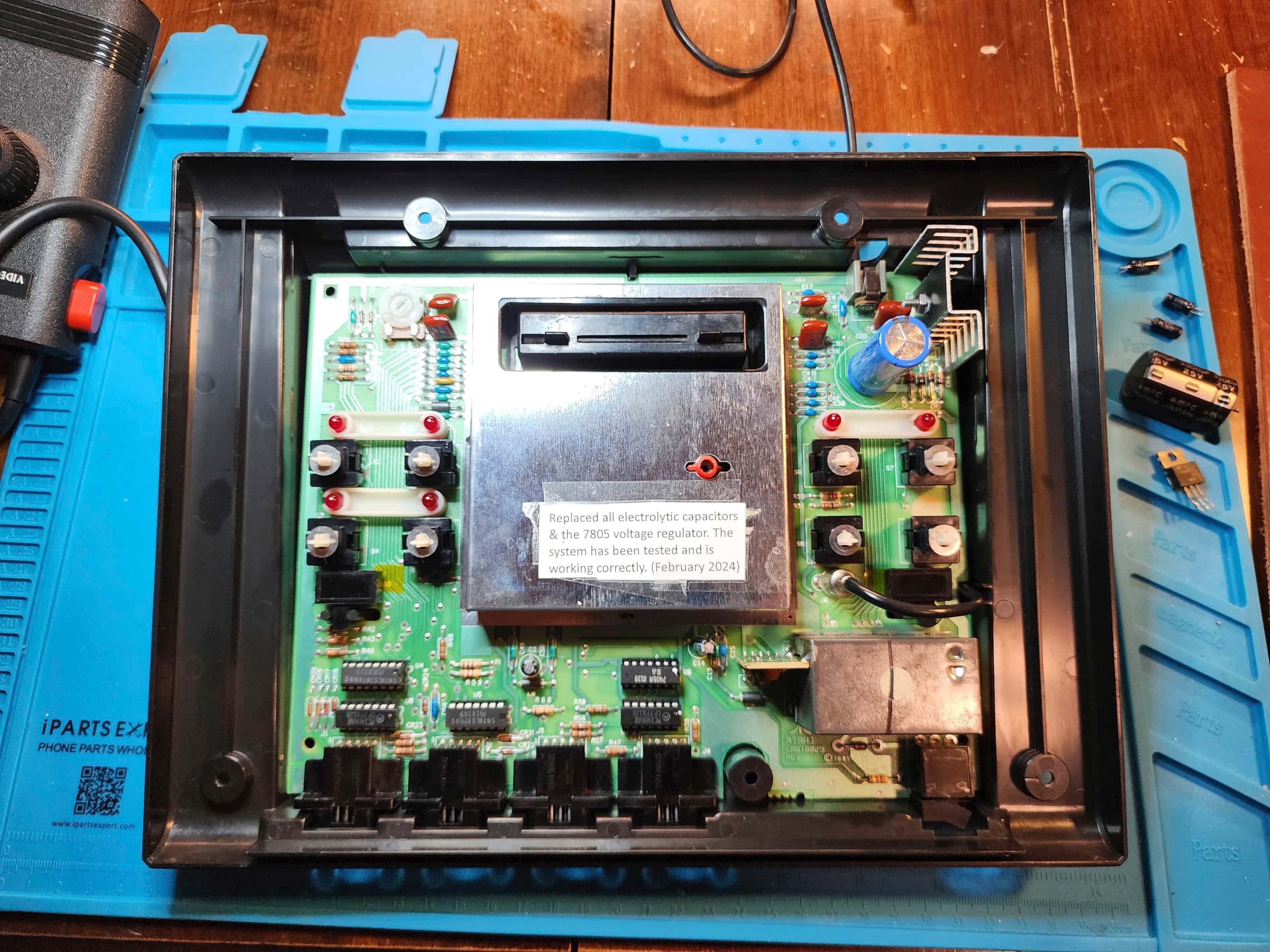
Though the console was dirty, the system fired up without a hitch. Moreover, the controllers both worked perfectly. I then proceeded to open everything up for an inspection and cleaning. Though it’s a redesigned 2600, the VAII / 2800 still has some major differences under the hood with the four joystick ports and the AC power supply being the most obvious. Other differences include a repositioned power switch along with new switches to toggle between joystick mode and paddle model.
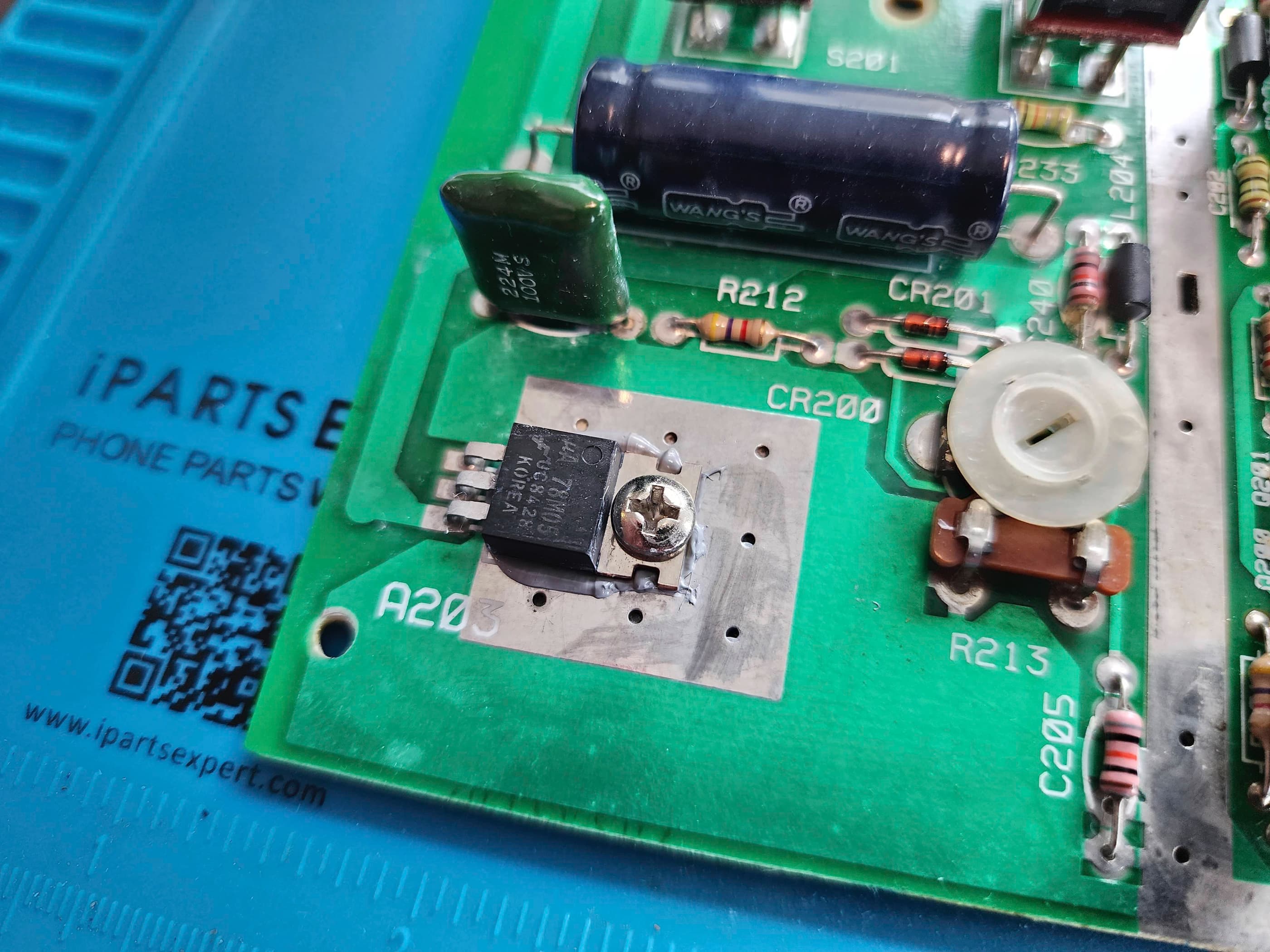
Even though the system didn’t need it, I did take the precautionary measure of replacing all four electrolytic capacitors along with the 7805 voltage regulator. After a thorough cleaning of the board and the cartridge slot, I ran it through some tests (including all the buttons and joystick ports) and everything worked perfectly. I then washed and polished the case and put everything back together.
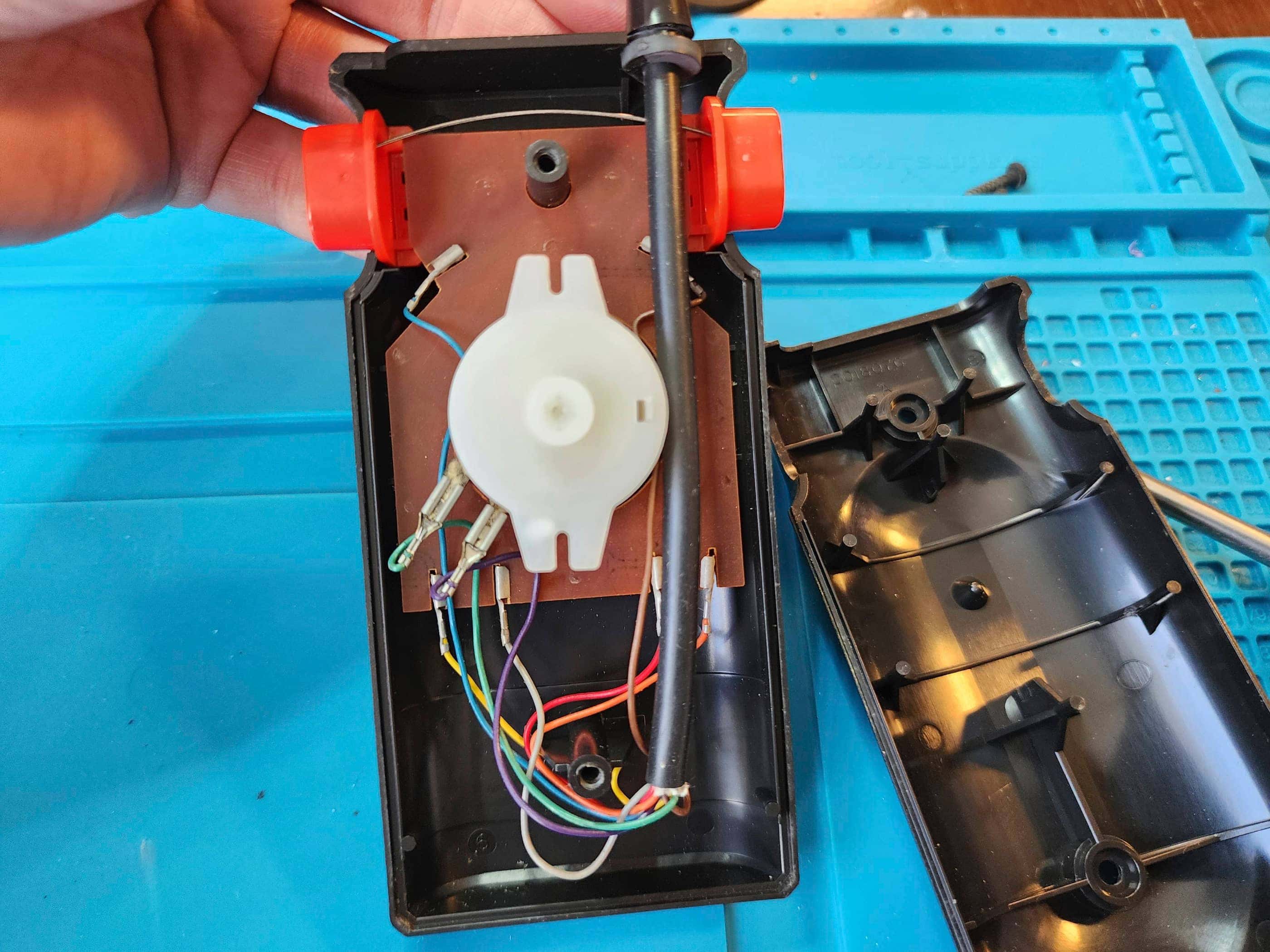
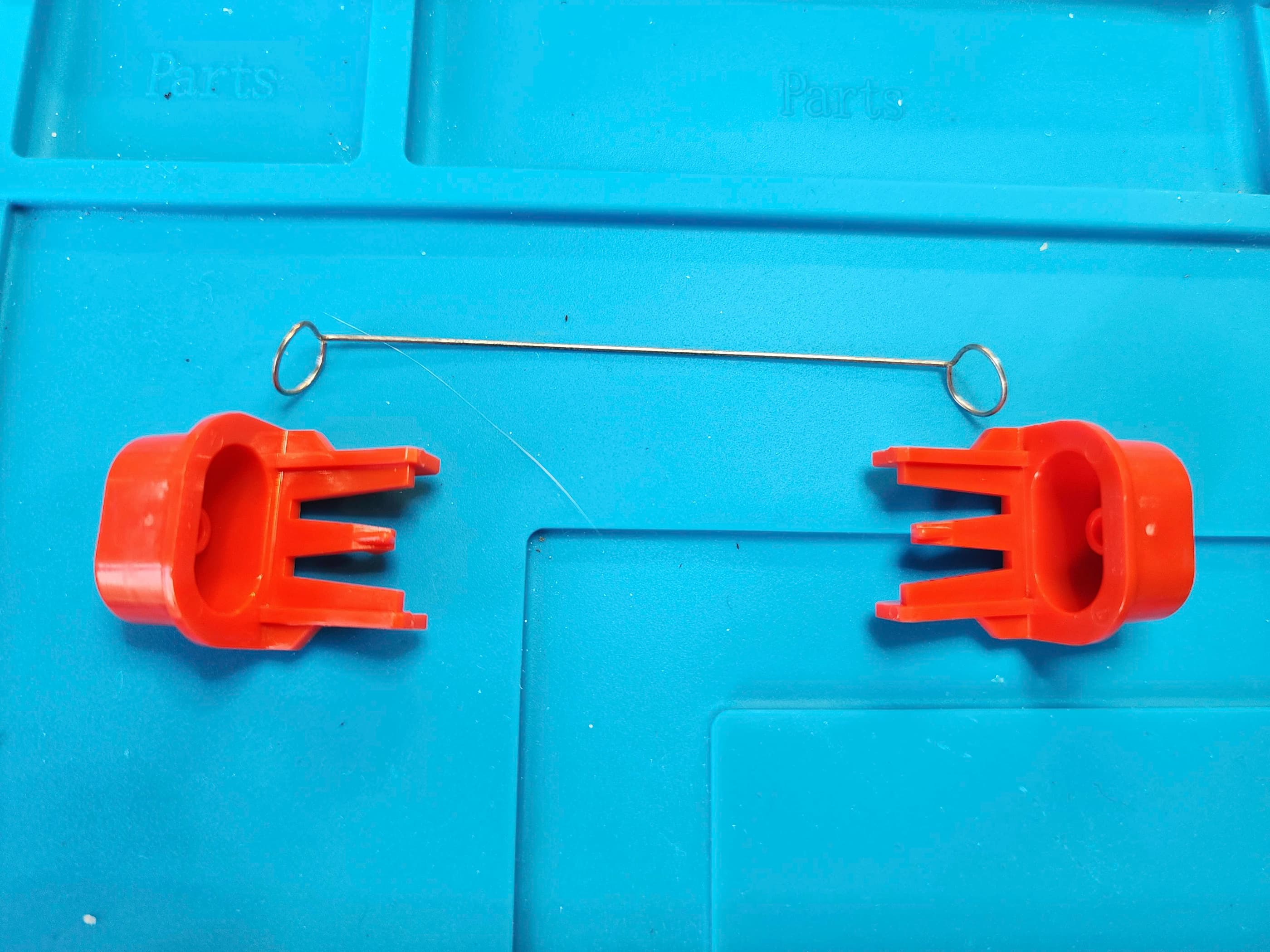
Next, I turned my attention to the controllers. As I’d never seen these controllers before, I was curious what was inside. Surprisingly, they were relatively clean and it didn’t take me long to clean the contacts, boards, and cases. I did not however, disassemble and clean the potentiometers for the paddles. As everything worked perfectly, I let sleeping dogs lie and reassembled both controllers.
I definitely lucked out with this system considering how cheap it was. In fact, the controllers cost more than the console – and I say, I lucked out with those as well. I now have a relatively rare and rejuvenated VAII / 2800 that works like new.
Parts & Products Used: 99% isopropyl alcohol; Chemical Guys Natural Shine; thermal paste; 7805 +5v regulator (1); electrolytic capacitors (radial) – 16v 10μF (1); 25v 3300μF (1); 50v 4.7μF (2)


You must be logged in to post a comment.