
Computers
8-Bit
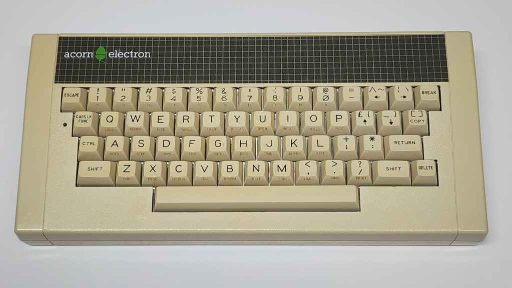
Acorn Electron
Years (1983-1985)
Interesting Fact: Originally in charge of Sir Clive Sinclair’s, Sinclair Research, Christopher Curry split from Sinclair in 1978 to form Cambridge Processor Unit (CPU) Ltd. in partnership with Hermann Hauser. (Source) Later that year, CPU rebranded as Acorn Computers and in 1980, launched the Acorn Atom as their first attempt to enter the home computing market. (Source) Based on the 6502 processor, the Atom was shipped as a build-at-home kit that sold 20,000 units. (Source)
Acorn’s breakthrough came in 1981 when it was awarded the British Broadcasting Corporation’s (BBC) Computer Literacy Project contract to produce an 8-bit computer that would be used within the UK school system. (Source) Designed for reliability the BBC Micro was produced between 1981 and 1994 and sole 1.5 million units. (Source)
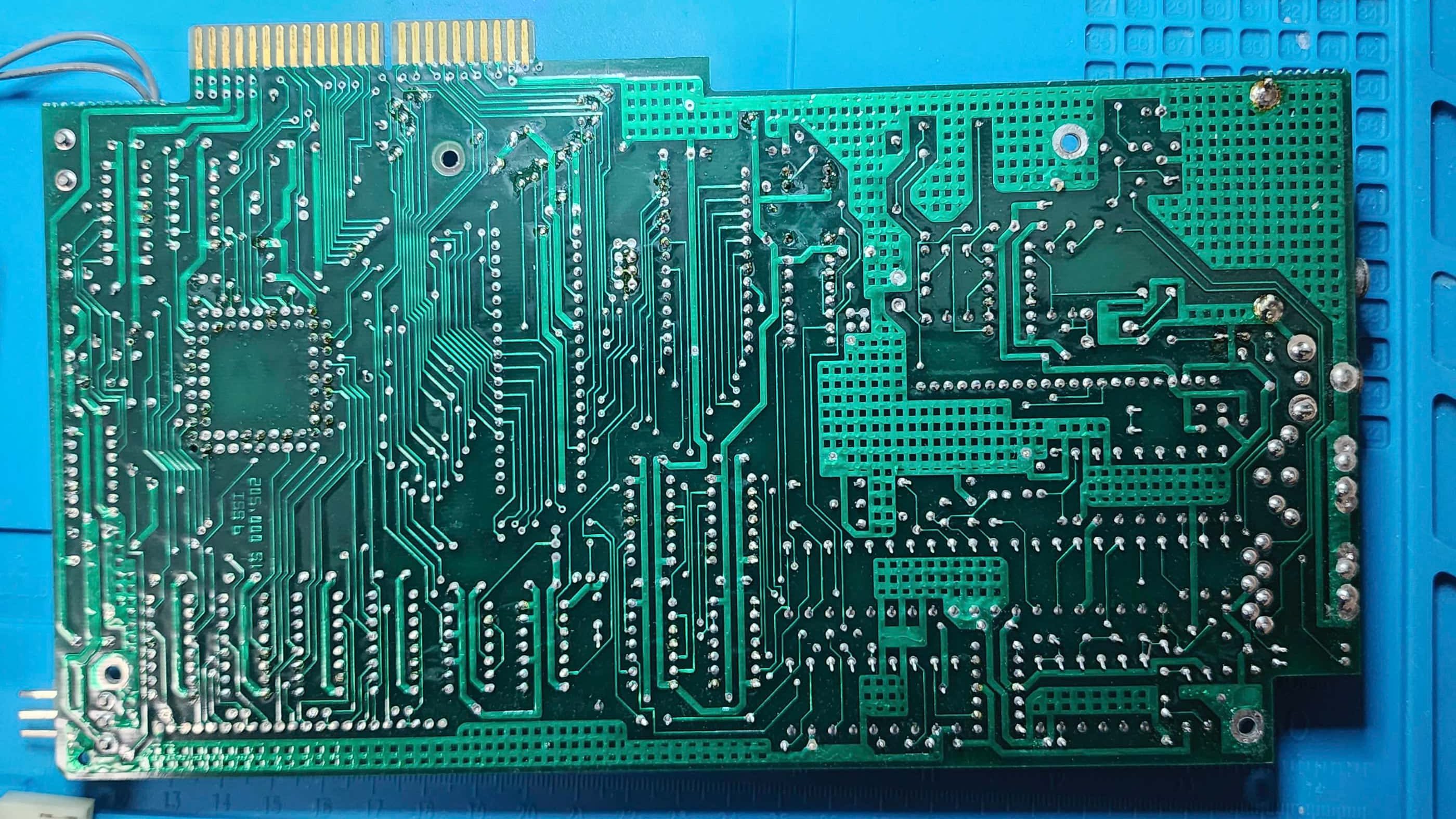
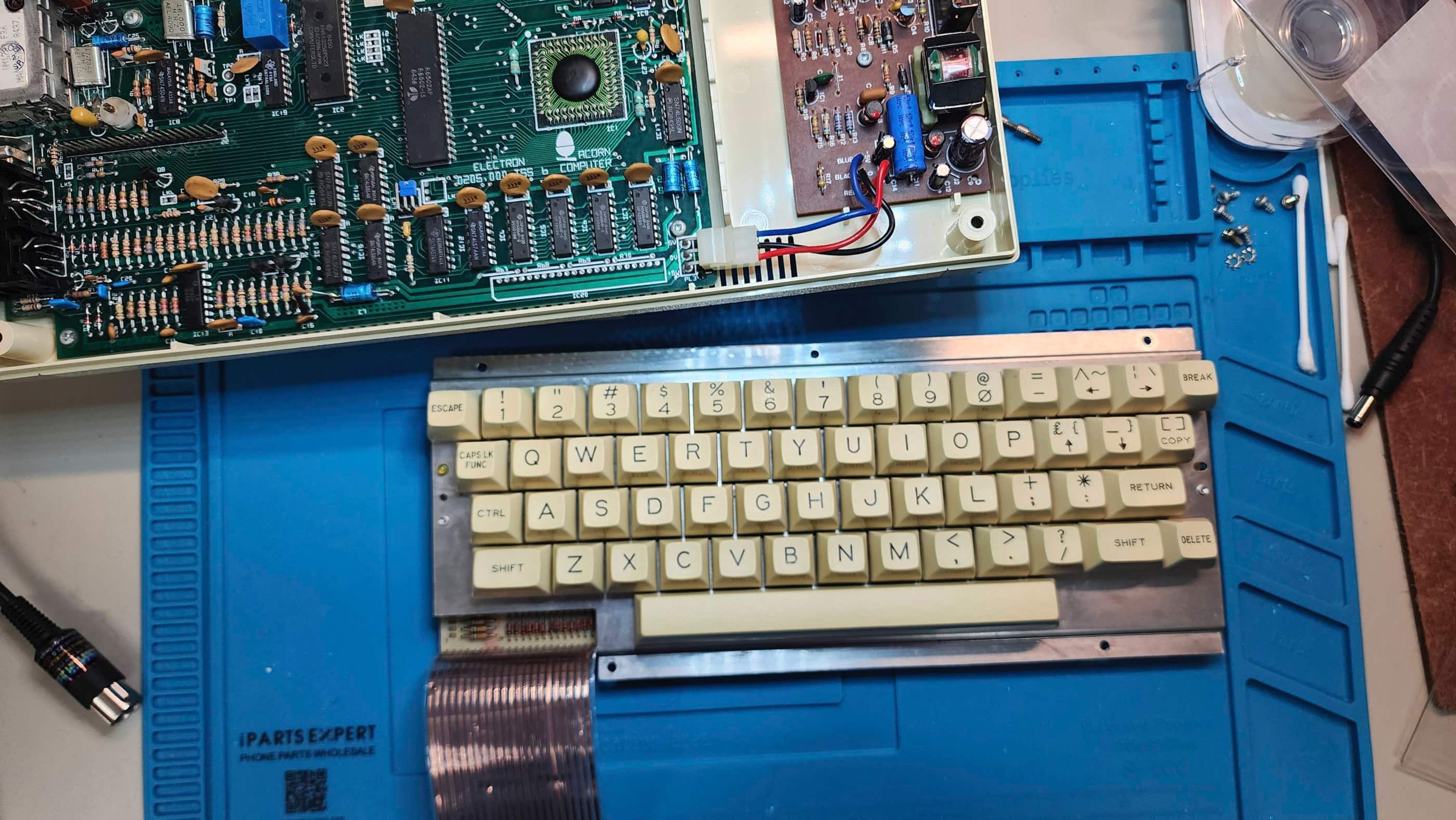
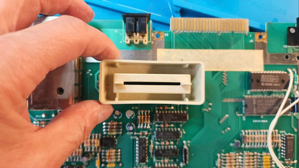
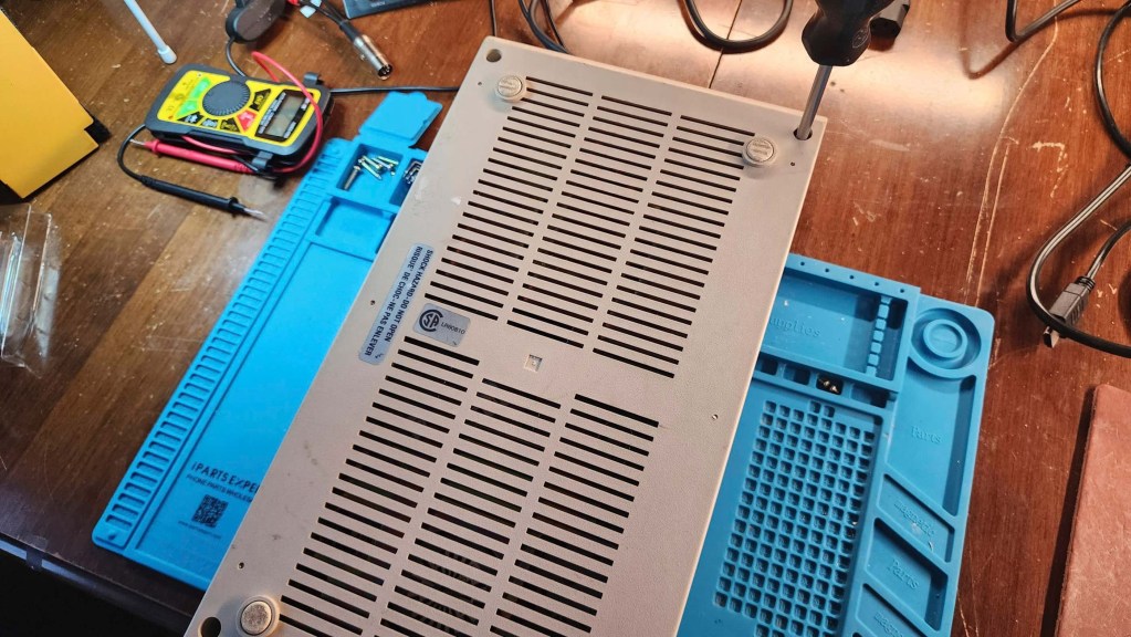
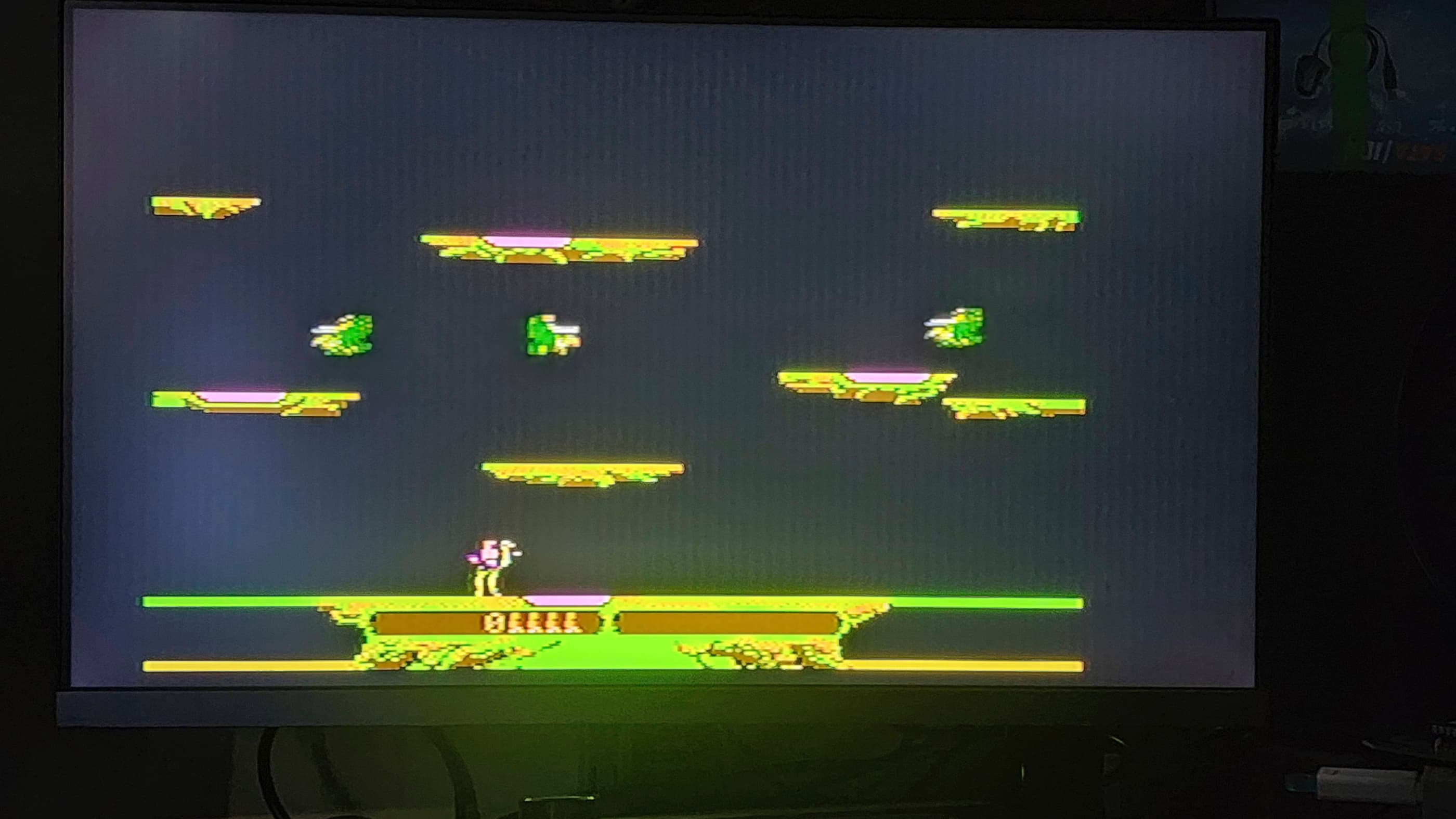
The Electron (or ‘Elk’) was Acorn’s attempt to bring an affordable BBC Micro Model B into the home market. (Source) Unfortunately, it ran into production issues as the company struggled to develop a new ULA (Uncommitted Logic Array) chip that would reduce the number of chips used by the Model B down to around a dozen for the Electron. (Source) The delay caused Acorn to miss the 1983 Christmas shopping window and though computing reviews were favourable, early models had a reported 25% failure rate. (Source) In total, between 200,000 and 250,000 Electrons were sold between 1983 and 1985.
Condition When Acquired: Paritally Functional
Current Condition: Fully Functional

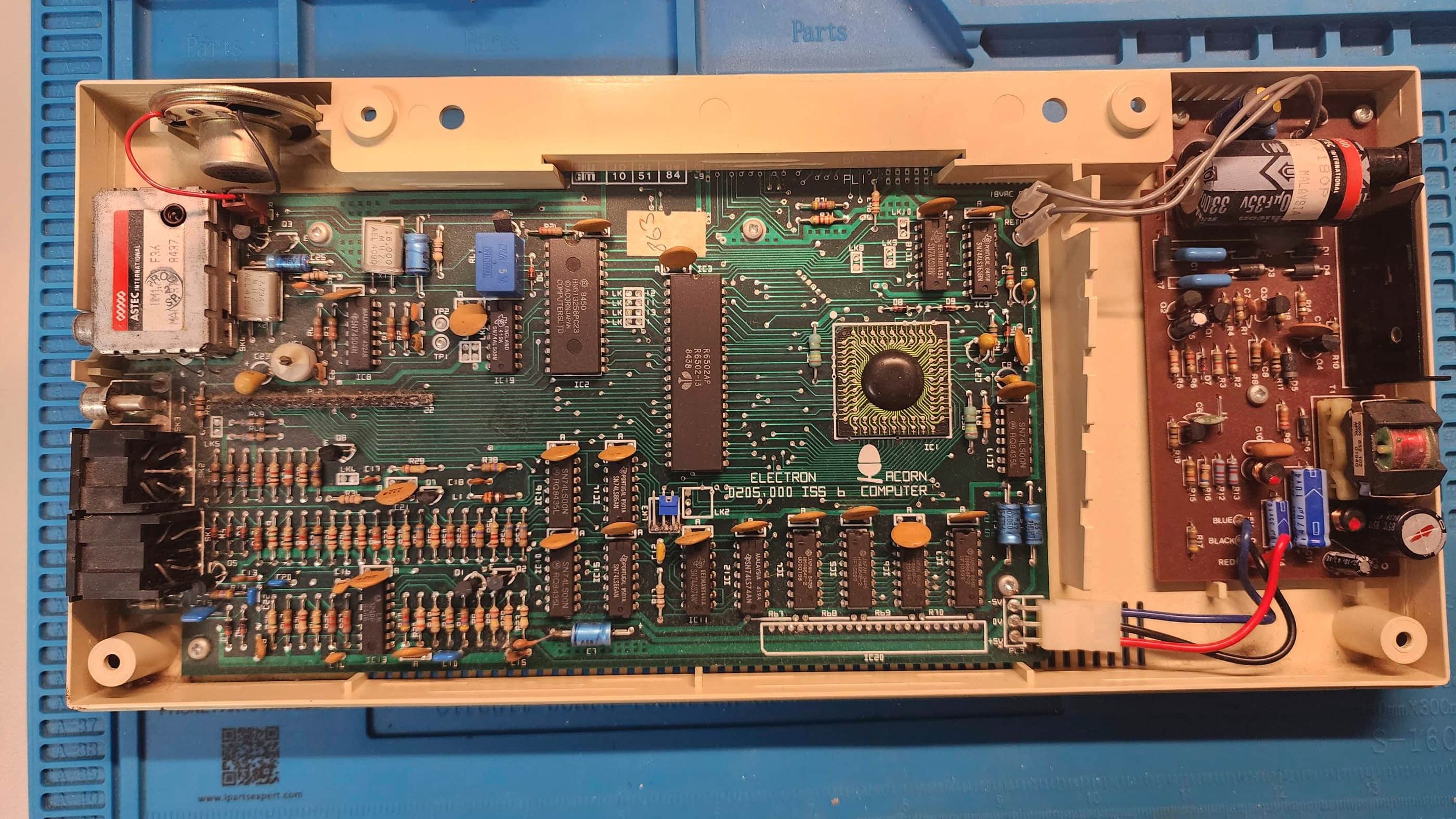


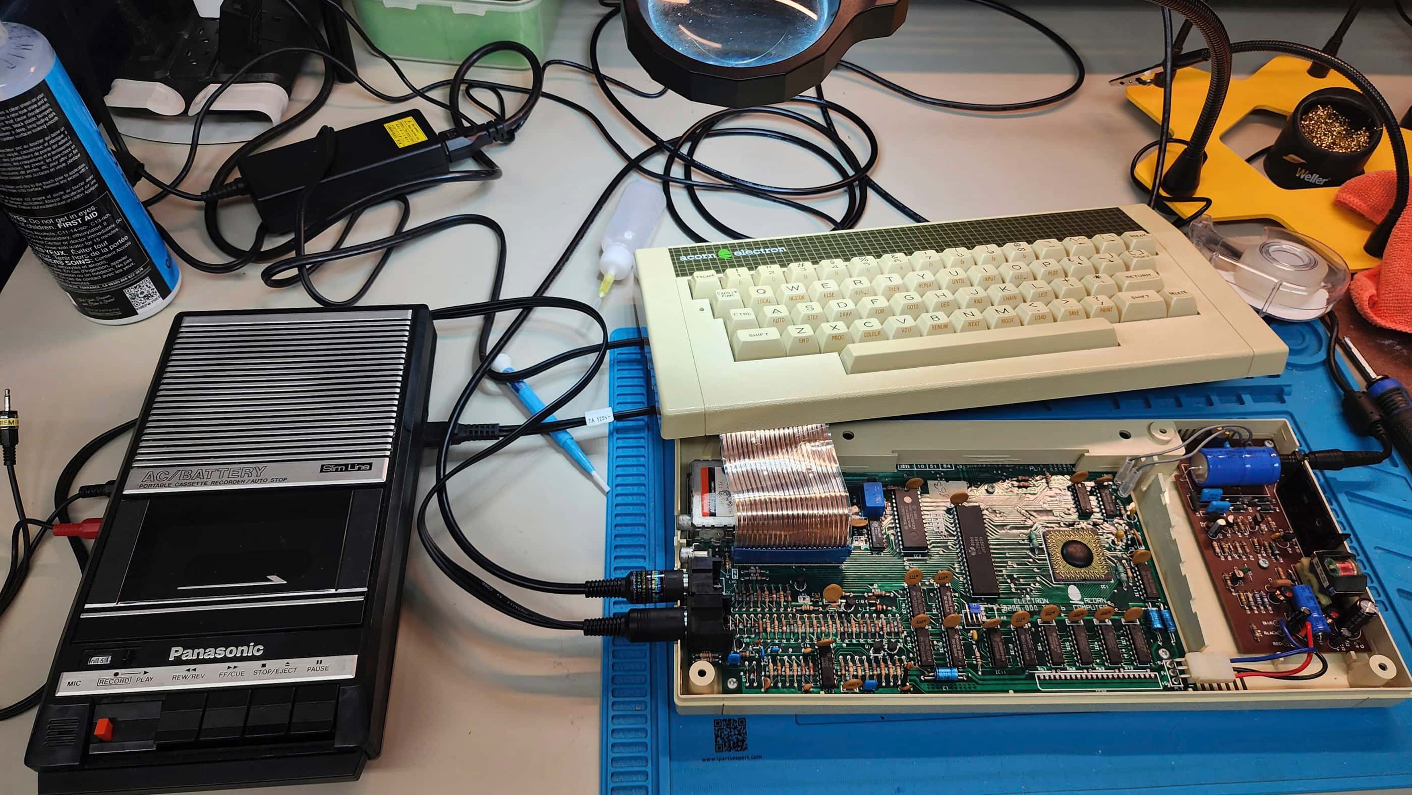


Project Details: As with my Amstrad CPC464, I’d never tried an Electron (‘Elk’) before, so the entire process was a huge learning curve for me. On a bit of a whim, I’d put in a bid on eBay UK for this ‘Elk’. It was advertised as untested (isn’t everything on eBay 🤔) and it only had a couple of photos accompanying it. The seller said it had been found in an attic but since they lacked the power cable or any other cables, they had no idea if it would even turn on.
Surprisingly, this item must have been overlooked by other bidders, because I won the auction without having to bid much at all. In fact, I think the shipping cost ended up being the most expensive part of acquisition. Still, even with shipping, it was a good deal and if it actually worked, it would turn into a super amazing deal.
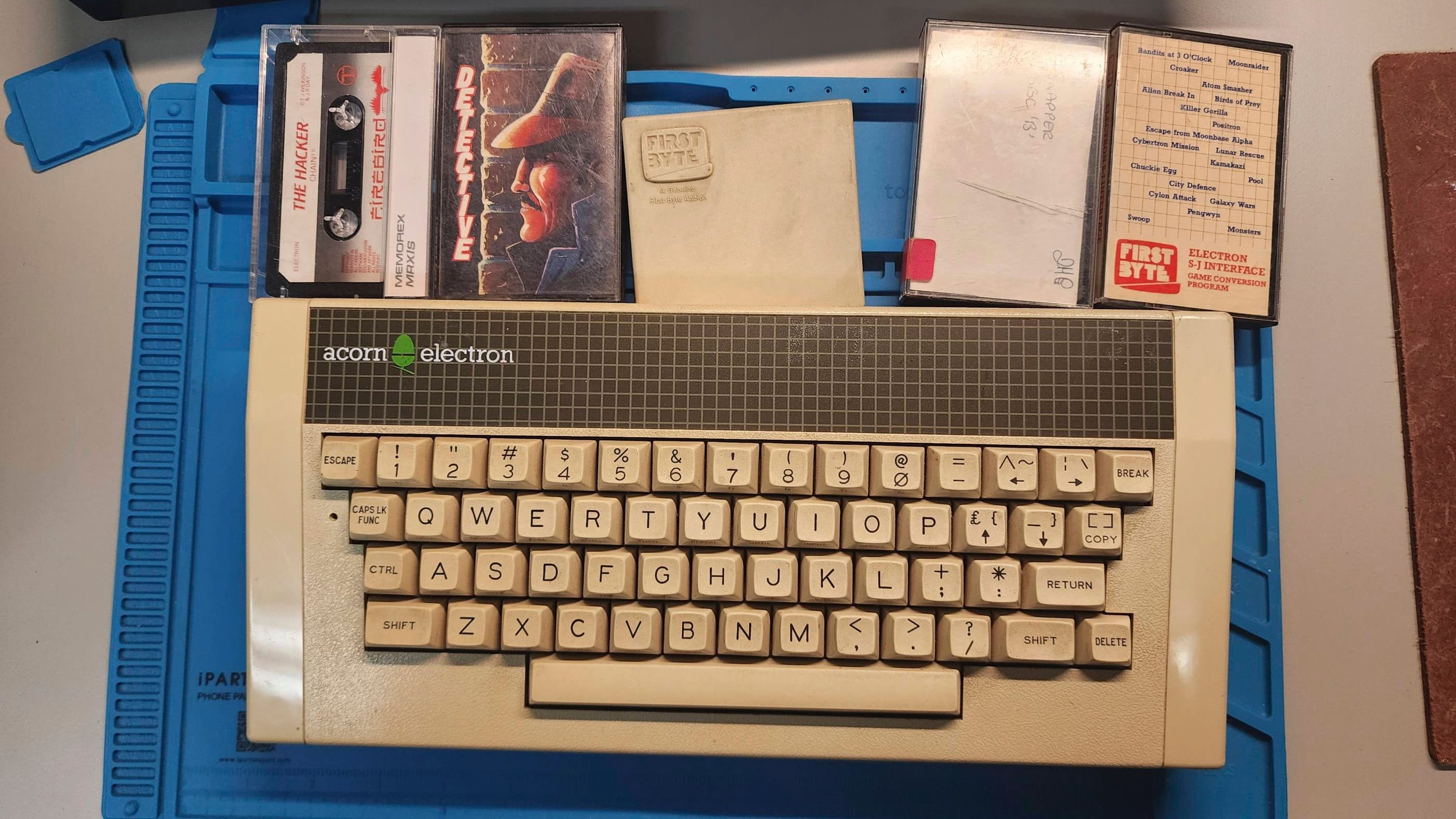
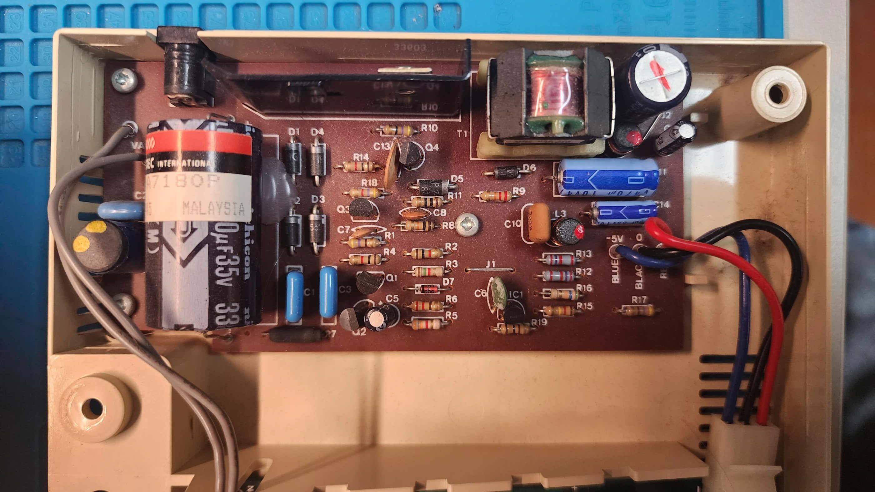
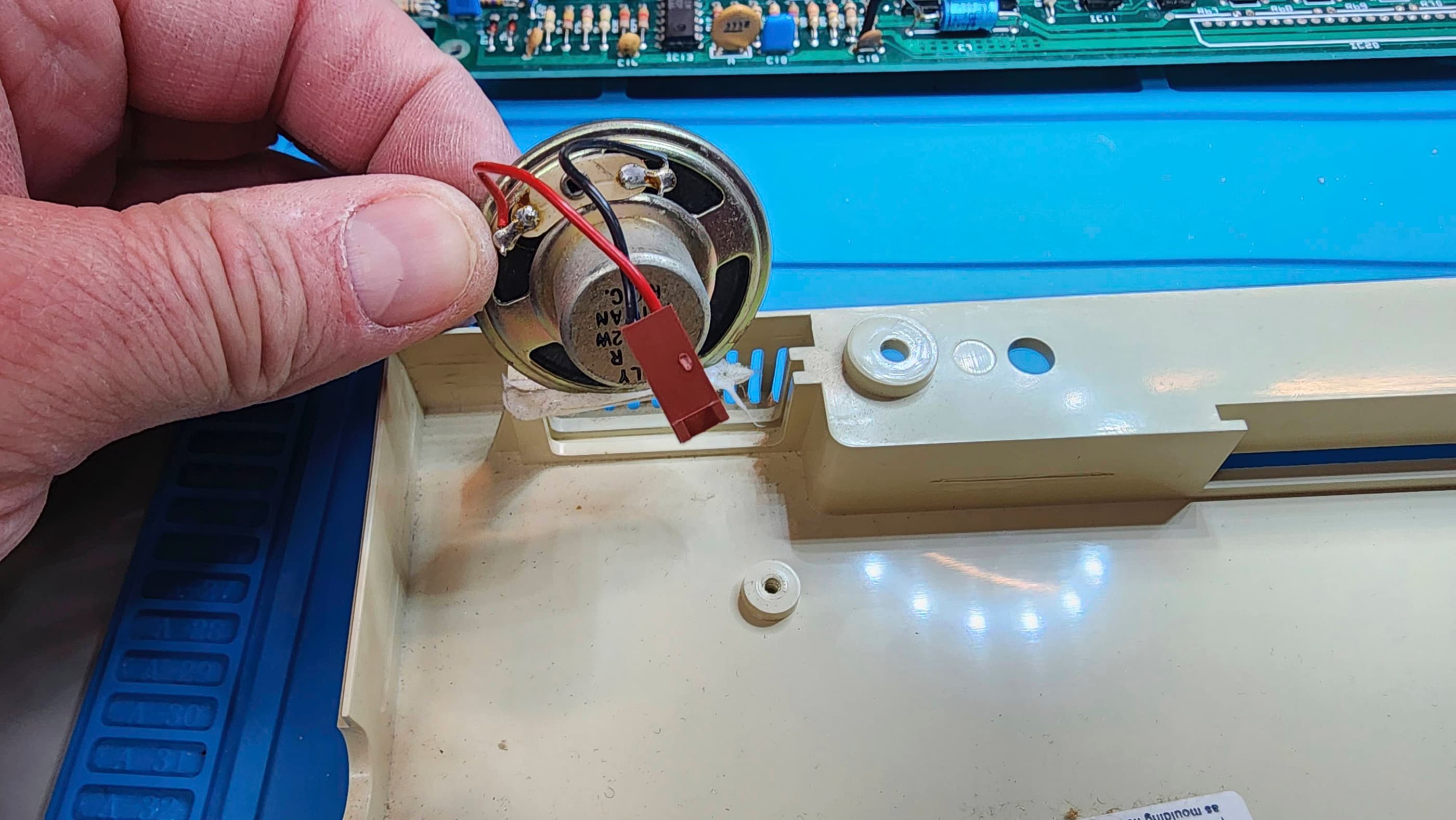
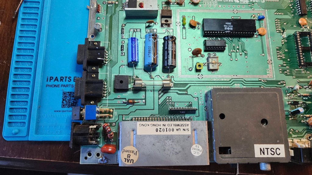
When it came, I was a bit nervous because the box was in rough shape. However, the seller had put enough packaging inside, and the ‘Elk’ survived. It also came with four cassettes and a joystick interface device. As it did not come with the original 19 VAC PSU, I ended up using a Toshiba laptop 19 VDC 3.95 A PSU (Model: PA3468E-1AC). Even though it was a DC PSU, much like I did for one of my Intellivision IIs, running a DC current through the power jack does not hurt the machine. The bridge rectifier that converts AC to DC has no problem taking in DC instead of AC. My real concern was making sure that the Toshiba PSU was centre positive and it was.
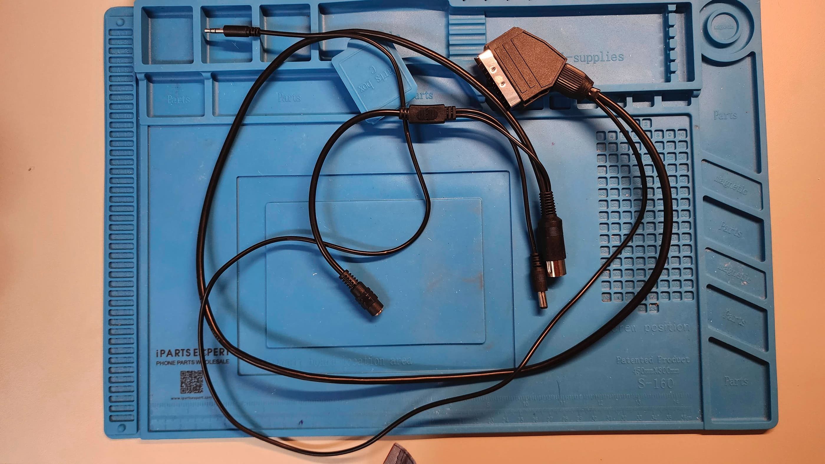
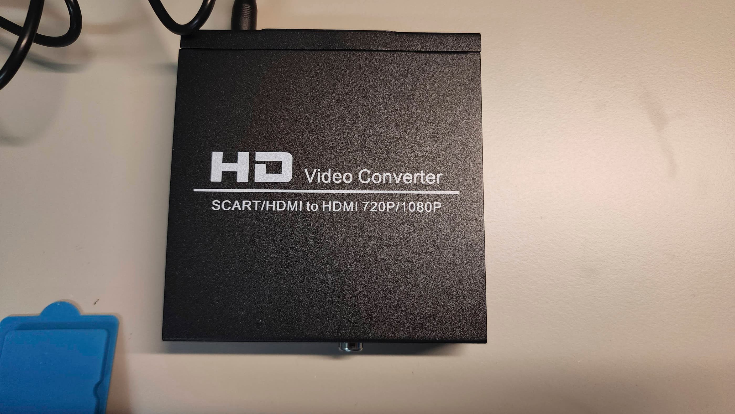
However, before I could power it on, I needed to locate an Acorn RGB cable and an Acorn cable for a cassette player. Fortunately, I found Retro Computer Shack in the UK to be excellent supplier for both the custom RGB cable and the custom cassette recorder cable. As the RGB cable was SCART, I could use the RGB SCART to HDMI converter that I had already purchased on Amazon for the CPC464.
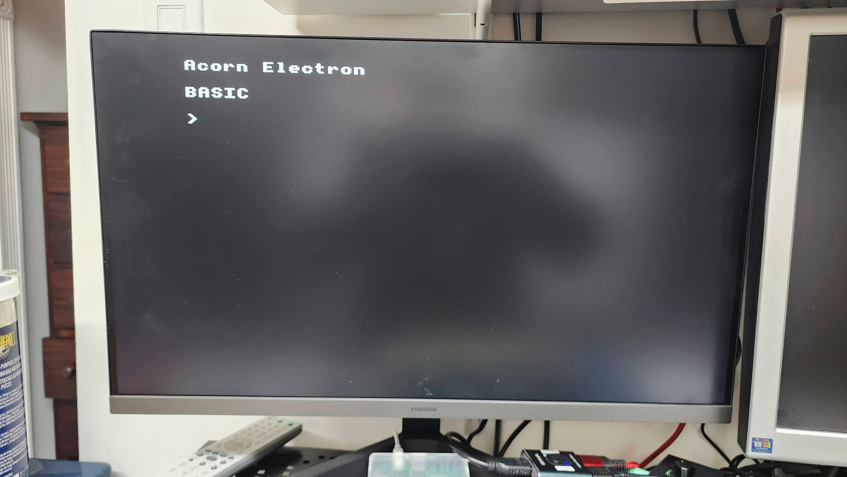
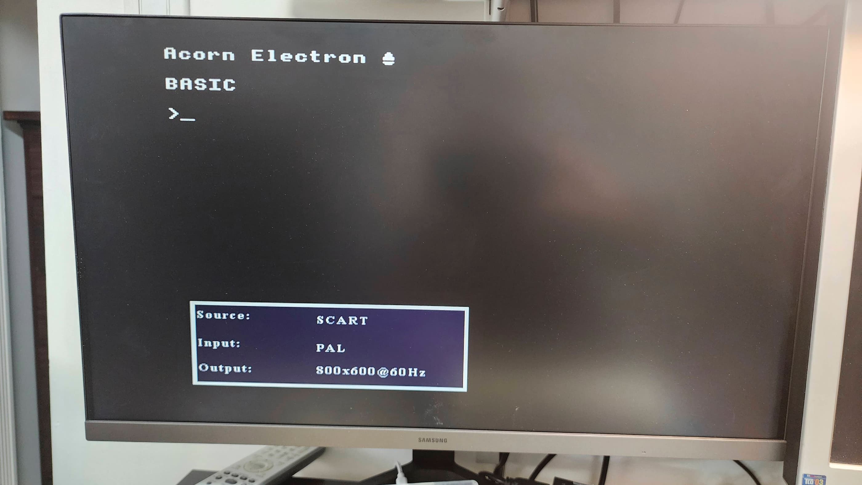
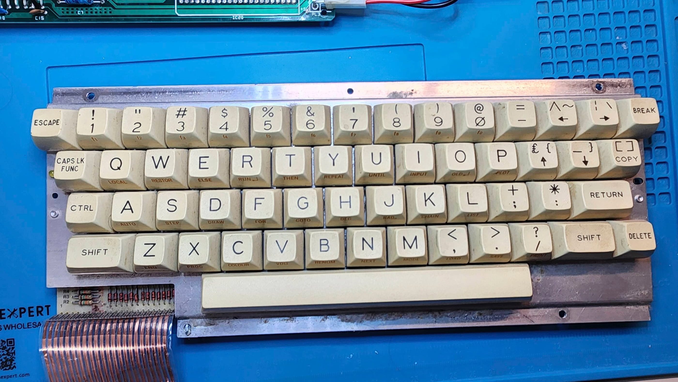
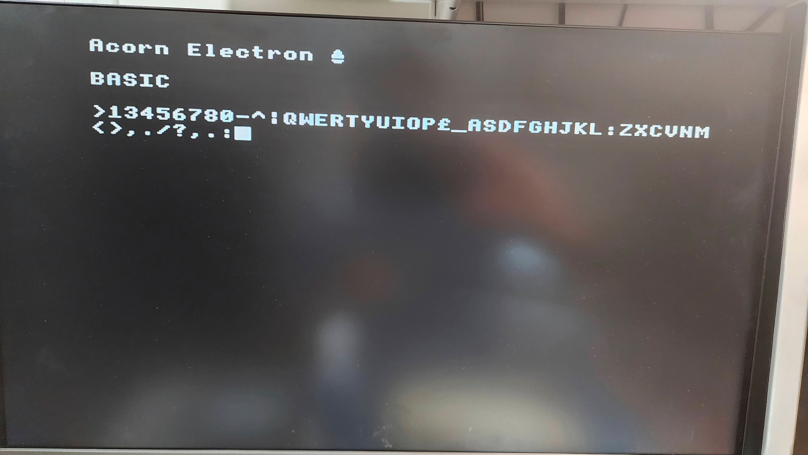
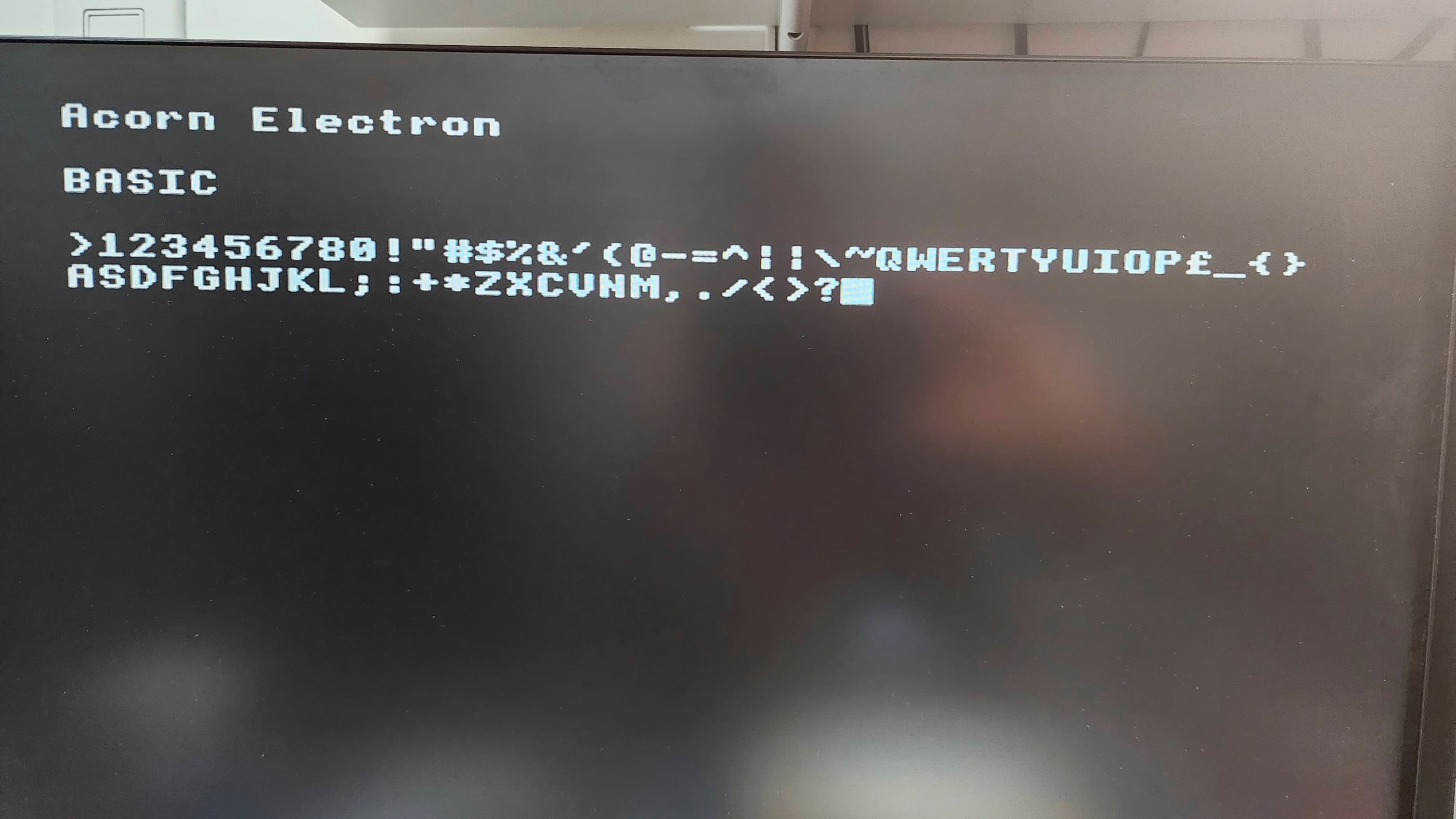
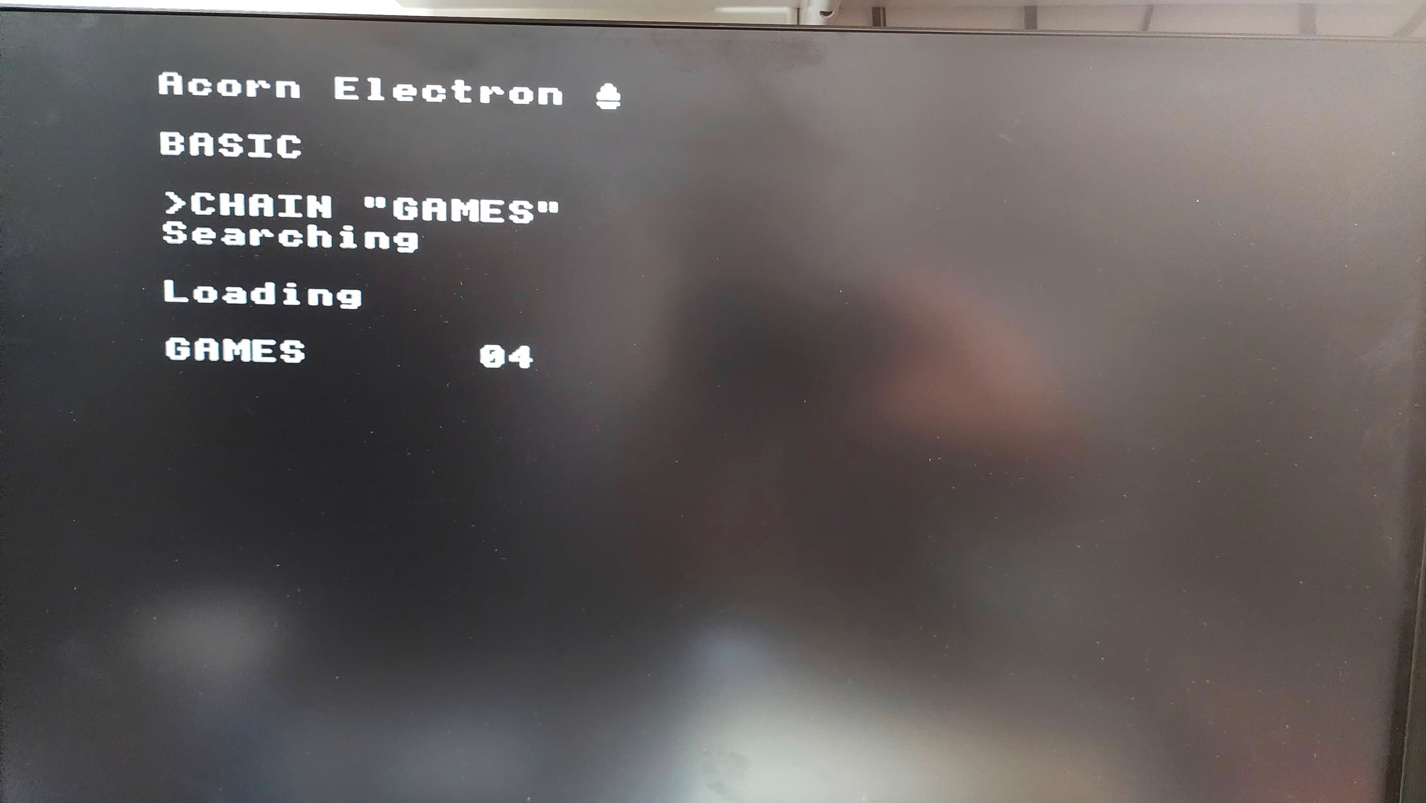
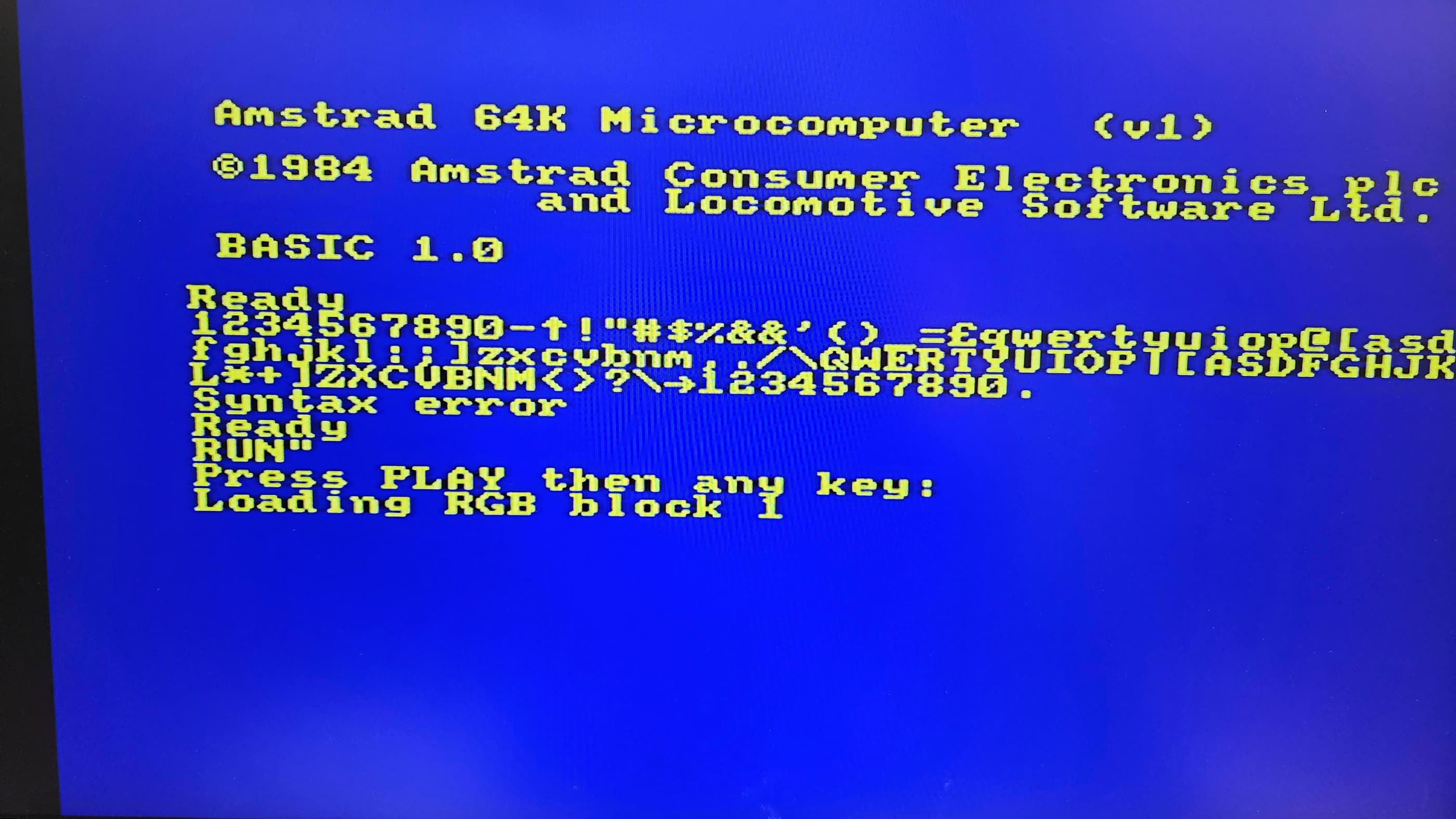
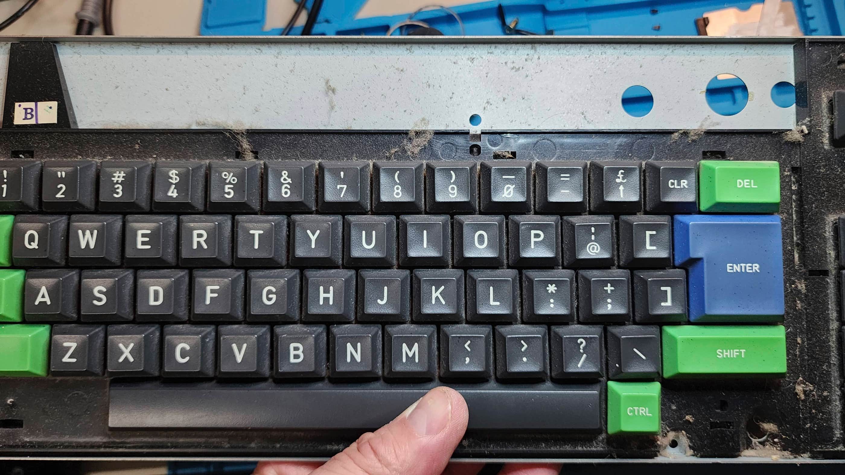
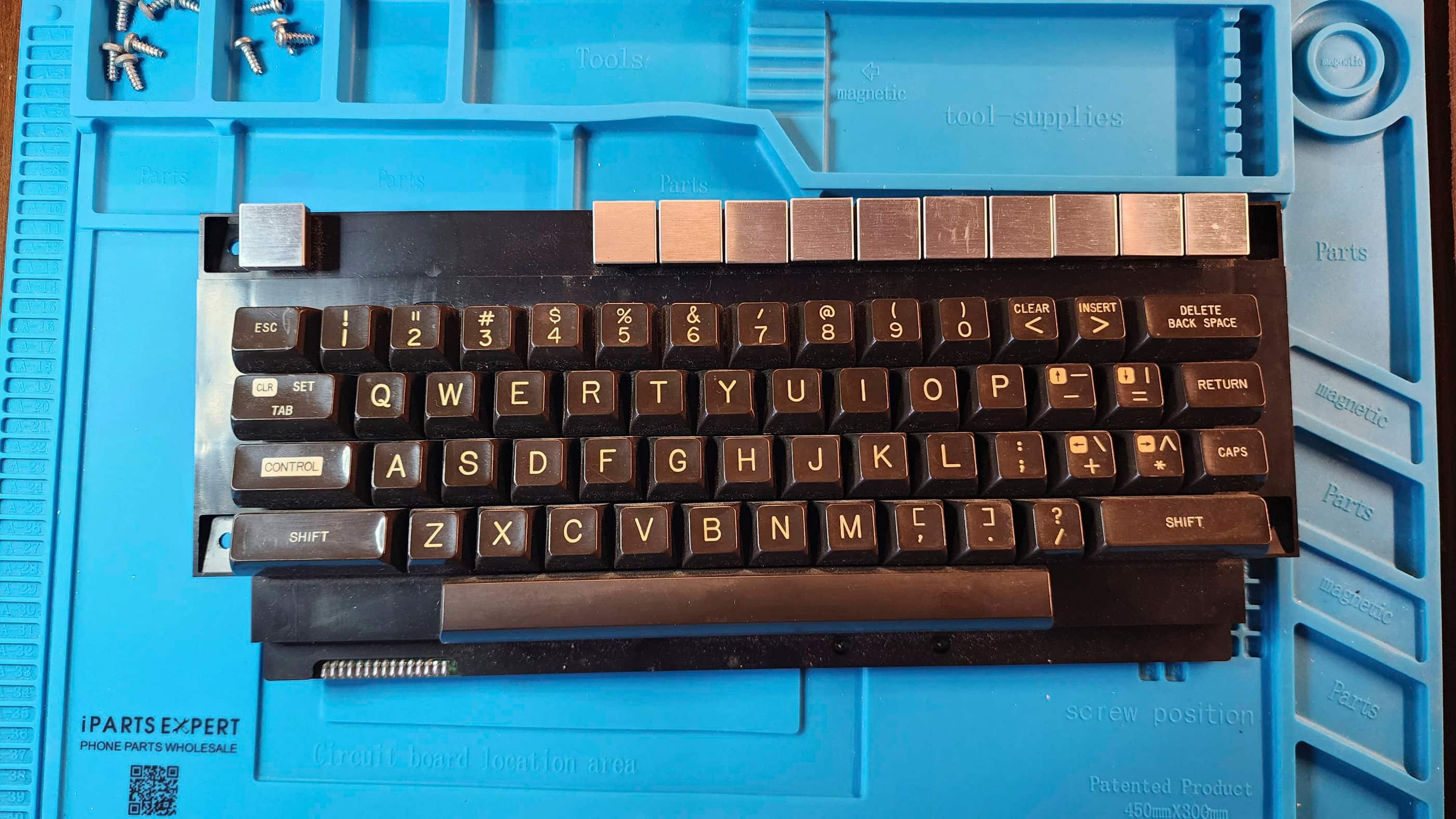
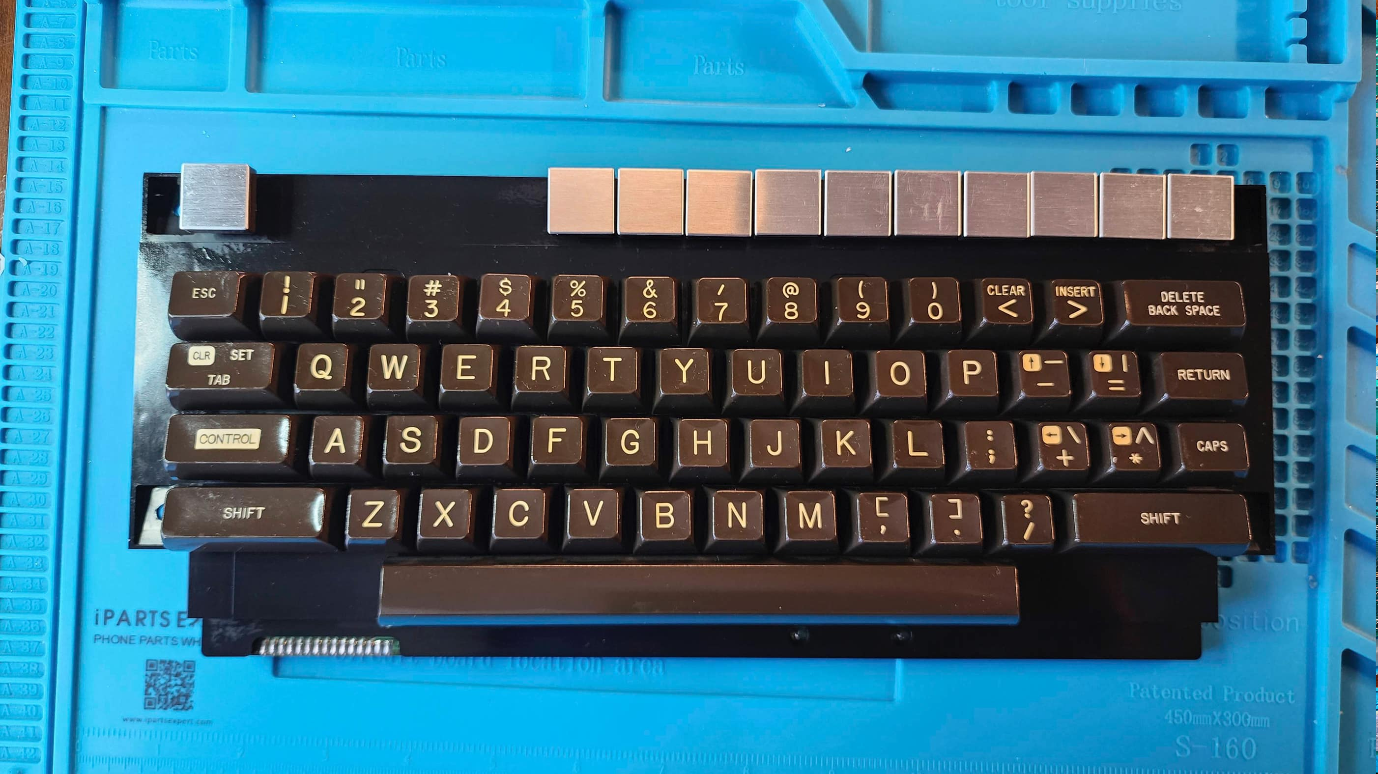
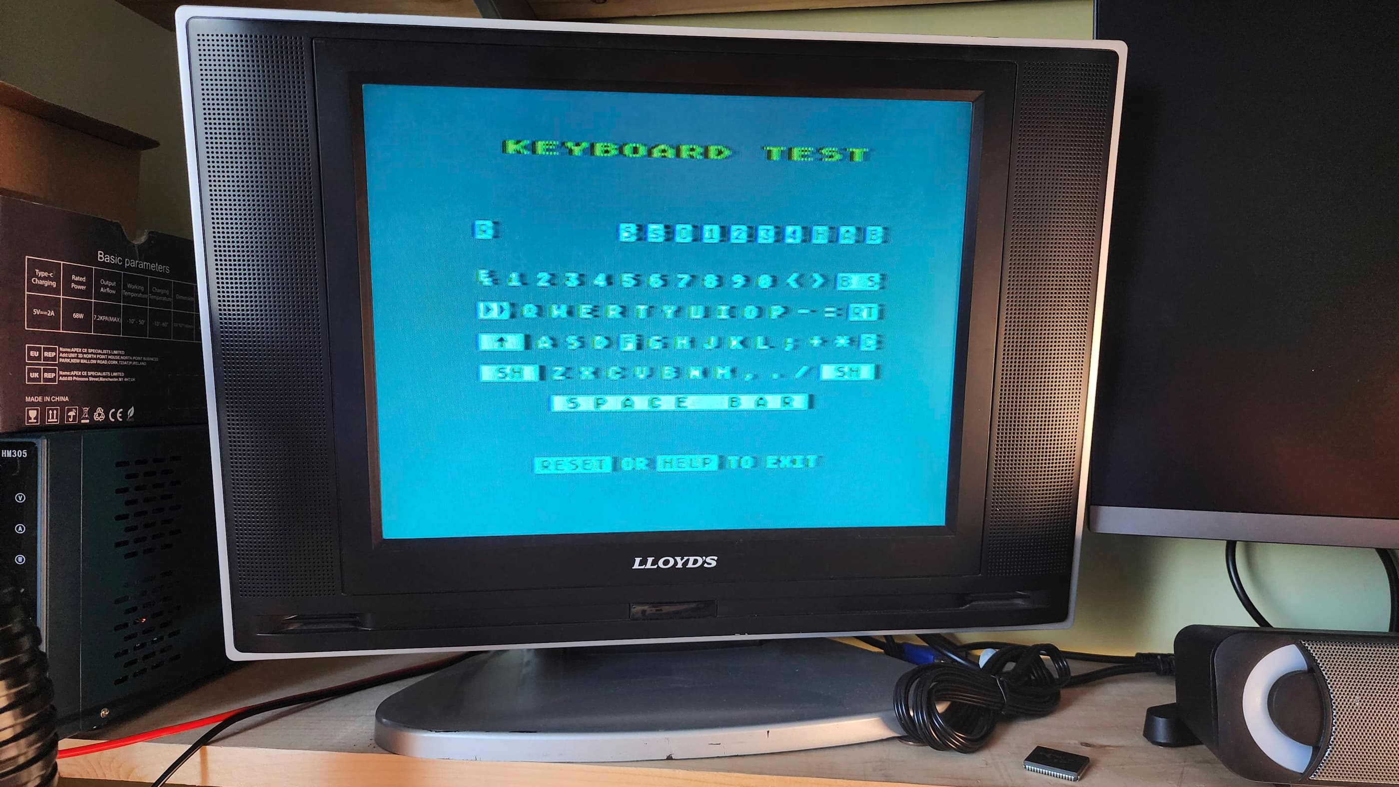
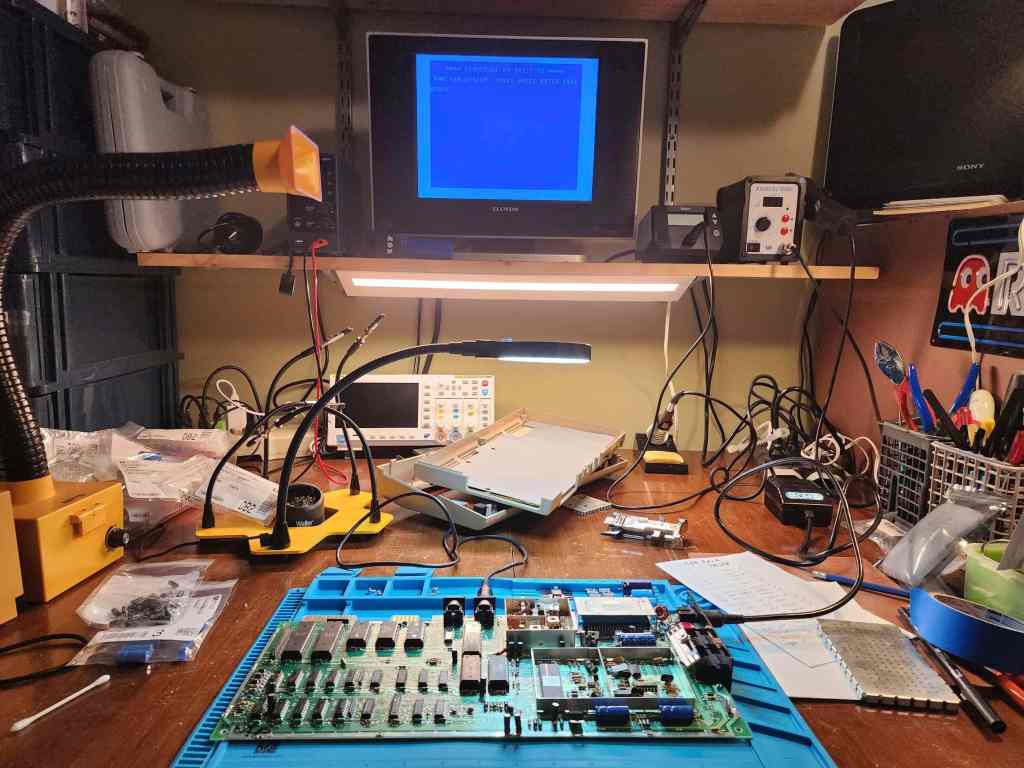
I was ecstatic when the ‘Elk’ turned on and displayed ‘Acorn BASIC’ with a nice, clear picture. However, a quick test of the keyboard revealed that a number of keys weren’t working and given how dirty the unit was, I was hoping that this would rectify itself with a good cleaning.
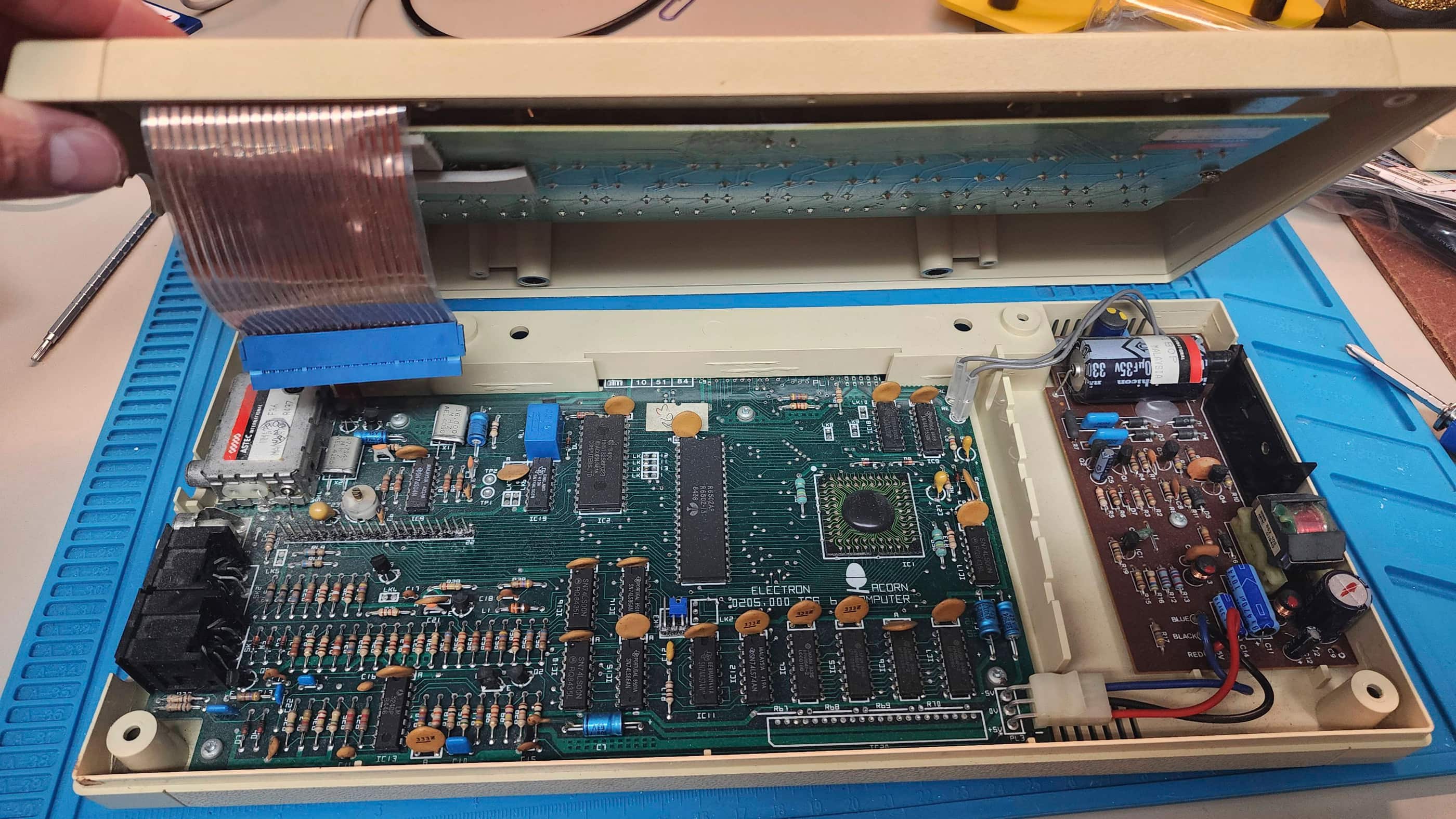
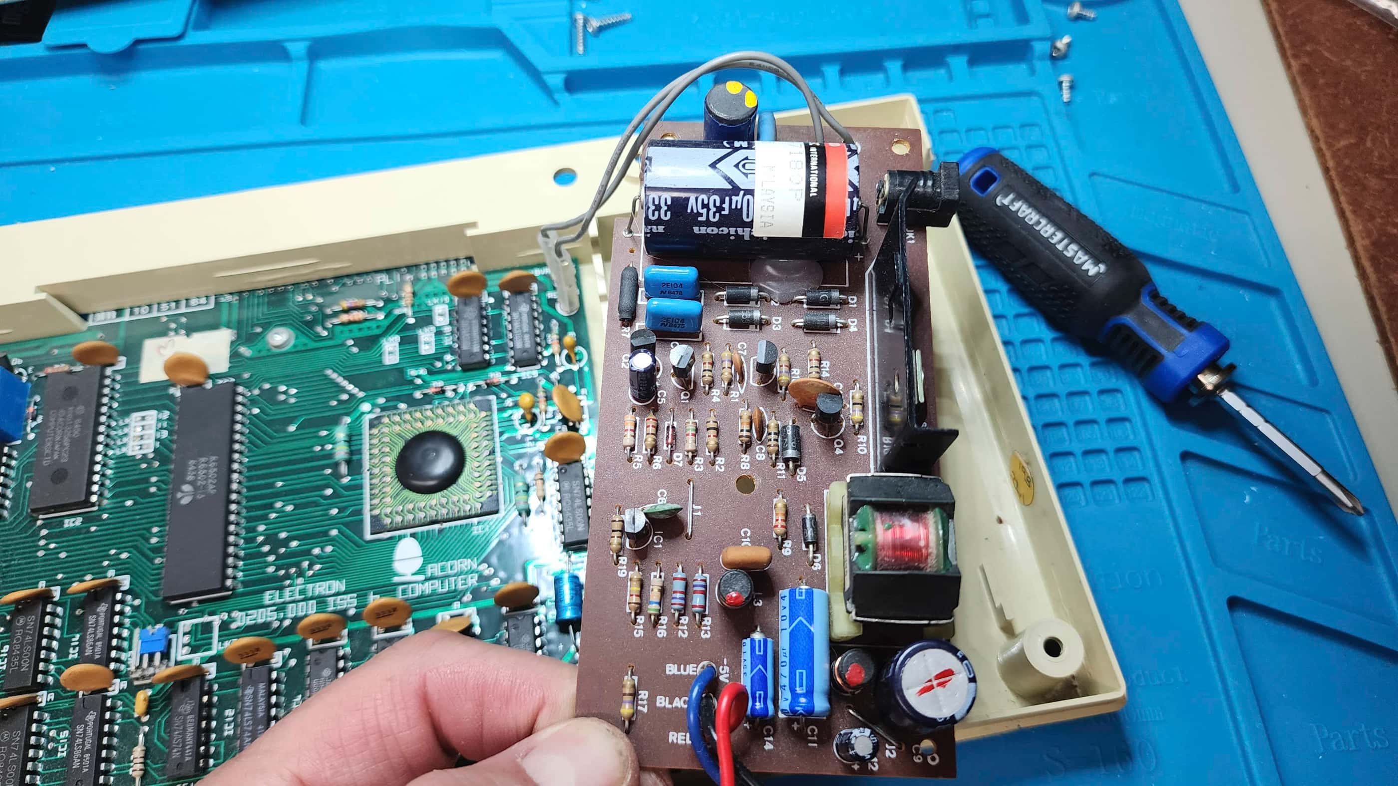
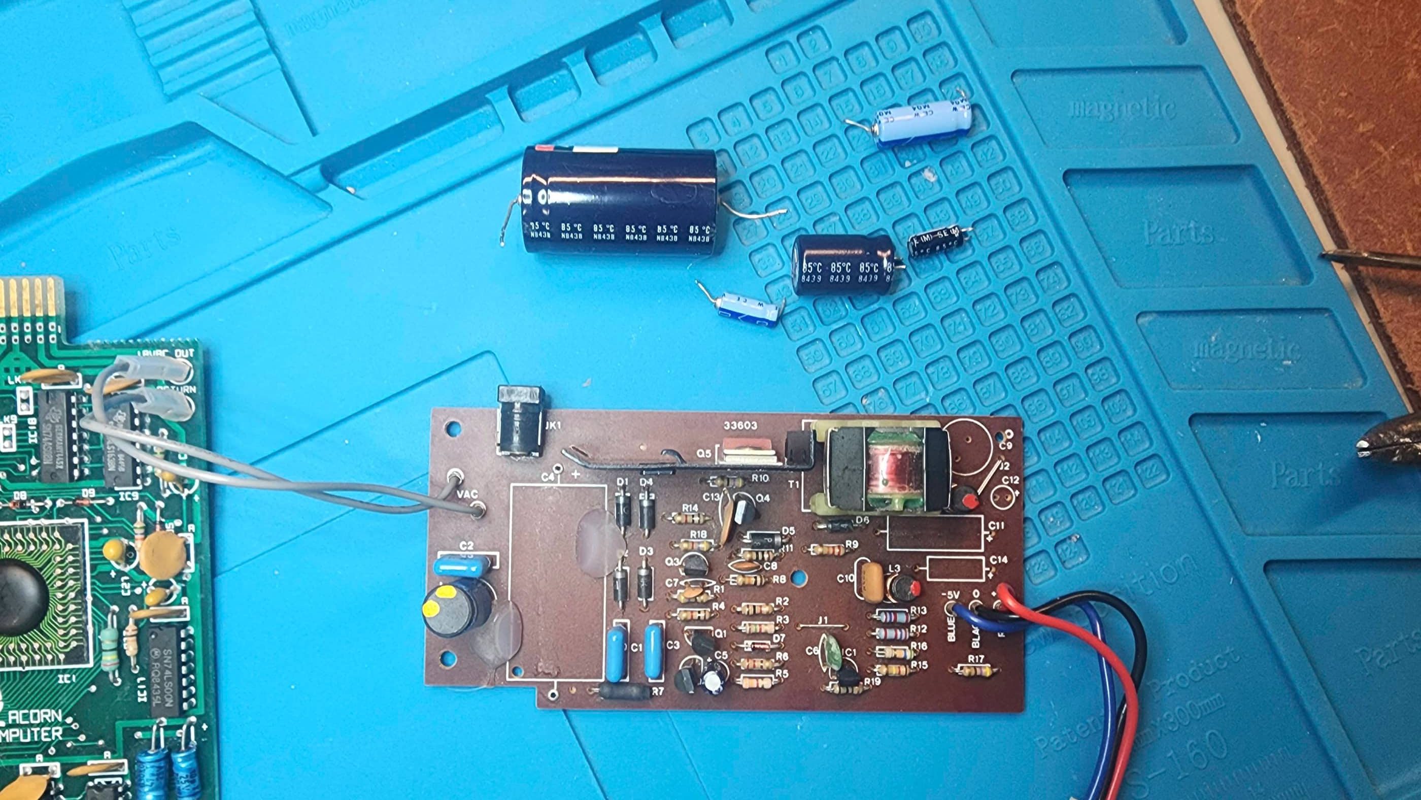
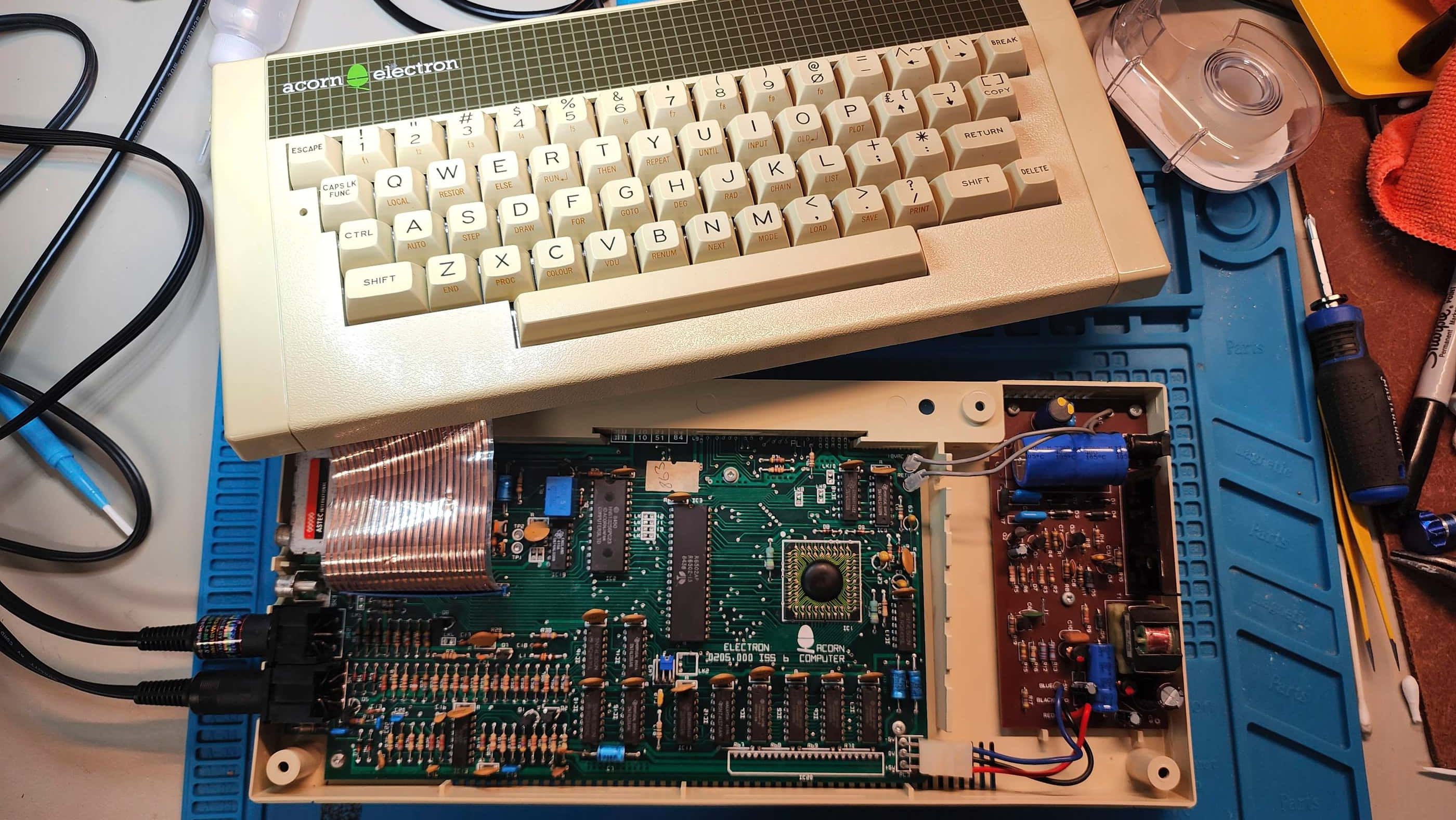
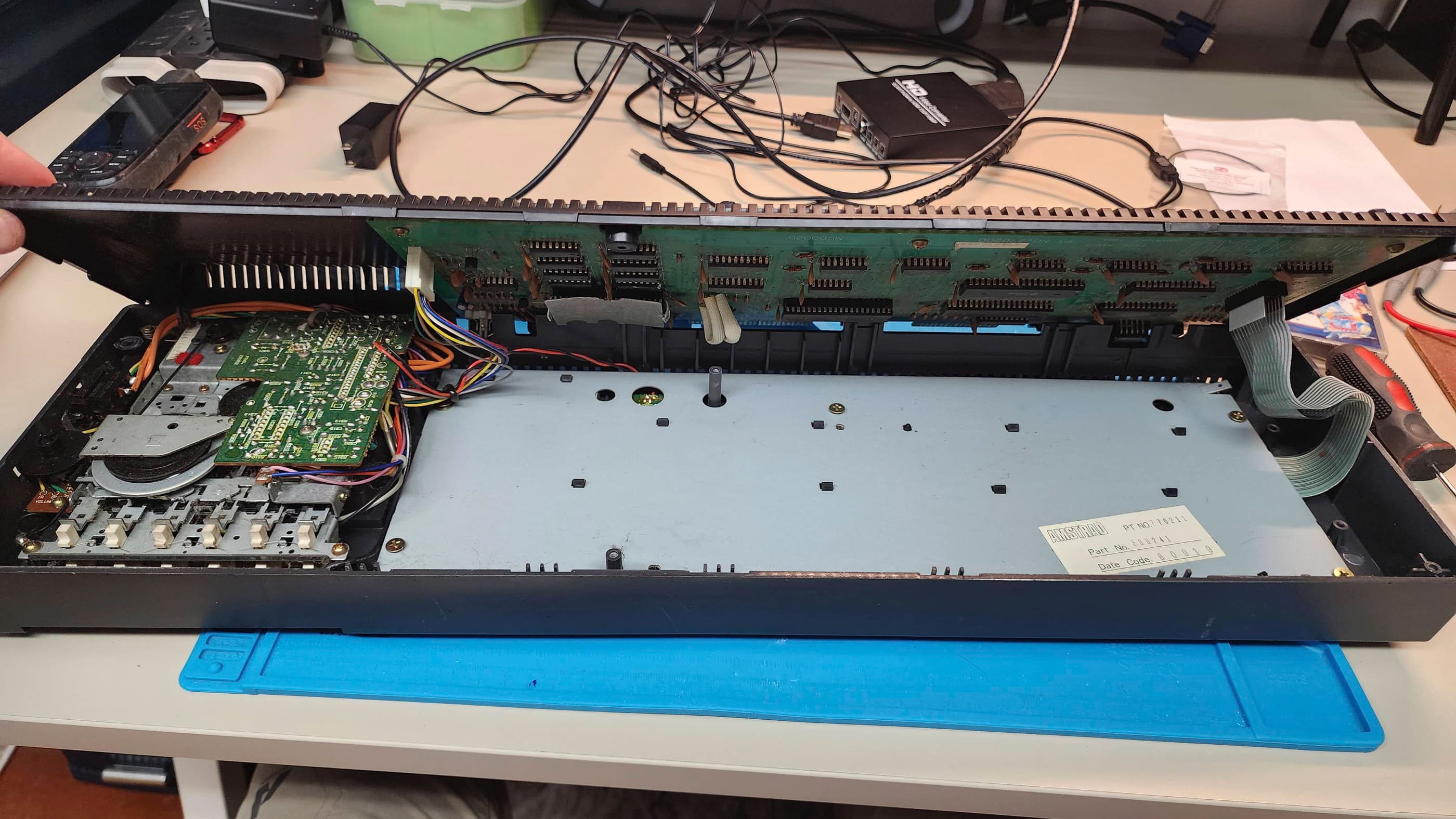
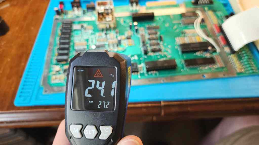
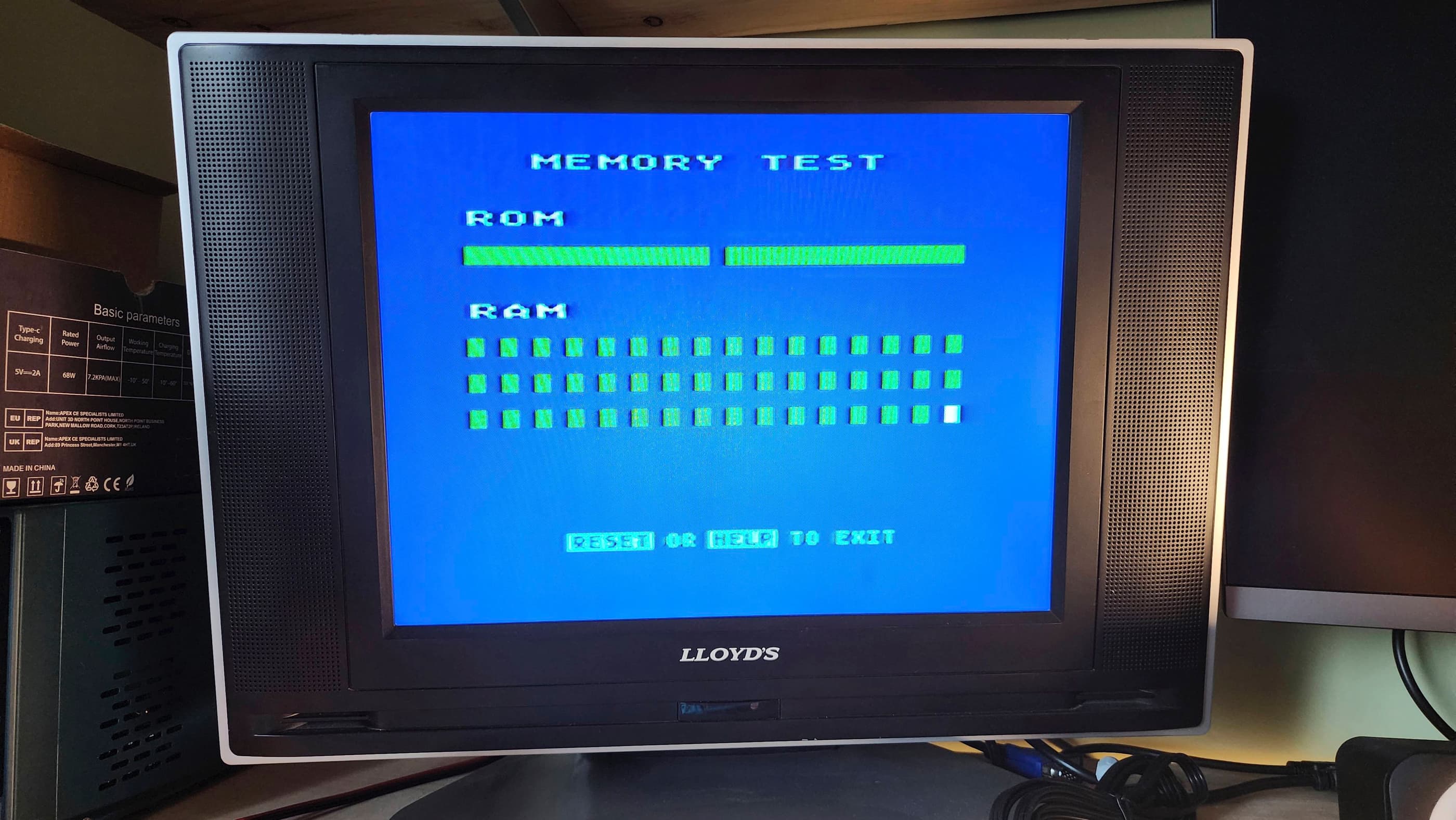
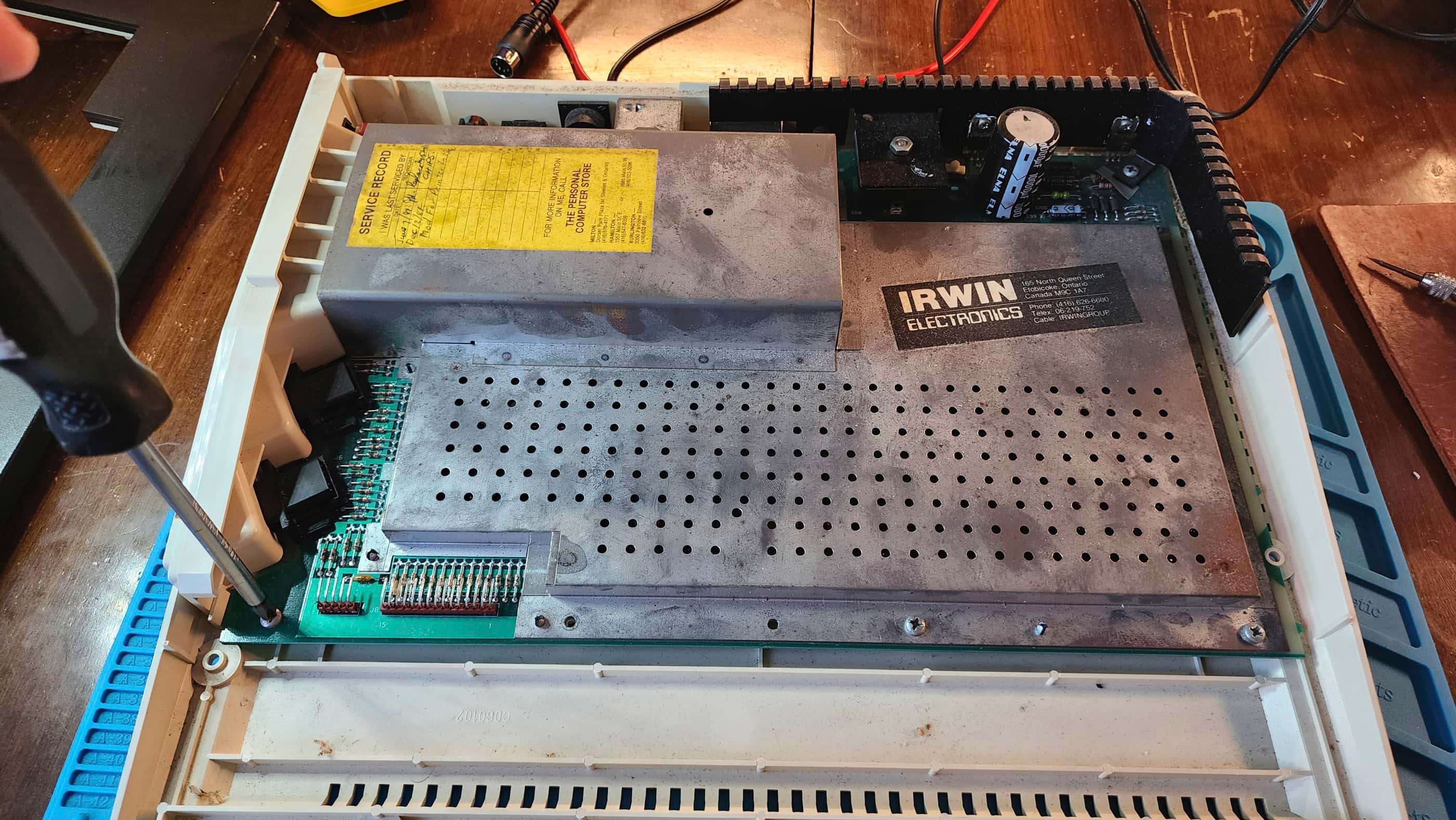
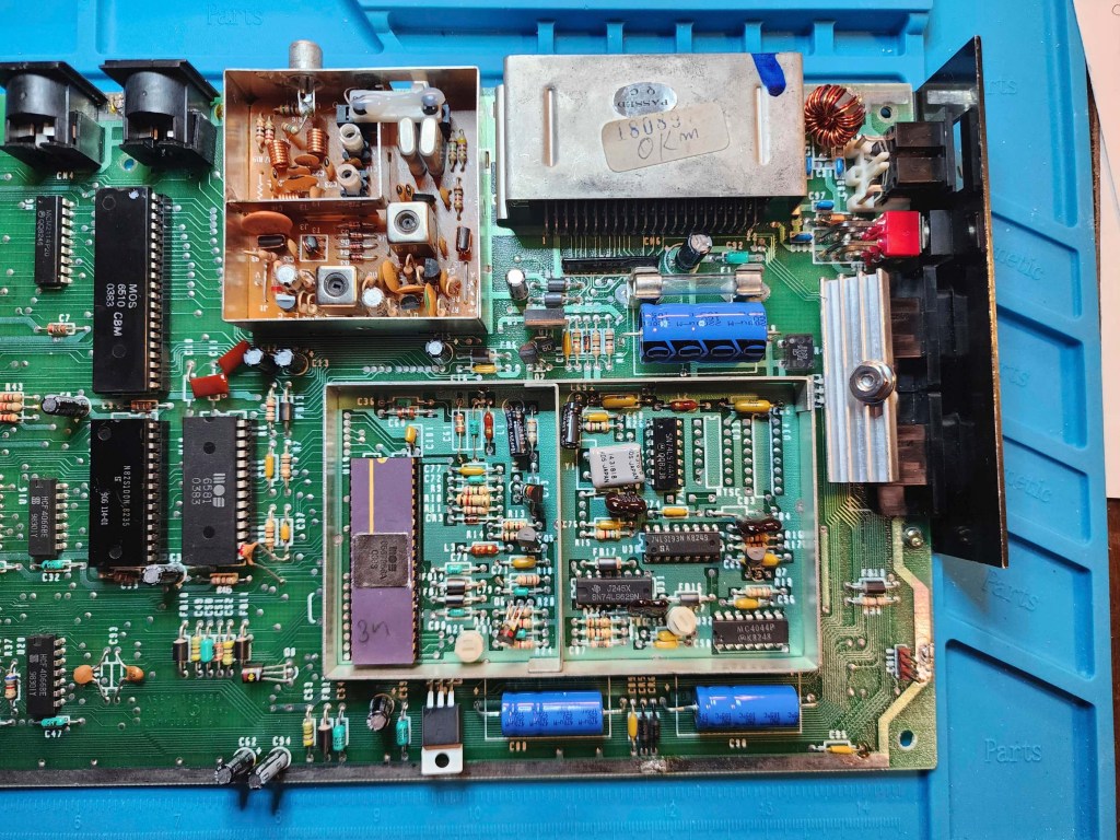
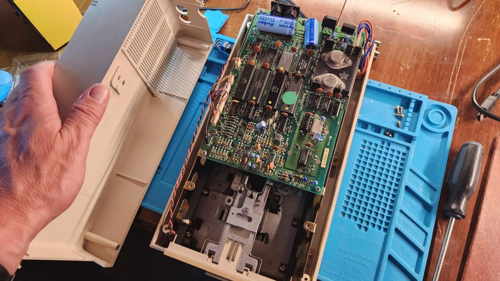
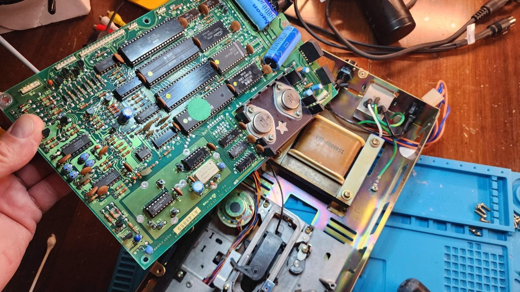
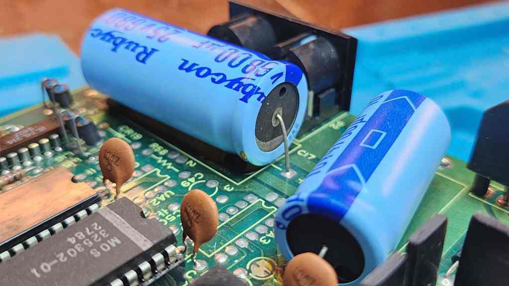
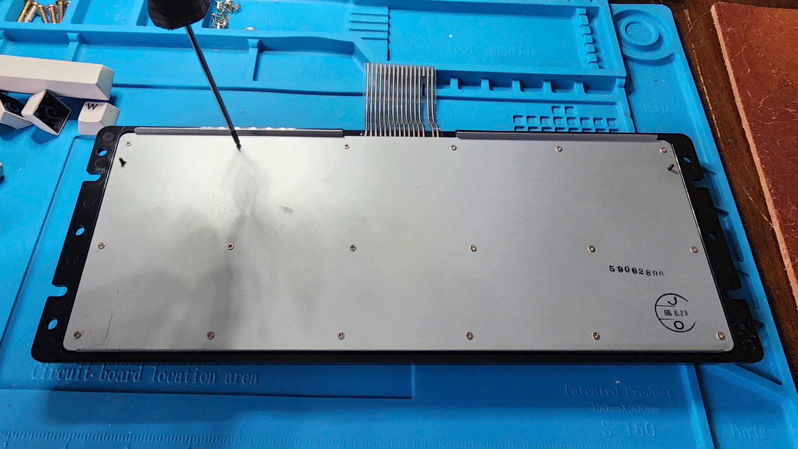
After disassembling the computer, I did my usual voltage testing and everything looked great. However, for internal switching PSUs, I usually perform a recap just to be on the safe side as I don’t know the history of the machine. Besides, after 43 years, the original caps might be getting long in the tooth and might not handle the load properly. So, I recapped the PSU using slightly high voltages than the originals. Once this was done, I tested the voltages and everything looked good. I then powered the computer on to see the display, and it too was great.
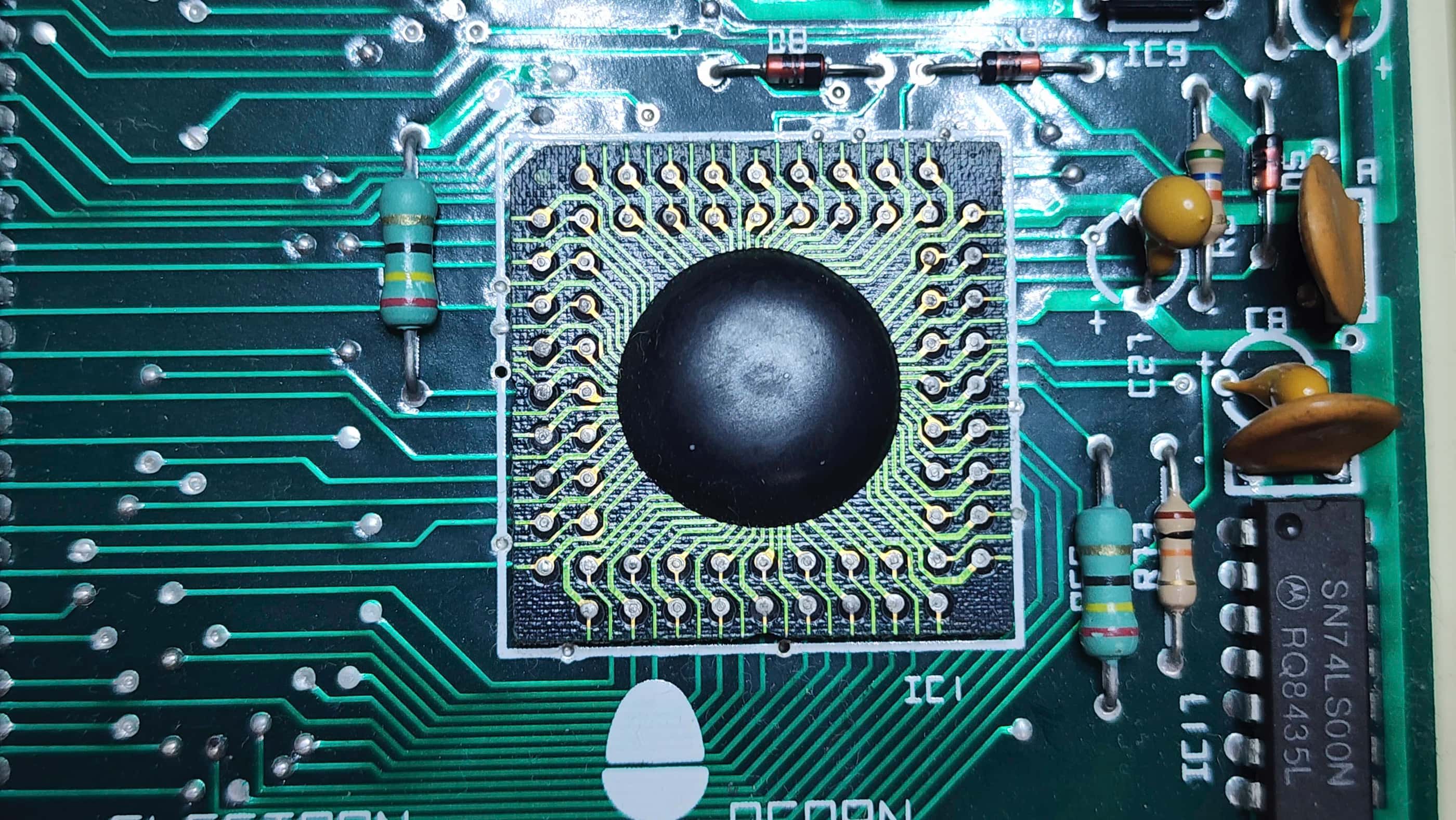
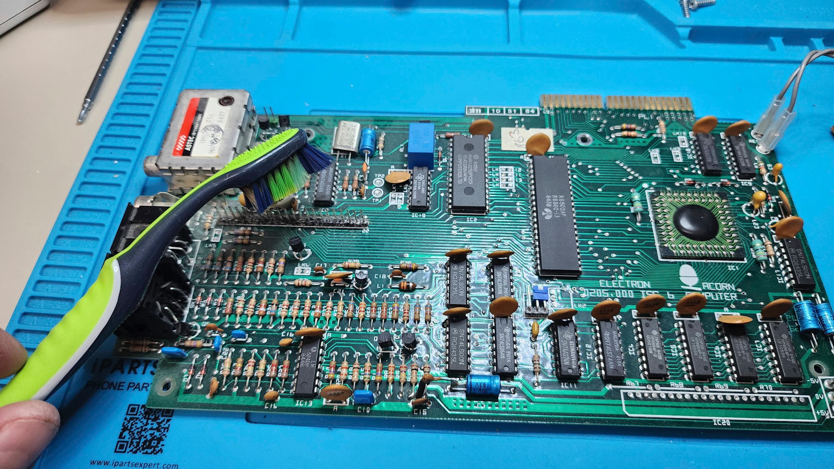
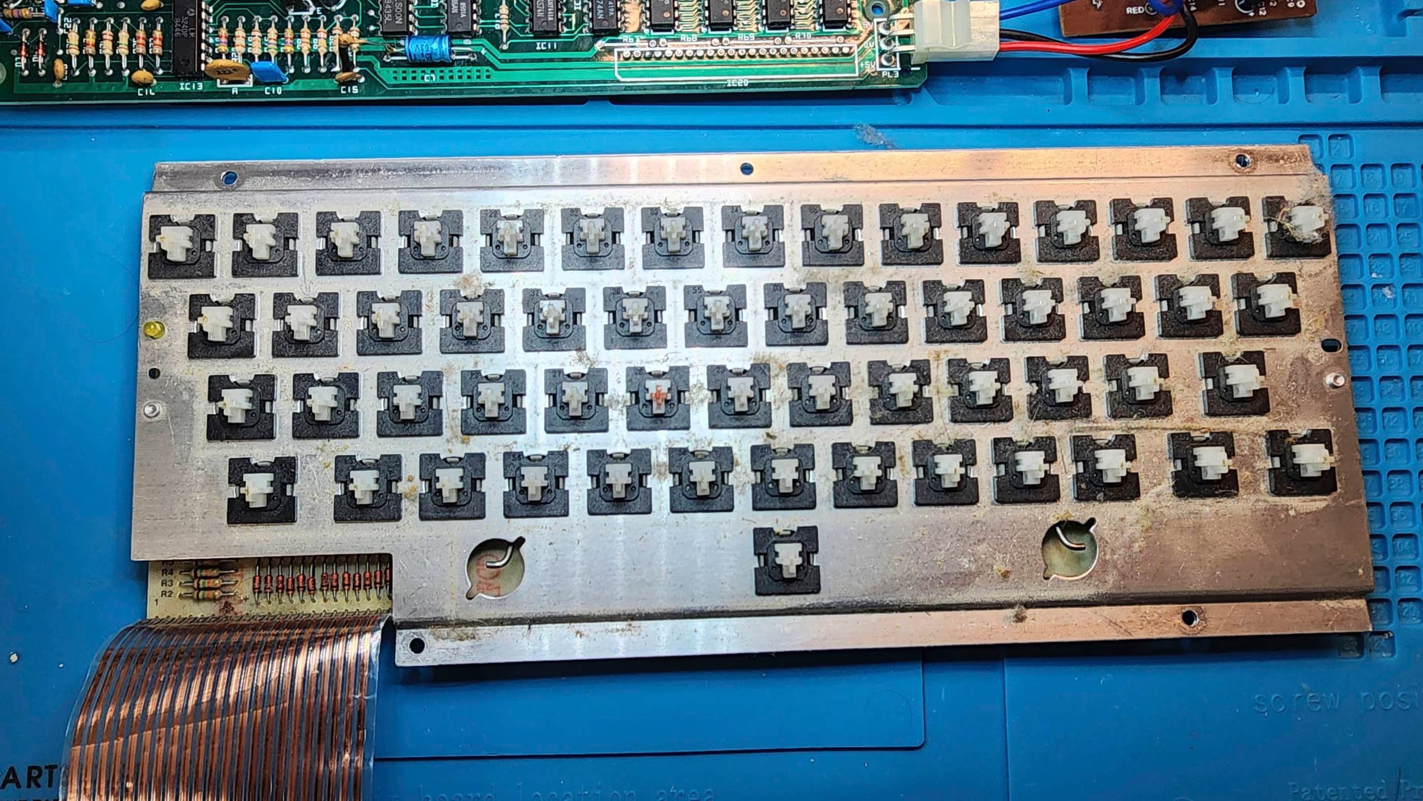
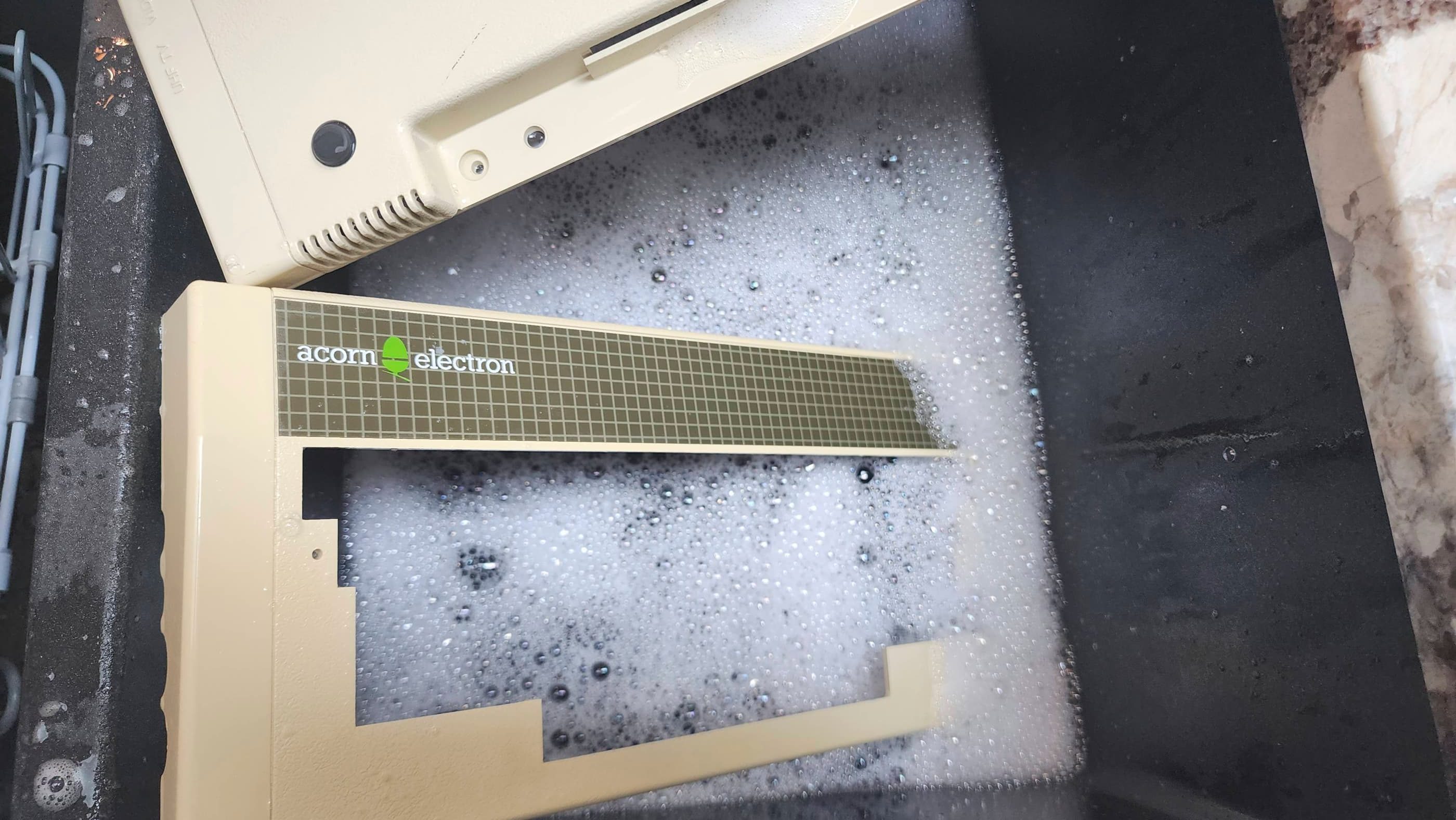
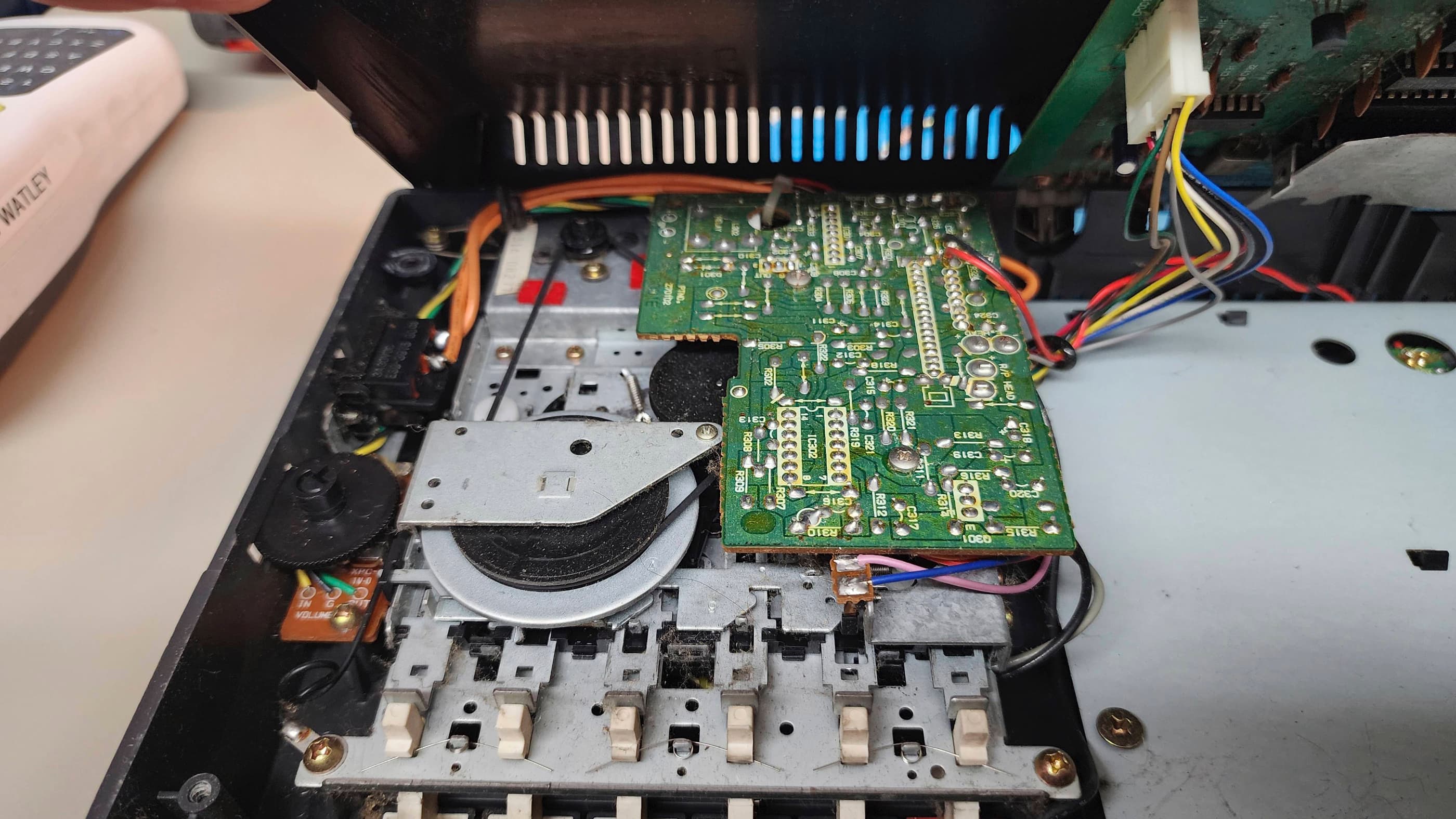
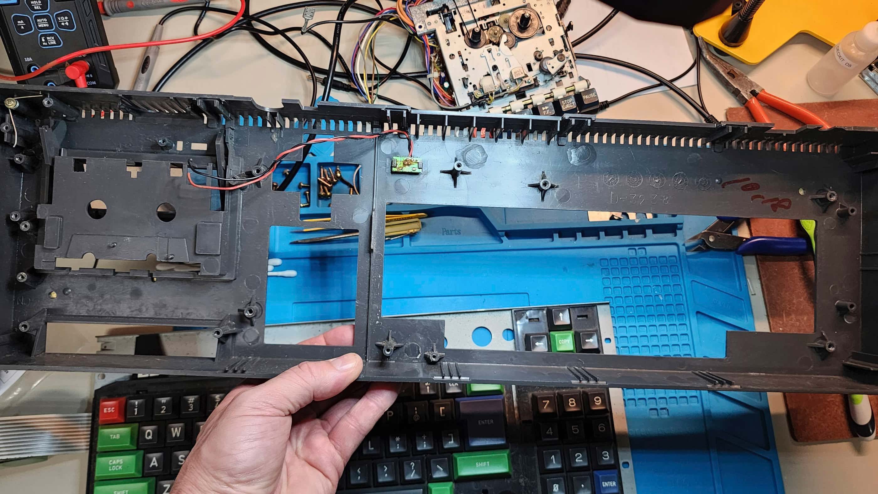
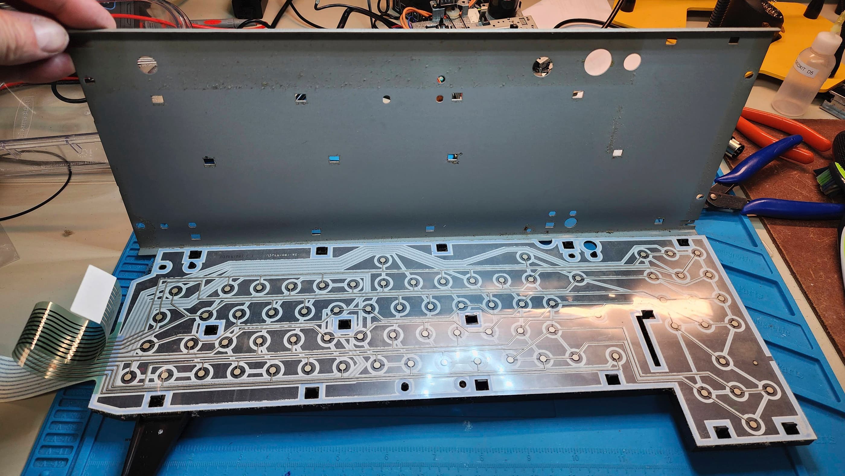
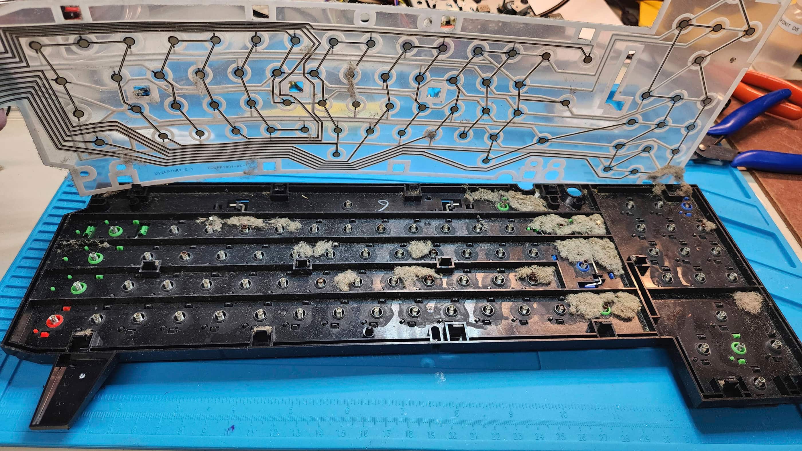
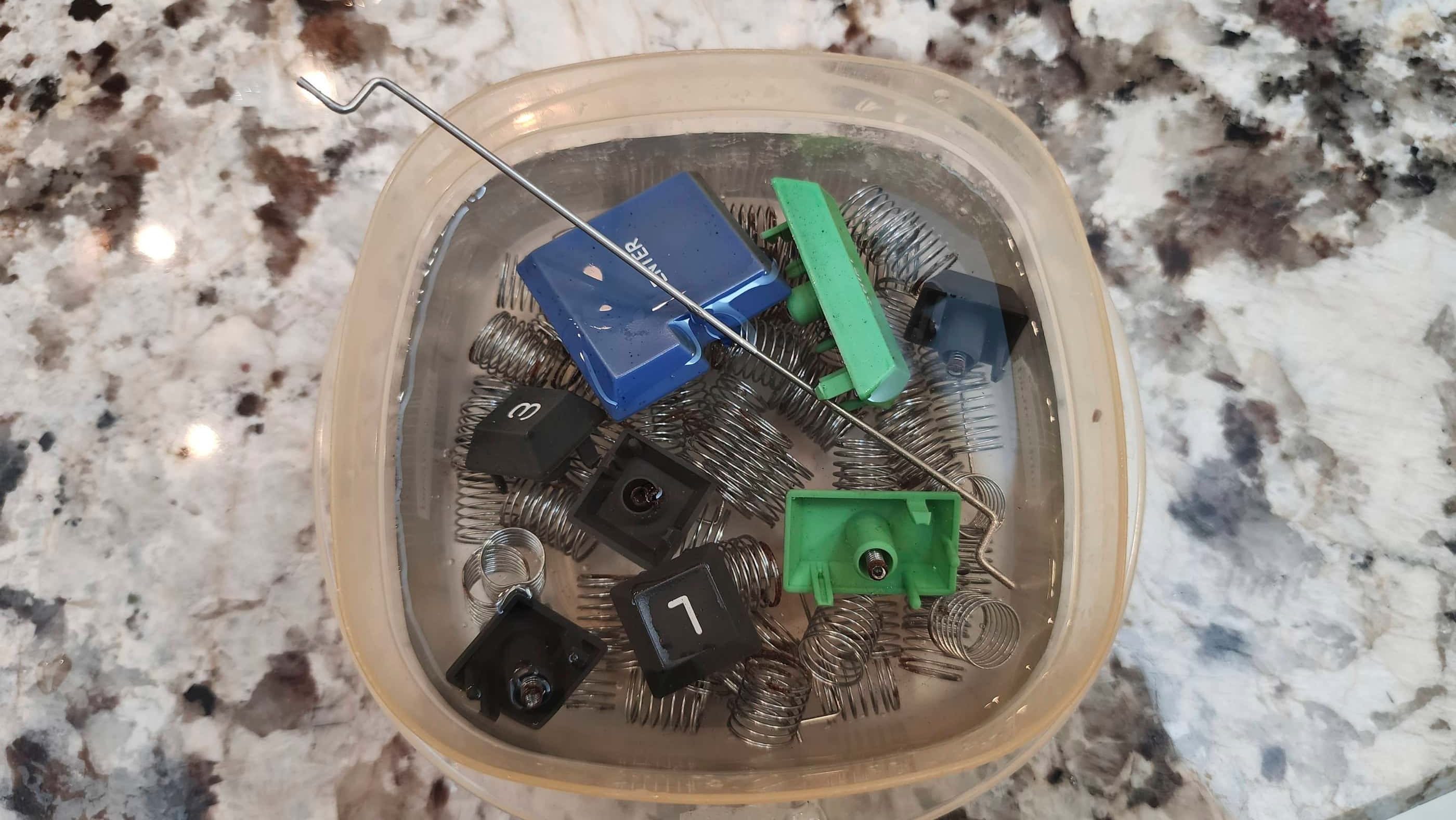
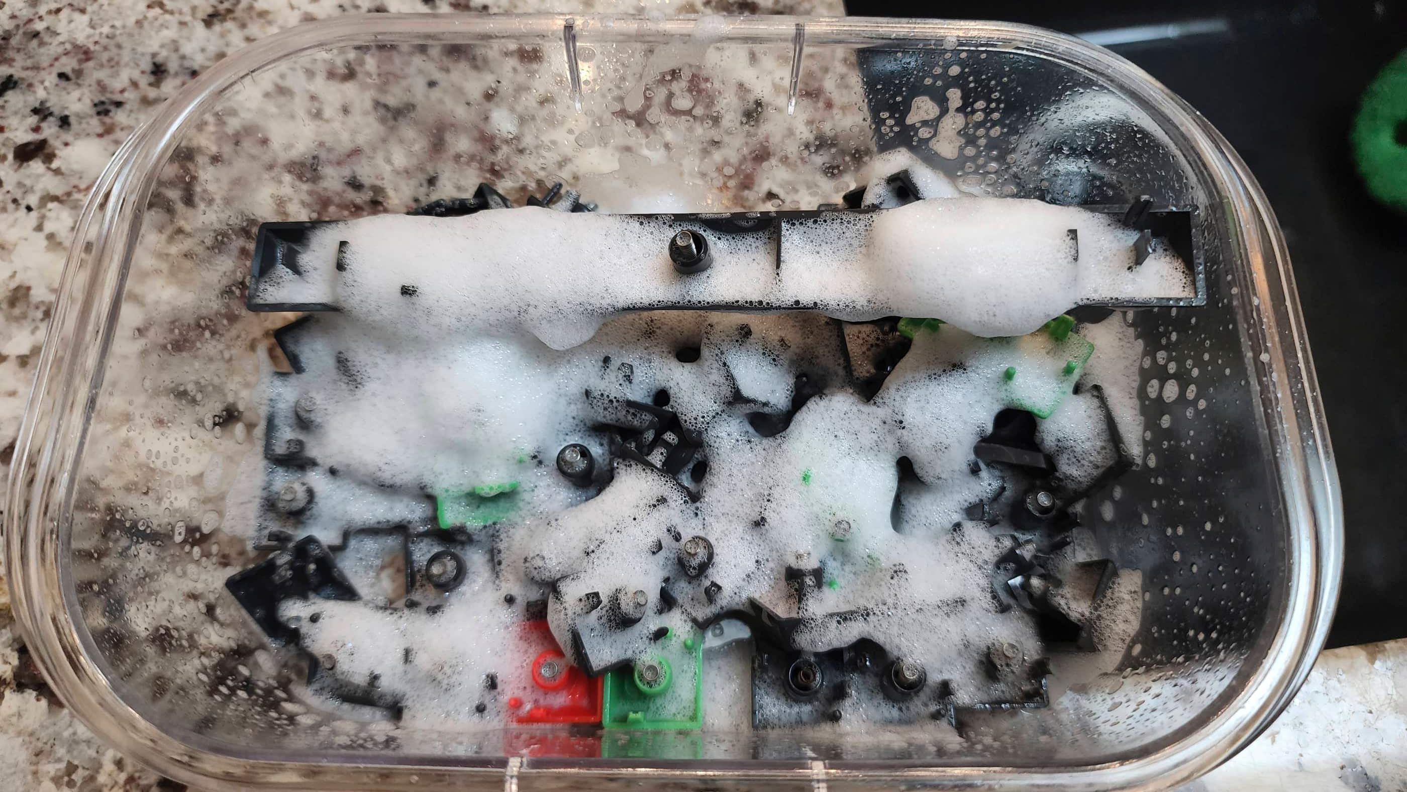
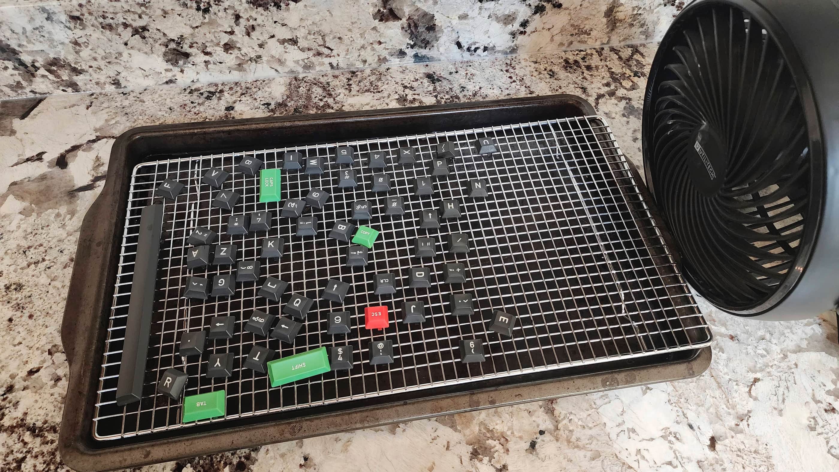
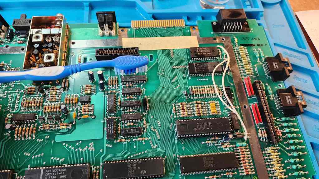
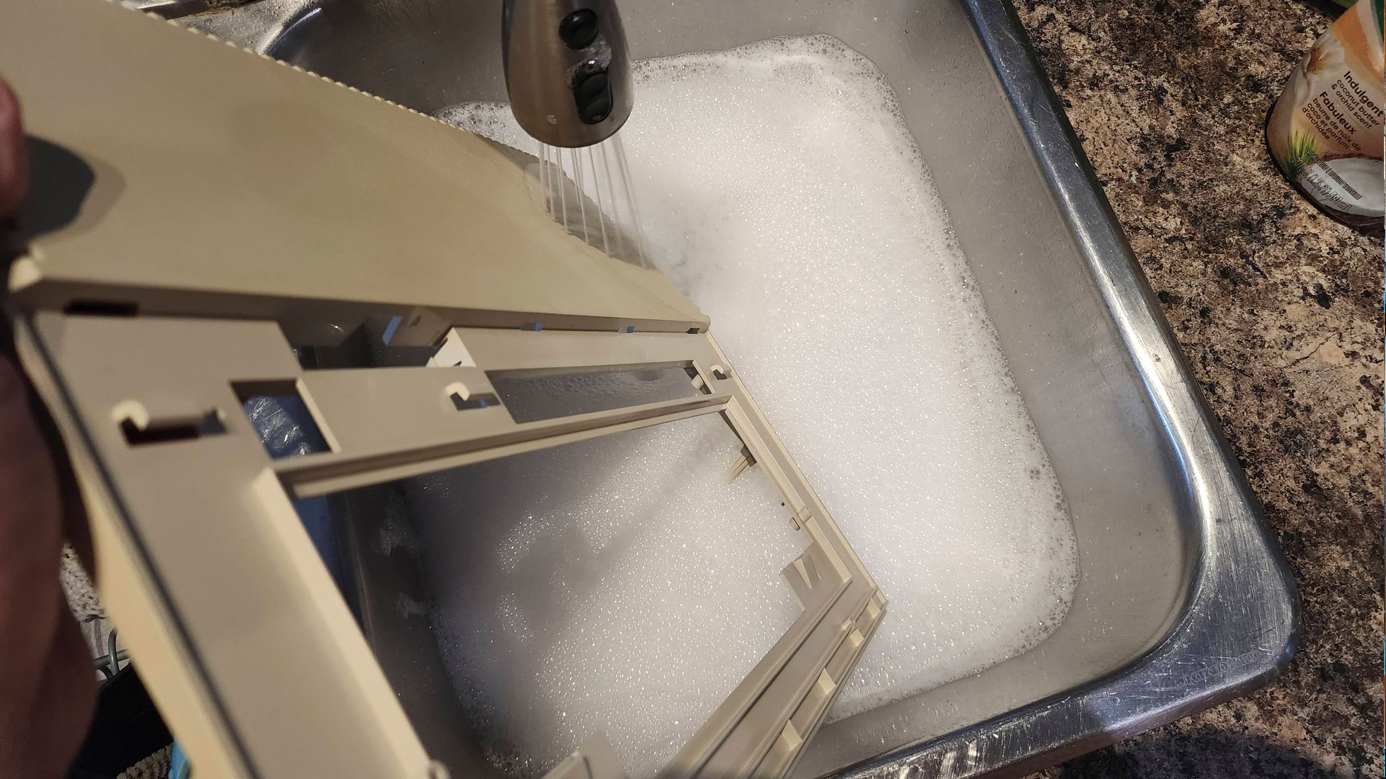
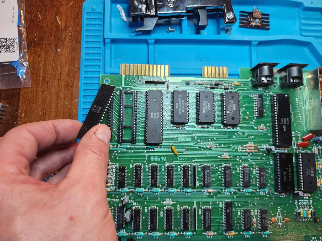
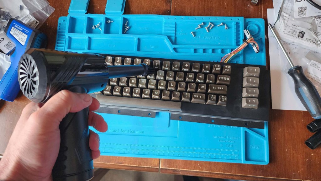
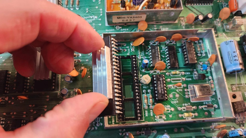
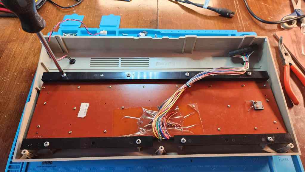
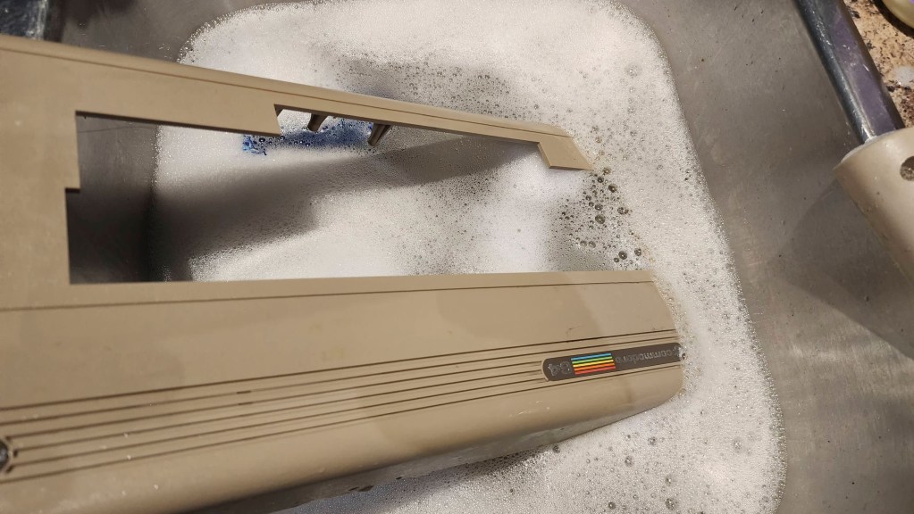
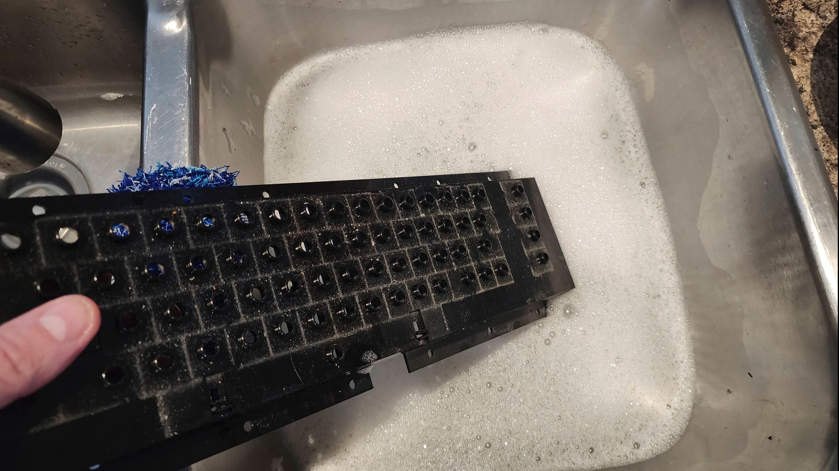
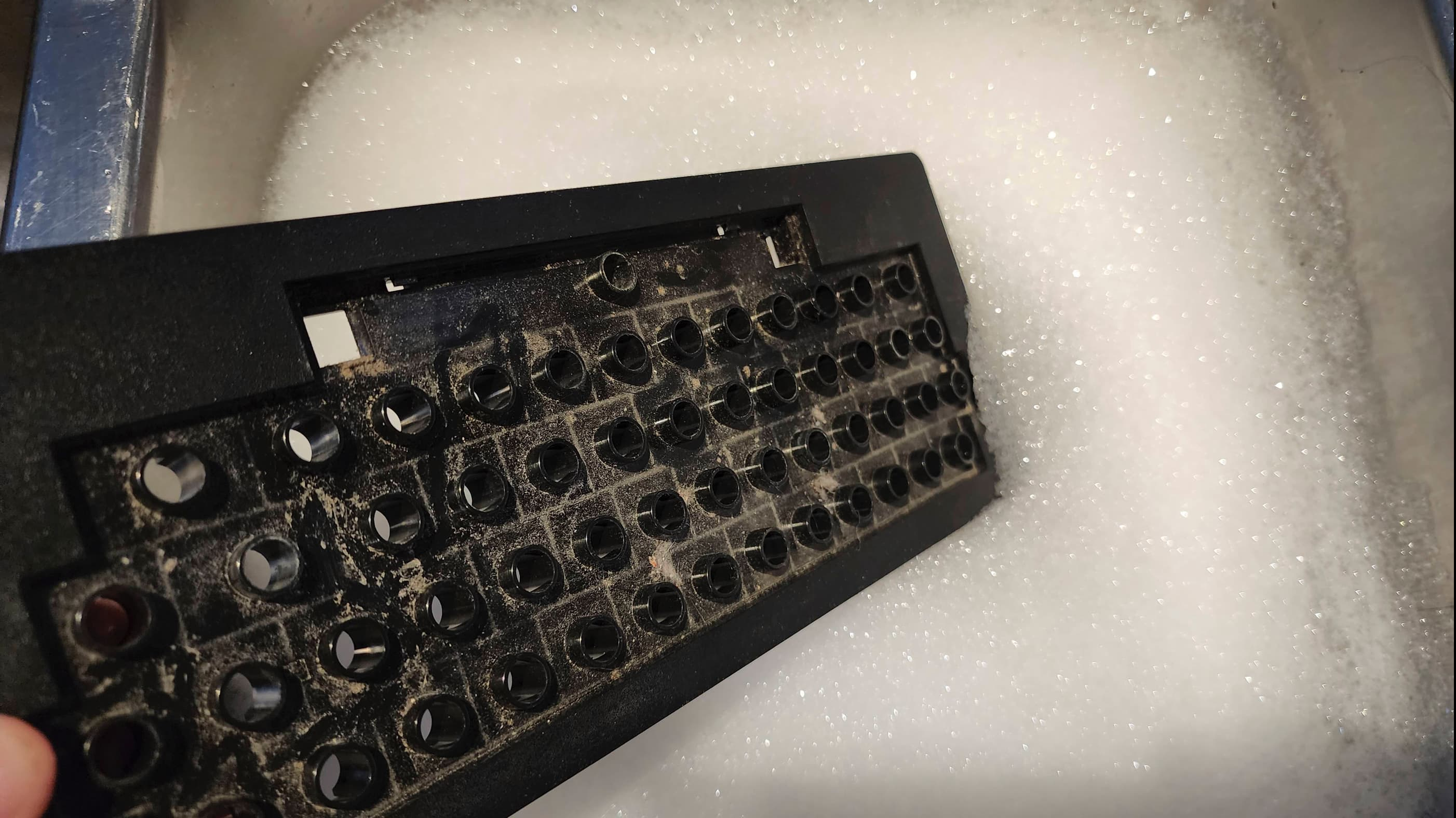
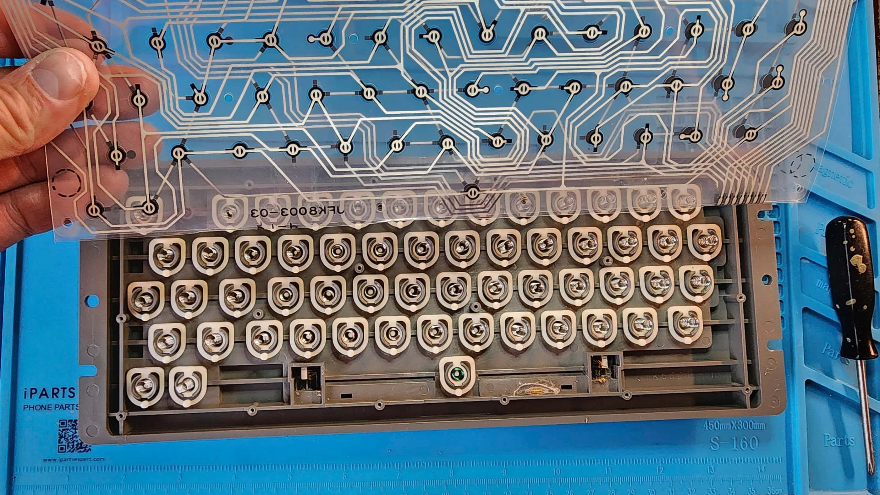
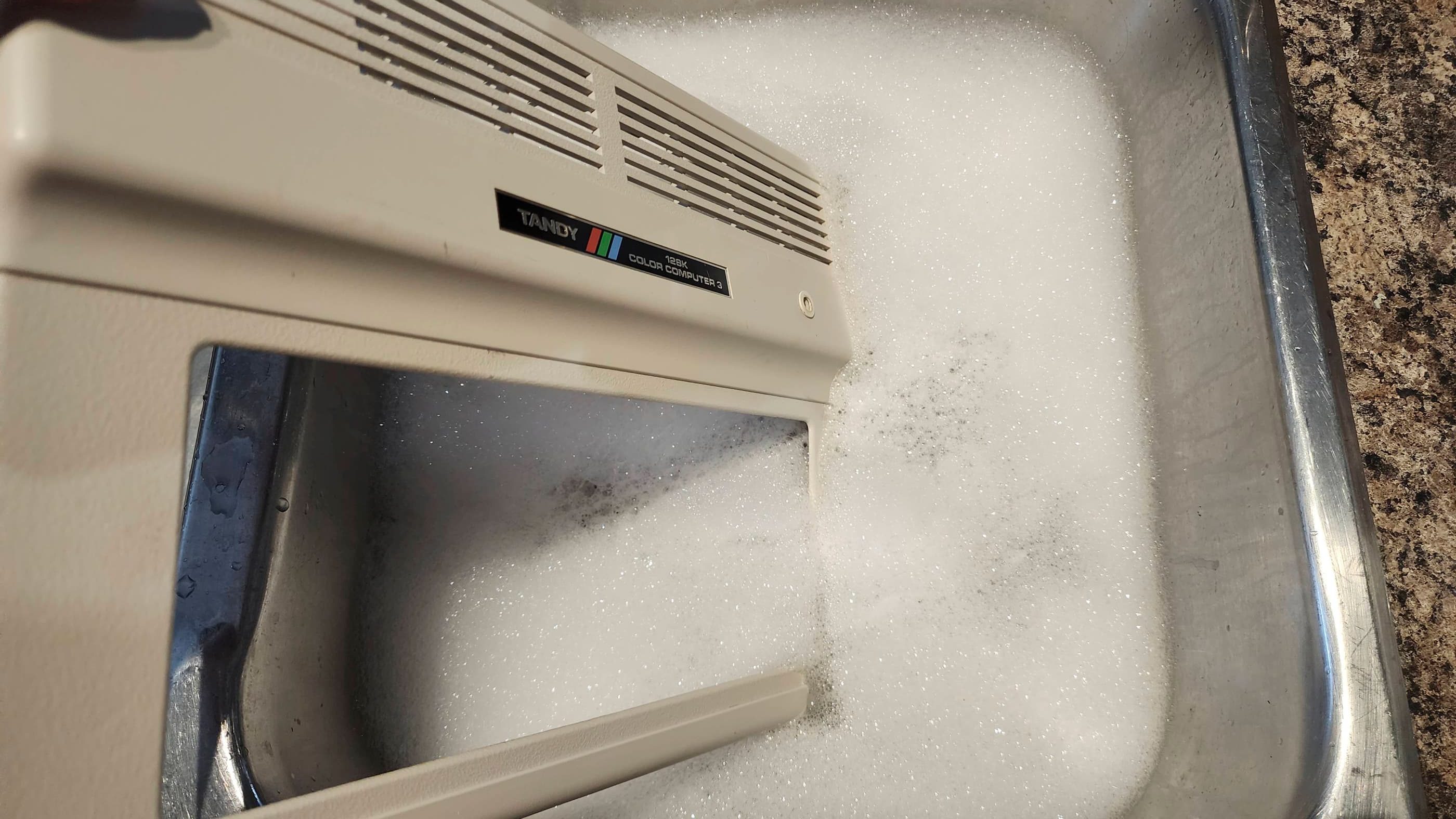
After giving the board a thorough clean with IPA along with placing a low profile heatsink on the 6502, I began to work on the keyboard. Once I had the key caps removed, I soaked them along with the top and bottom halves of the case in Dawn Powerwash. It was almost mesmerizing to watch 43 years of grime melt off. 🙂 After soaking for a long period of time, I then washed and dried everything.
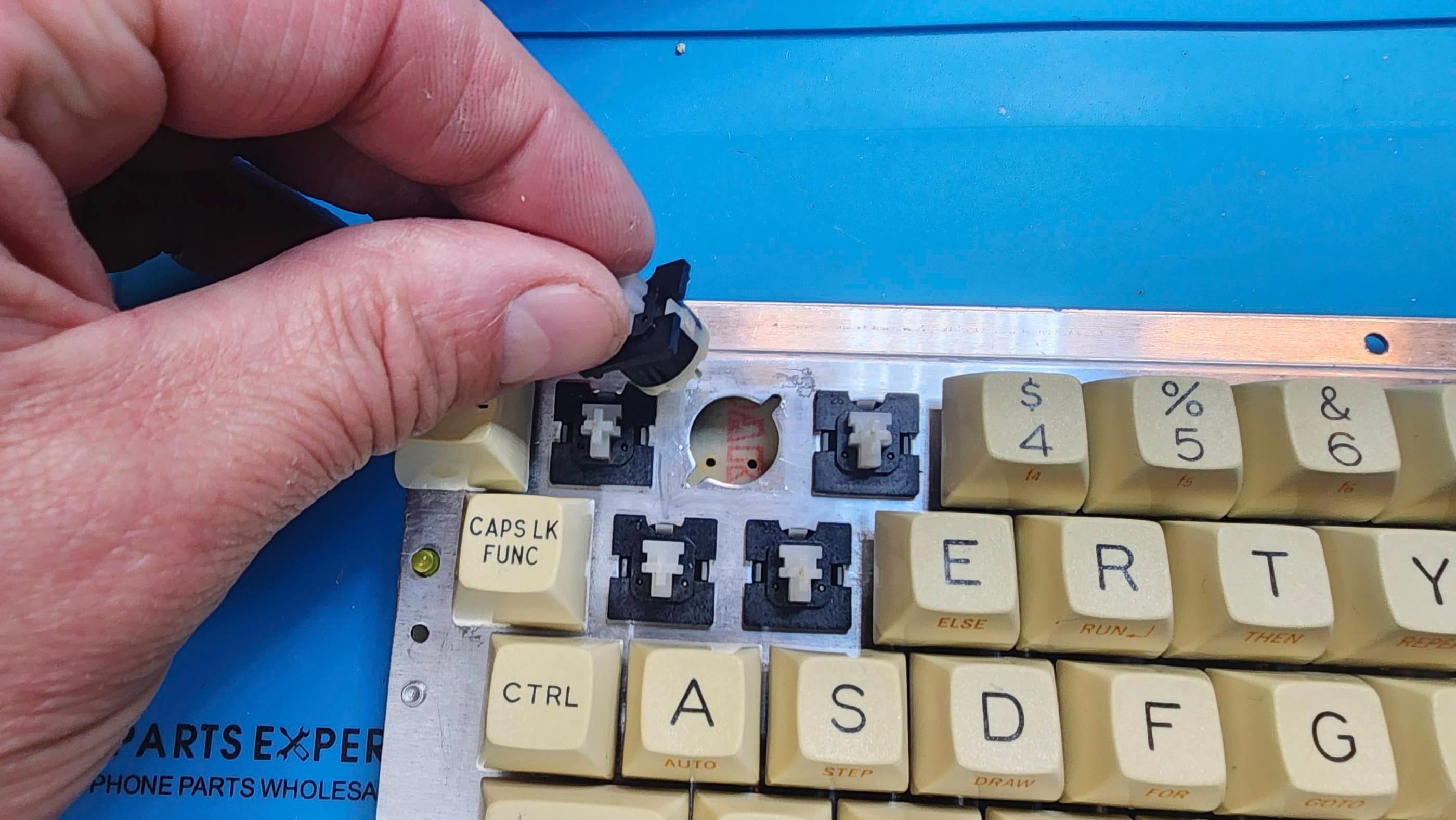
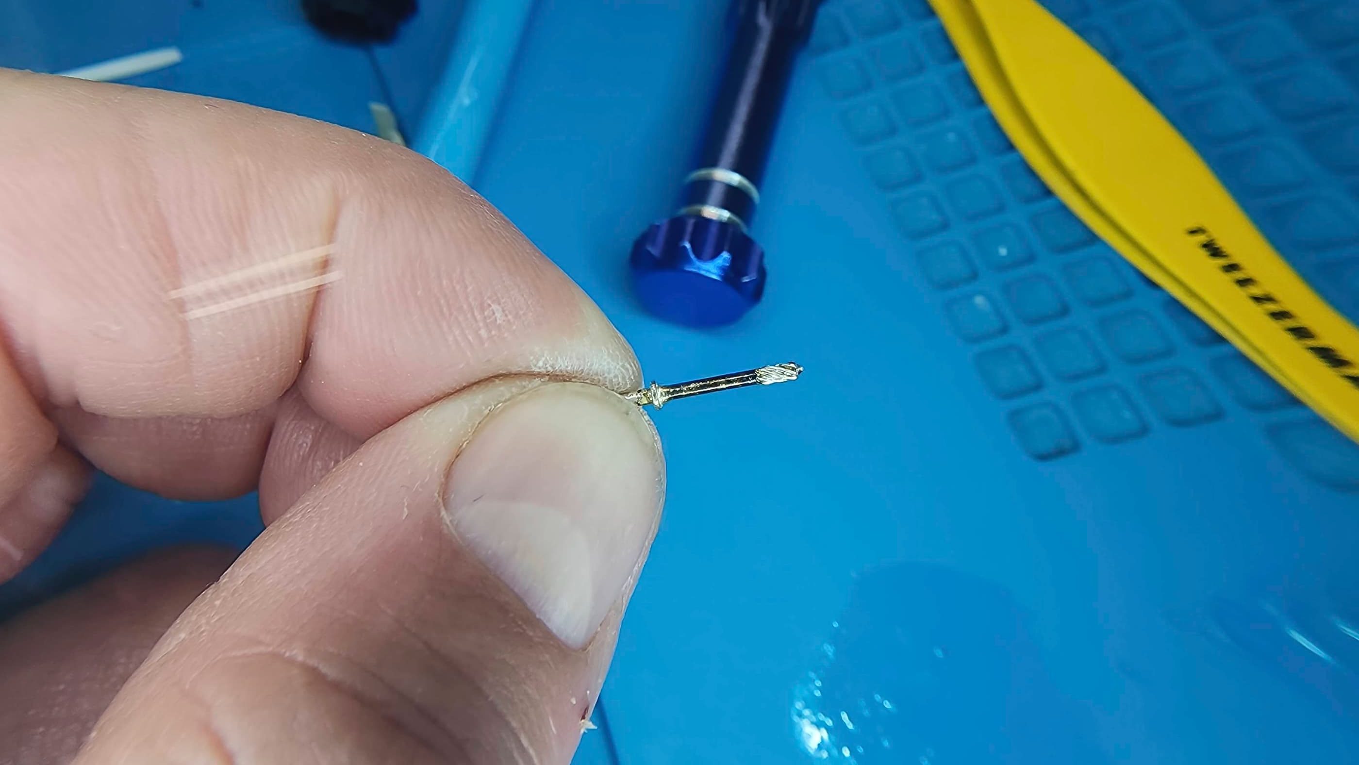
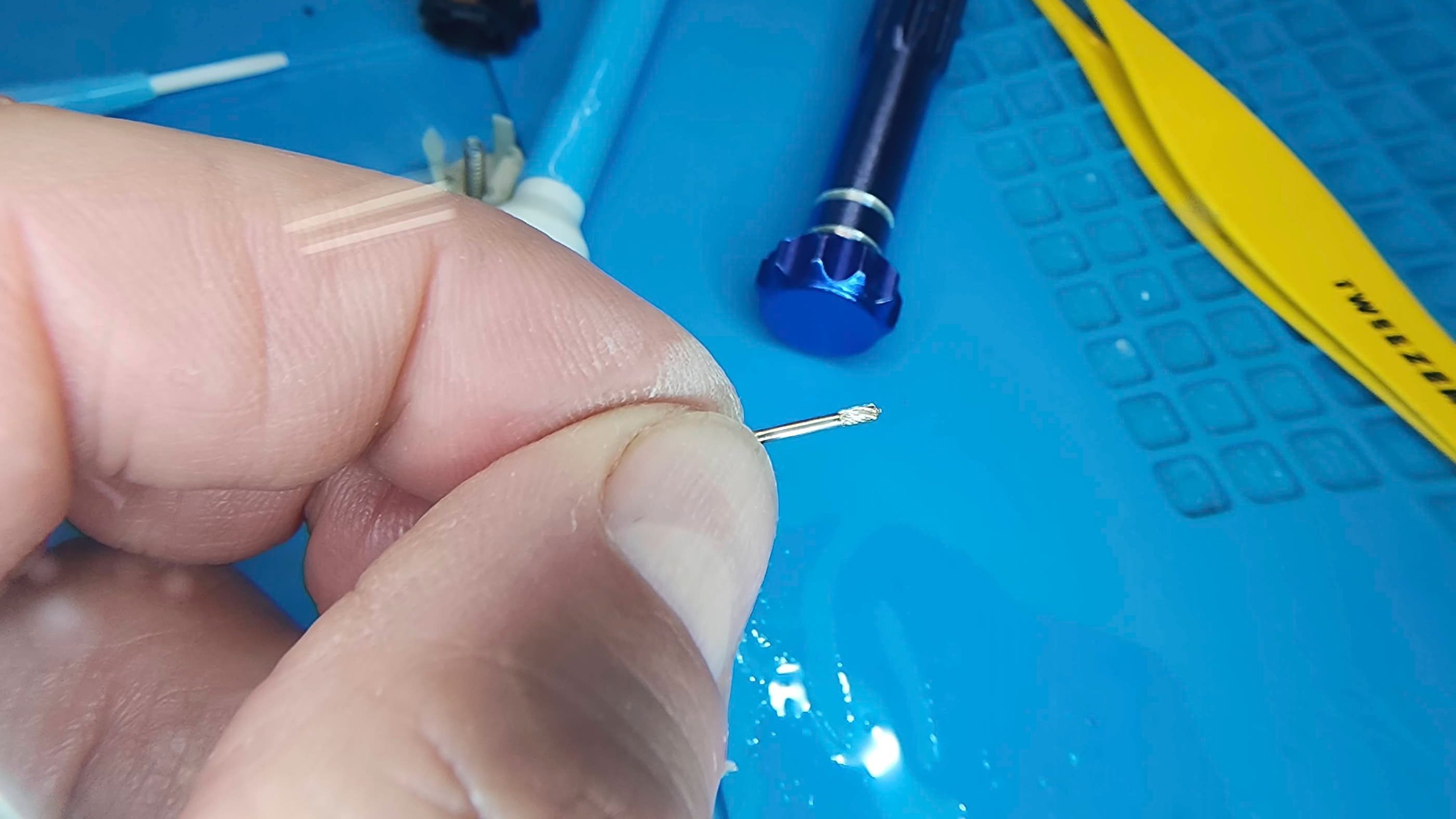
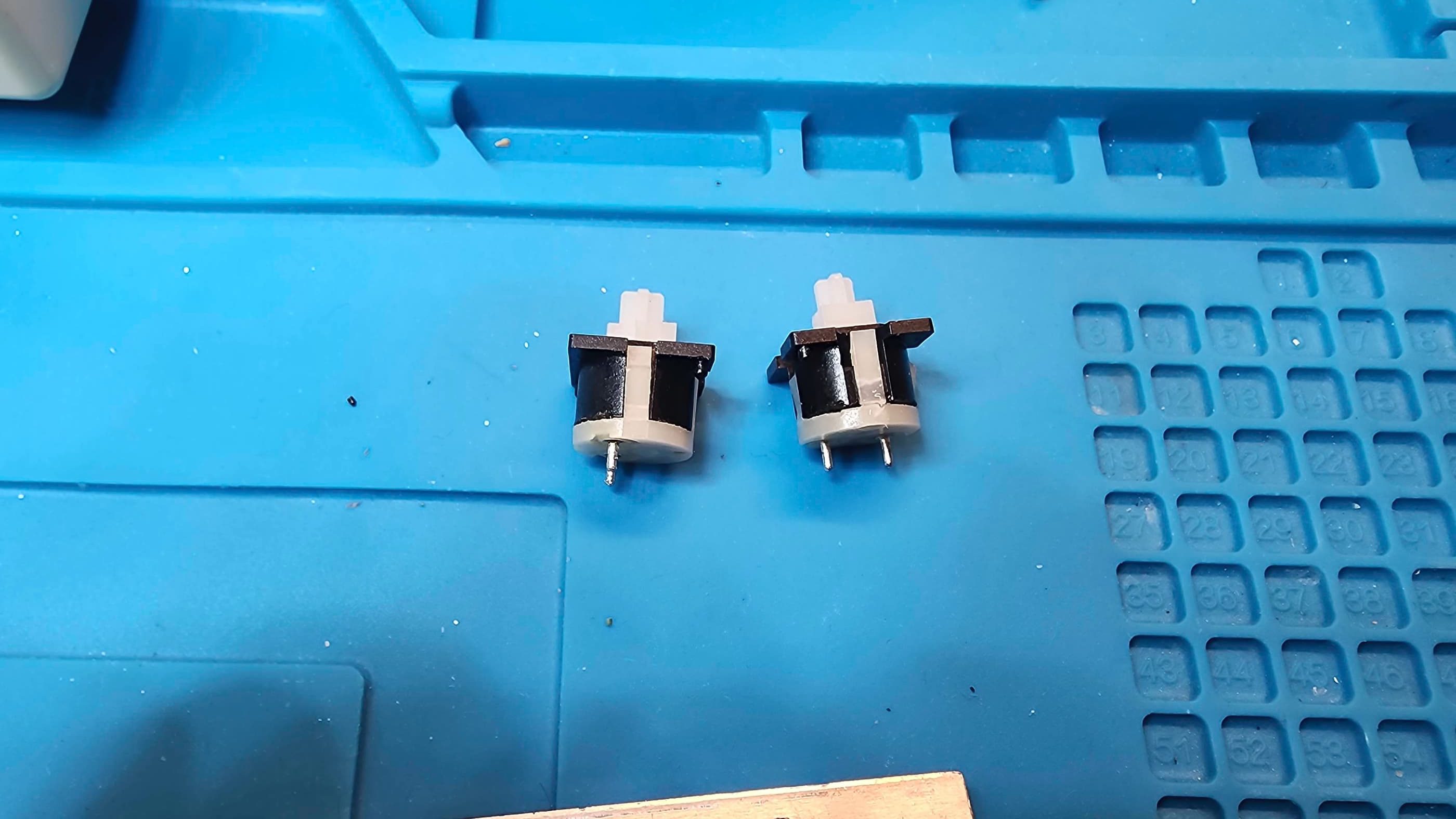
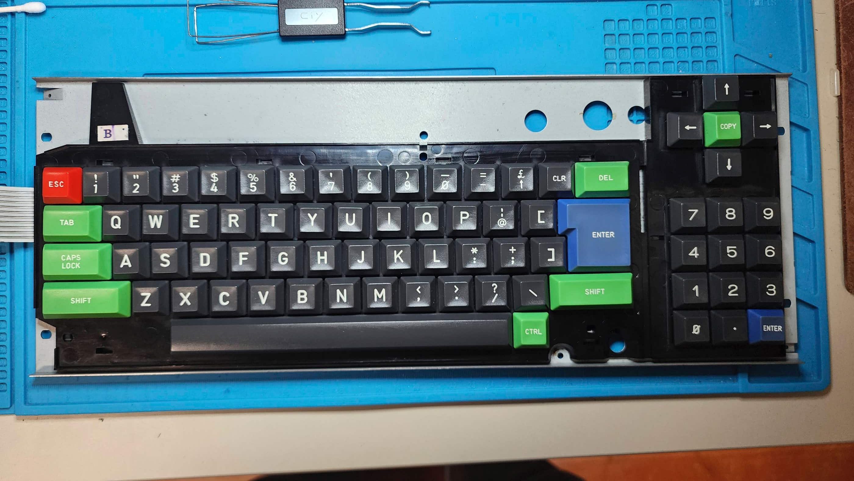
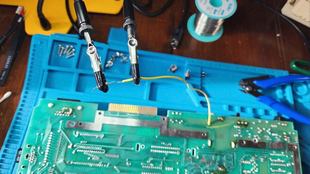
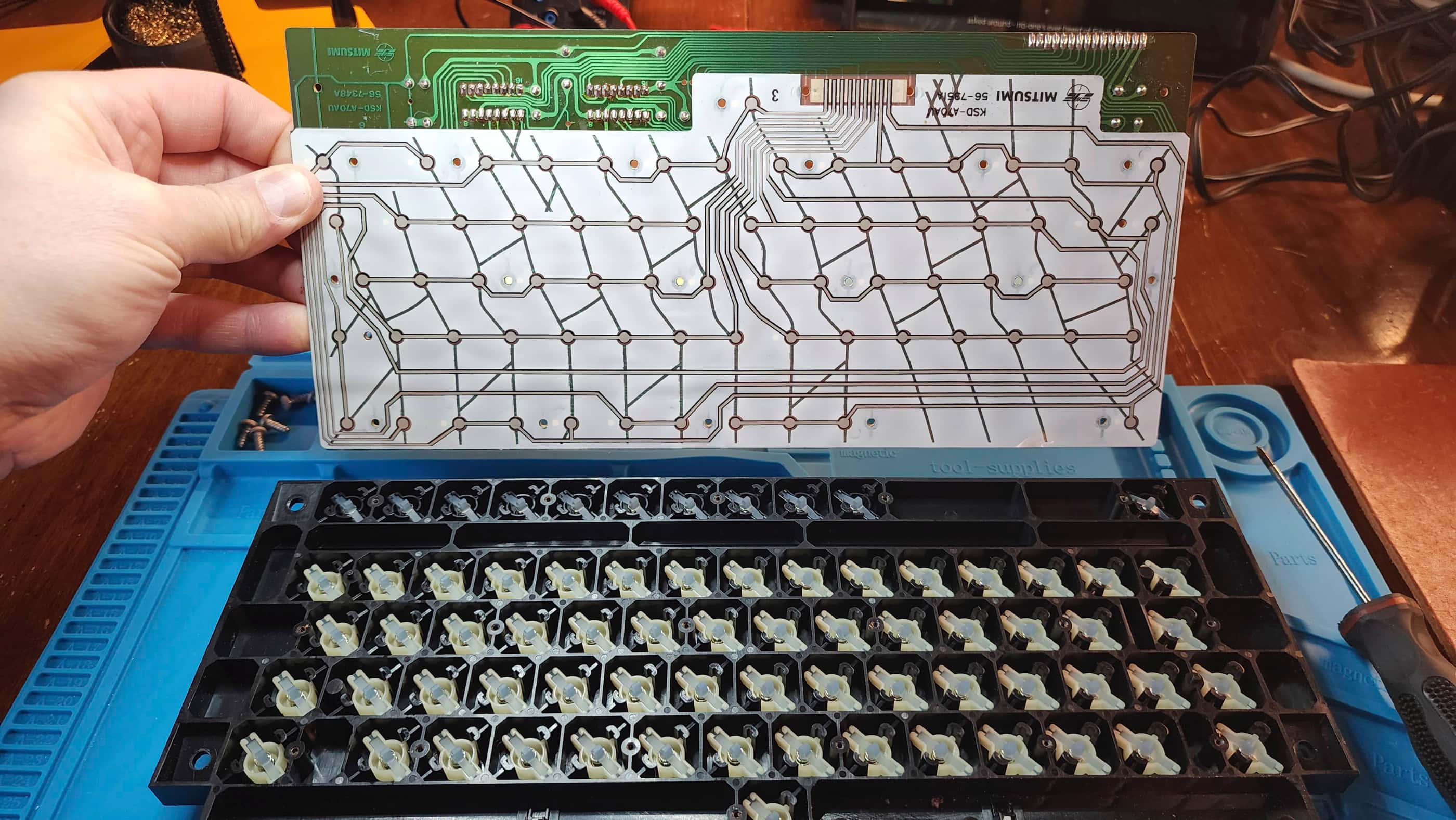
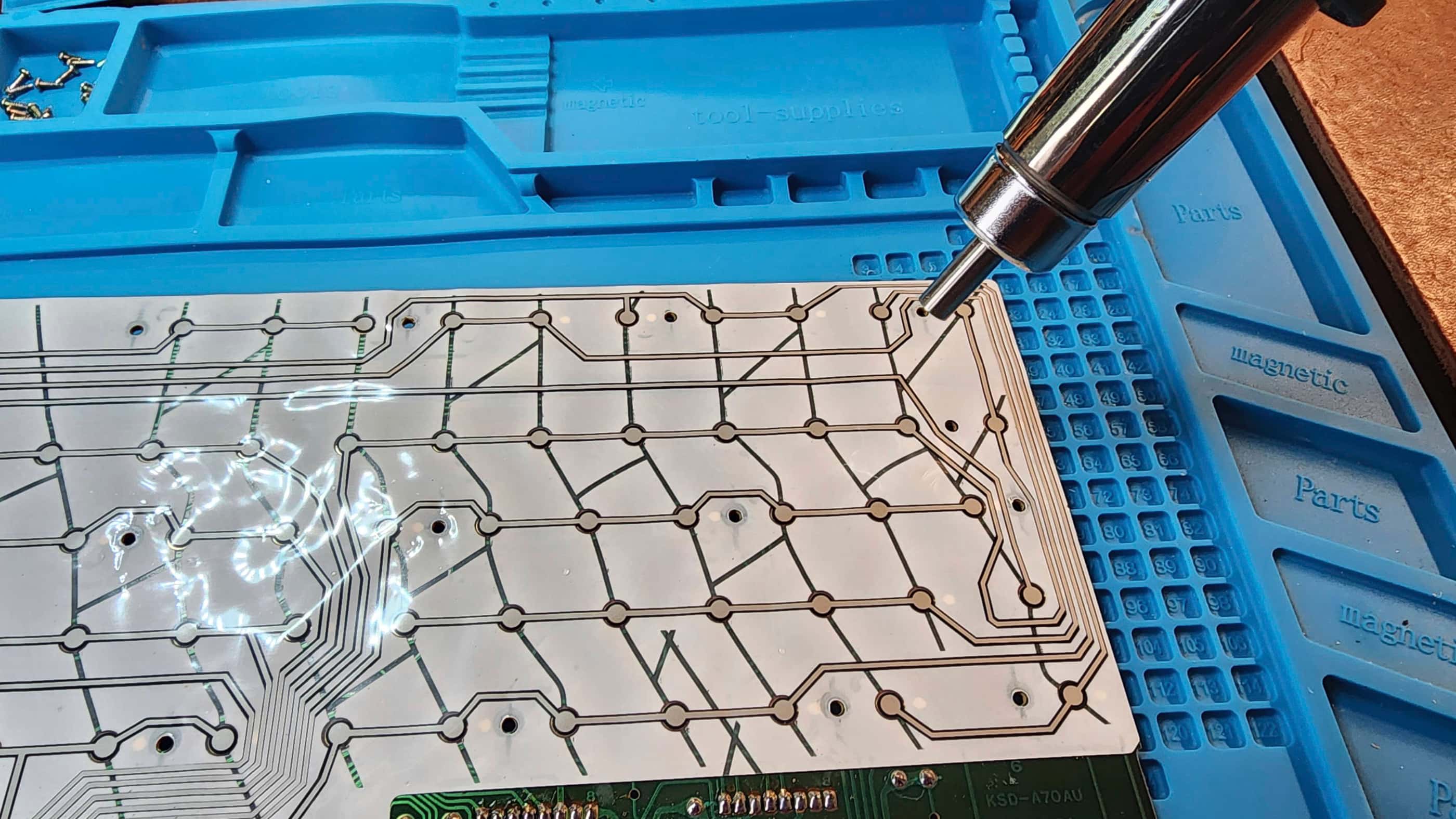
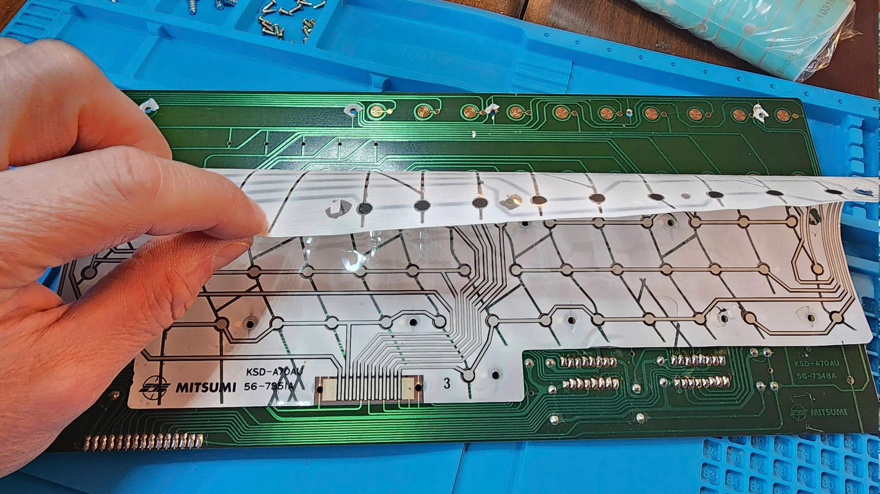
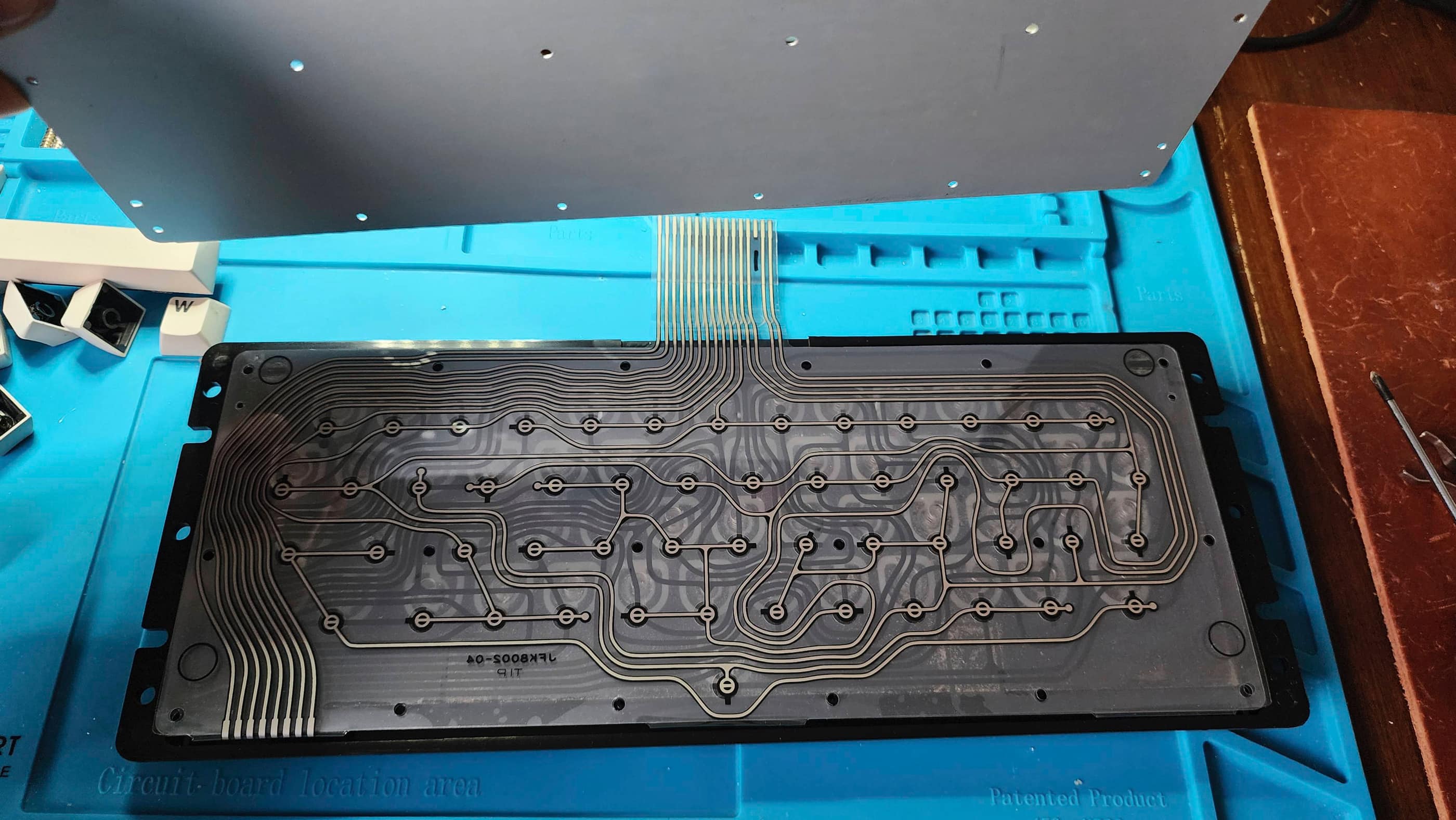
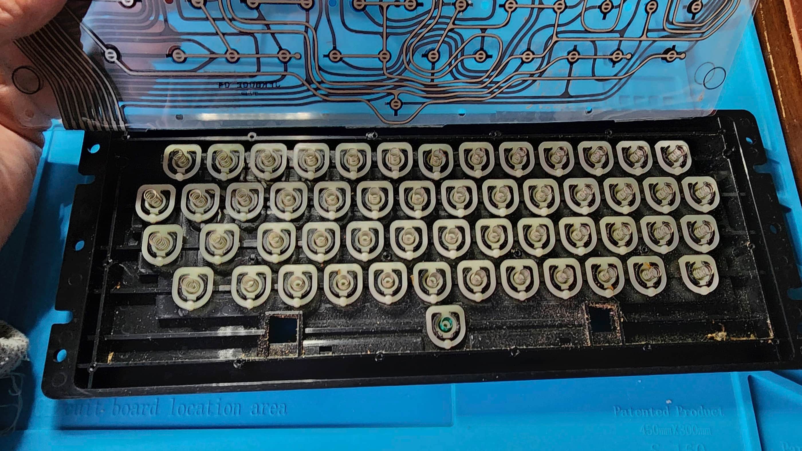
I then turned my attention to the Futaba mechanical switches, giving them each a good squirt of Deoxit D5 followed by several dozen presses. Once the keyboard was back together, I tested it and though some of the non-working keys were back to operational, there were still two that gave me grief. To fix them, I ended up desoldering them from the PCB and then carefully prying them apart to expose the pins and the contacts. Noting how dirty the pins were, I gave them a good scrub with IPA and then put the switches back together and soldered them back onto the board. I then gave the keyboard another test and all of the keys worked perfectly.
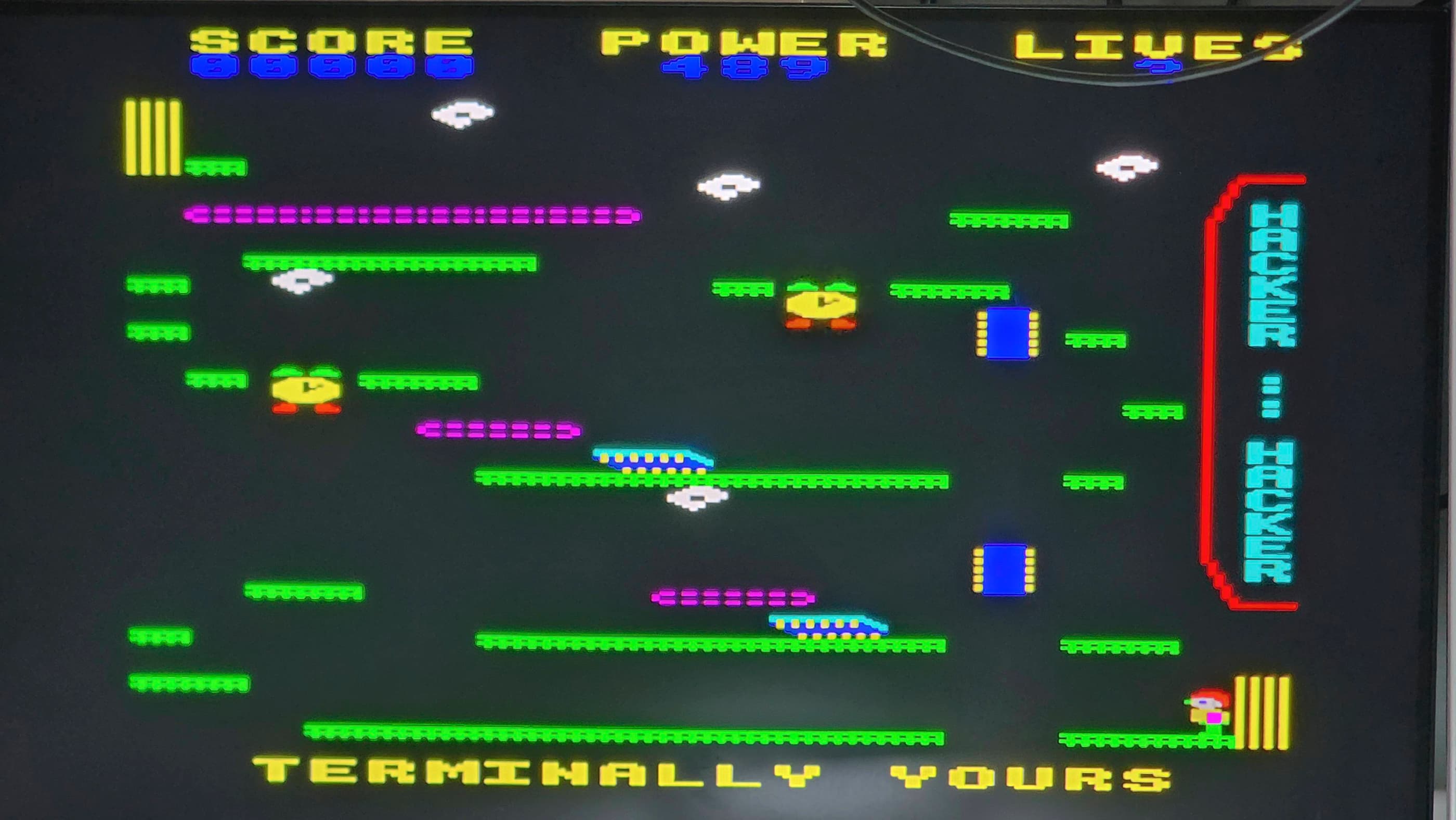
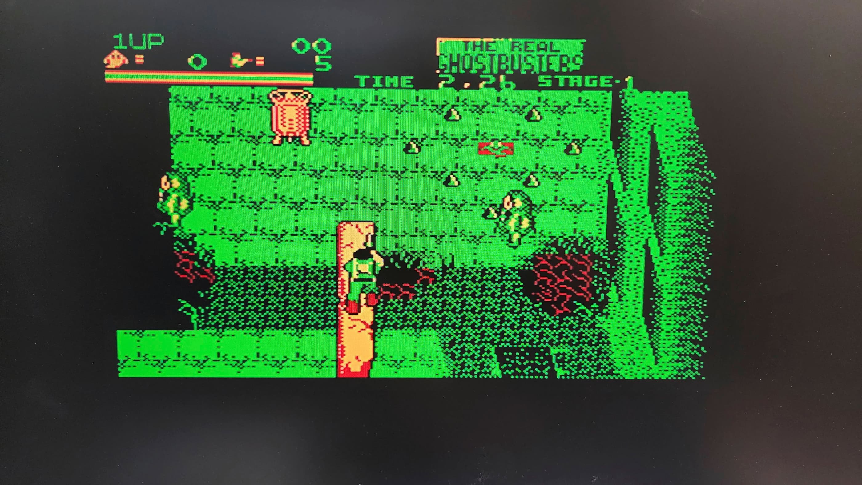
Finally, I tested the machine by loading several games including one called, Hacker, which would later prove to be a hit when the ‘Elk’ was displayed as part of my pop-up museum, “A Byte of History” at a local innovation event. Having the ‘Elk’ as a working demo meant it was on for several hours at a time and this proved to be great for further testing. It passed with flying colours!
Parts & Products Used: 99% isopropyl alcohol; Chemical Guys Silk & Shine; Deoxit D5; SCART to HDMI Converter; aluminum heatsink; Retro Computer Shack Acorn RGB Cable and Acorn Cassette Cable; electrolytic capacitors (axial) – 16v 470 μF (1), 40v 3300μF (1) electrolytic capacitors (radial) – 16v 47μF (1); 16v 1000μF (1) 25v 22μF (1); 50 v 10μF (1 – this was originally an axial cap, but I used a radial in its place); Dawn Platinum Powerwash.
Amstrad CPC 464
Years (1984-1993[?])
Interesting Fact: Rising from a young entrepreneur who sold imported car antennas from the back of his van to pioneering a ground-breaking audio amplifier at his London factory, Alan Michael Sugar was the innovative founder of A.M. S. Trading Company which he later shortened to Amstrad. (source) According to Sugar, in 1984 the company made the decision to diversify and enter the home computer market. (source)
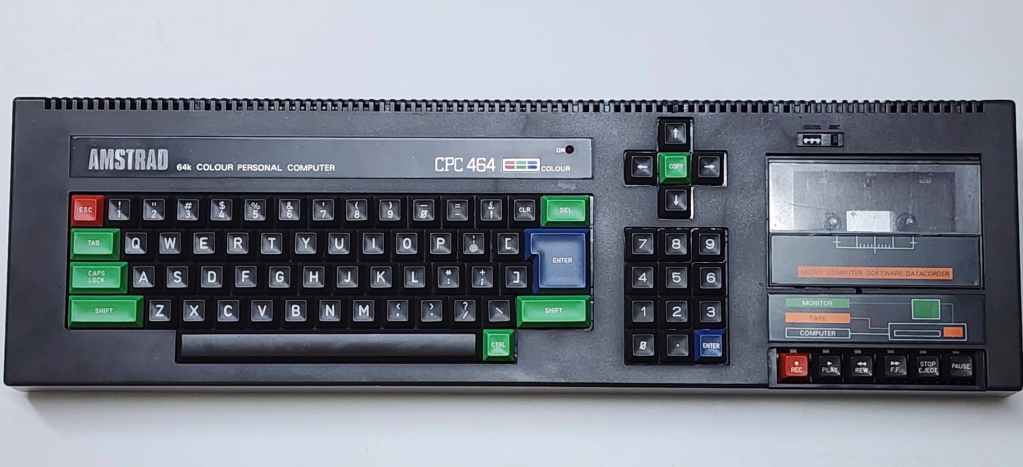
Though crowded with established competitors such as Commodore, Atari, Sinclair, and Acorn, Sugar saw a gap in the market. He stated that, “My concept was simple: Mum and Dad don’t want little Johnny taking over the TV set, so our computer should come with its own monitor, have a full-sized keyboard and a built-in cassette mechanism for loading software and hit a target price of £199. This way, little Johnny could have it in his bedroom, freeing up the family TV. A great concept.” (source)
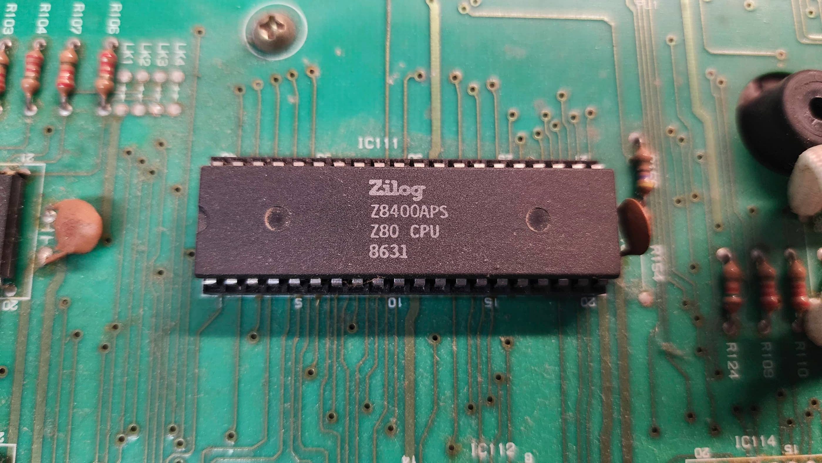
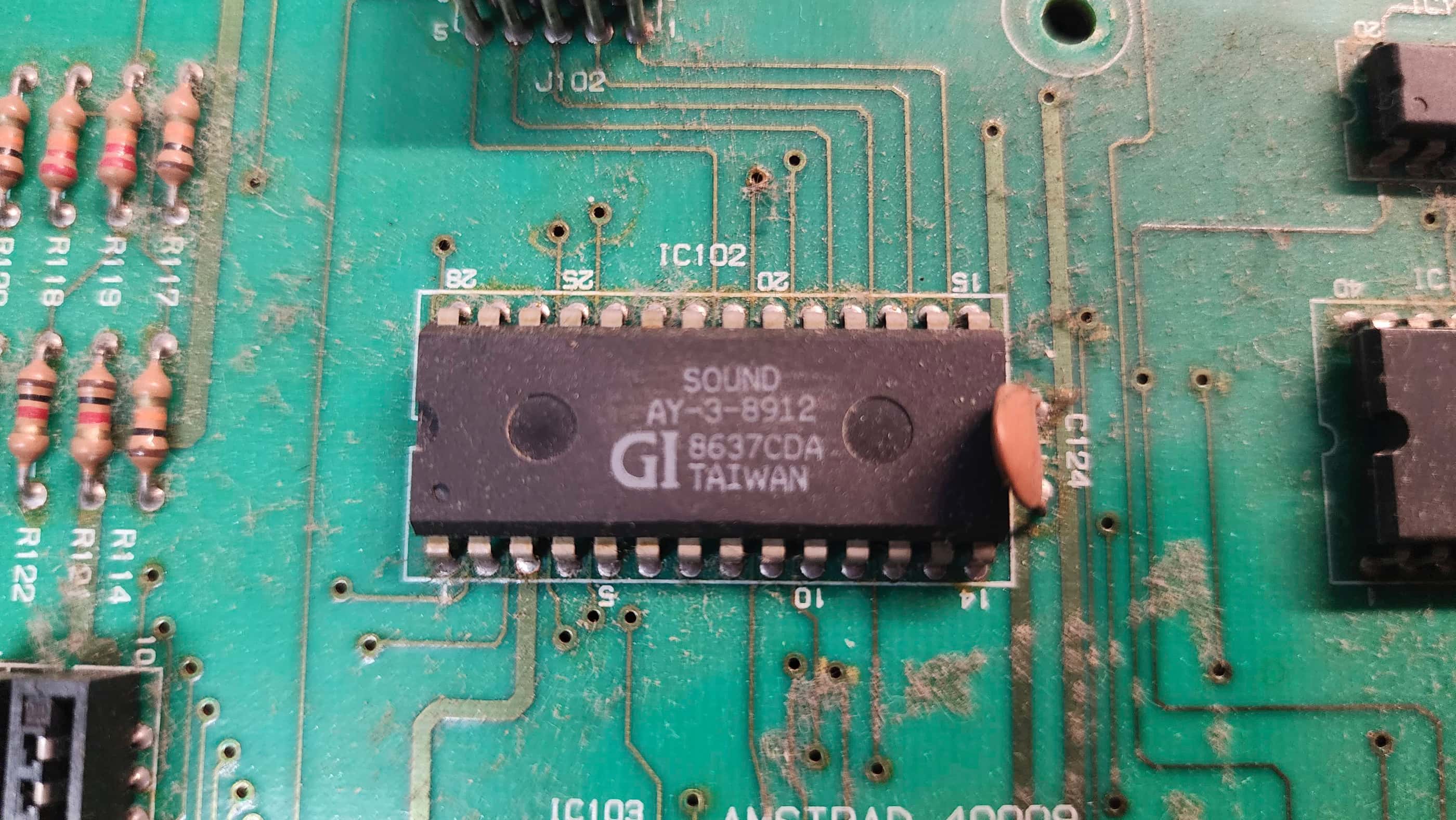
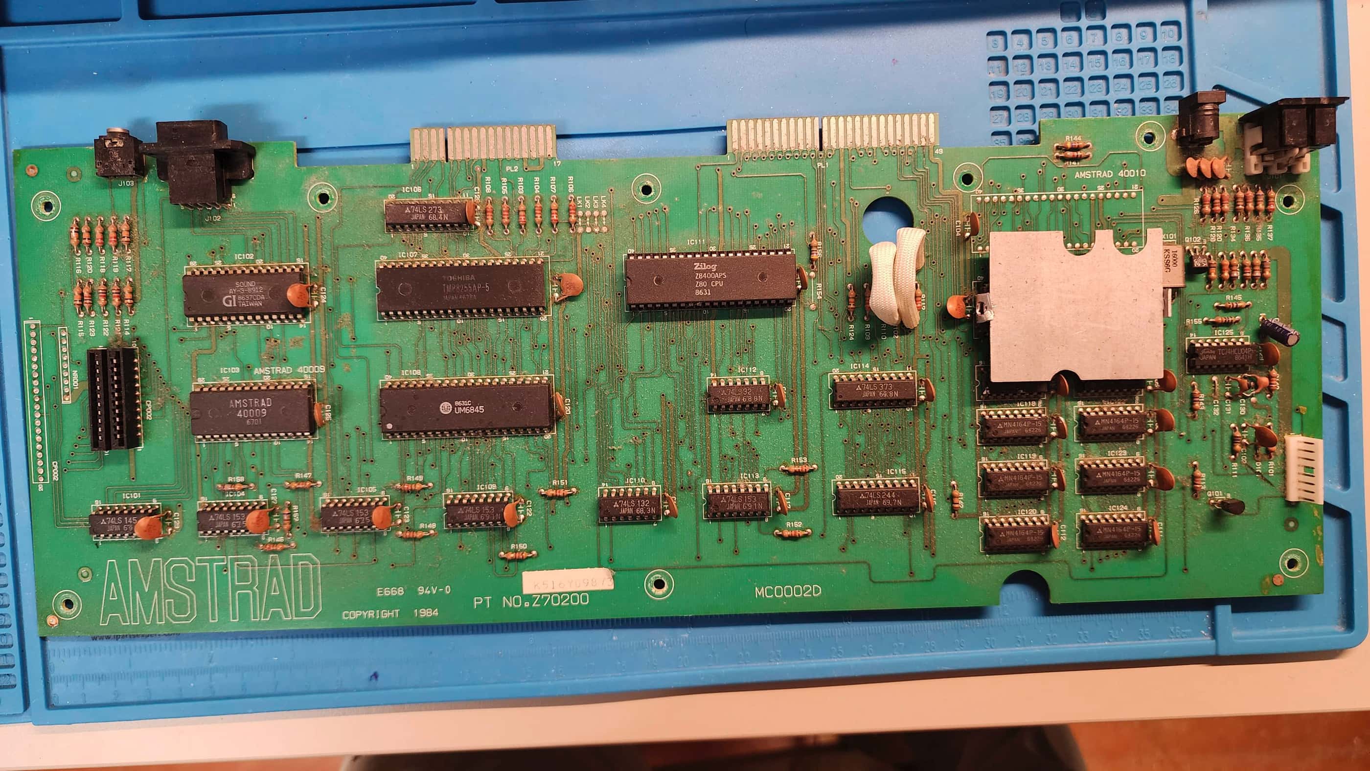
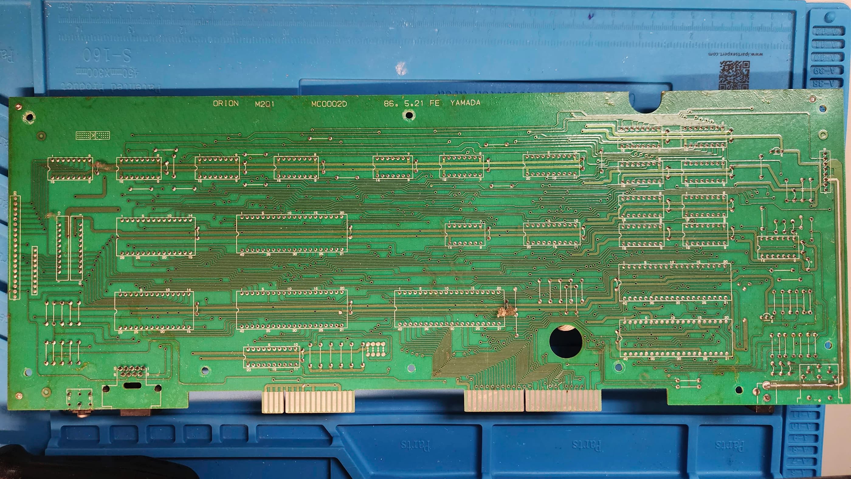
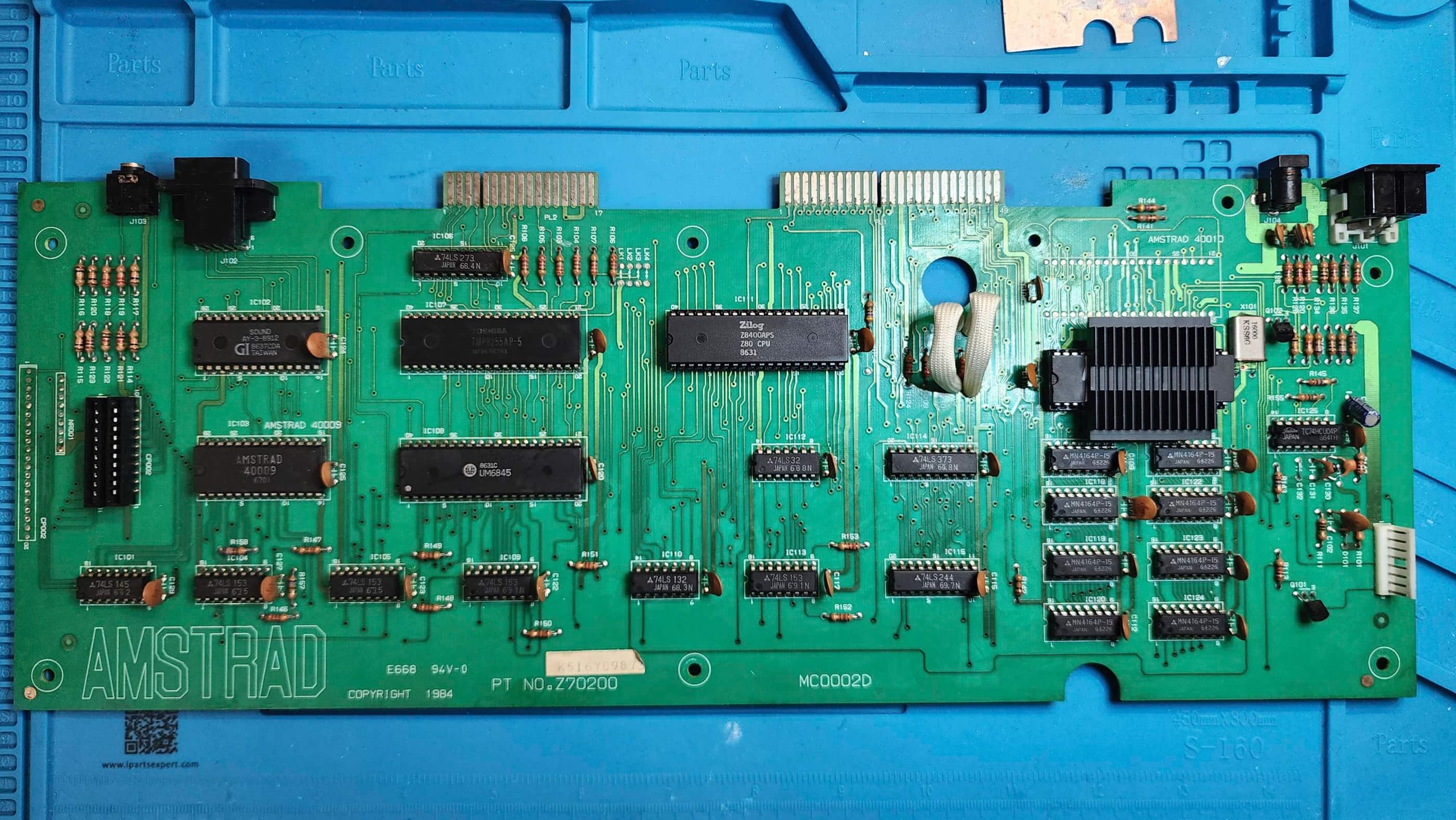
The result was the Amstrad CPC (Colour Personal Computer) 464. Using a 4MHz Zilog Z80A as the CPU, a custom Amstrad Gate Array chip, a 32K ROM chip (which combined two 16K ROM chips – one of which contained the custom AMSDOS Operating System), 64K of RAM, a standard AY-3-8912 sound chip, and a built-in tape drive, the CPC464 rocketed onto the market. (source) Each computer came with either a colour or green screen monitor that also doubled as the power supply for the computer. (source) Moreover, the CPC464 also included the ability for 80 columns that made it favourable to small business users. In total, the CPC464 would sell millions of units in Europe.
Condition When Acquired: Fully Functional
Current Condition: Fully Functional

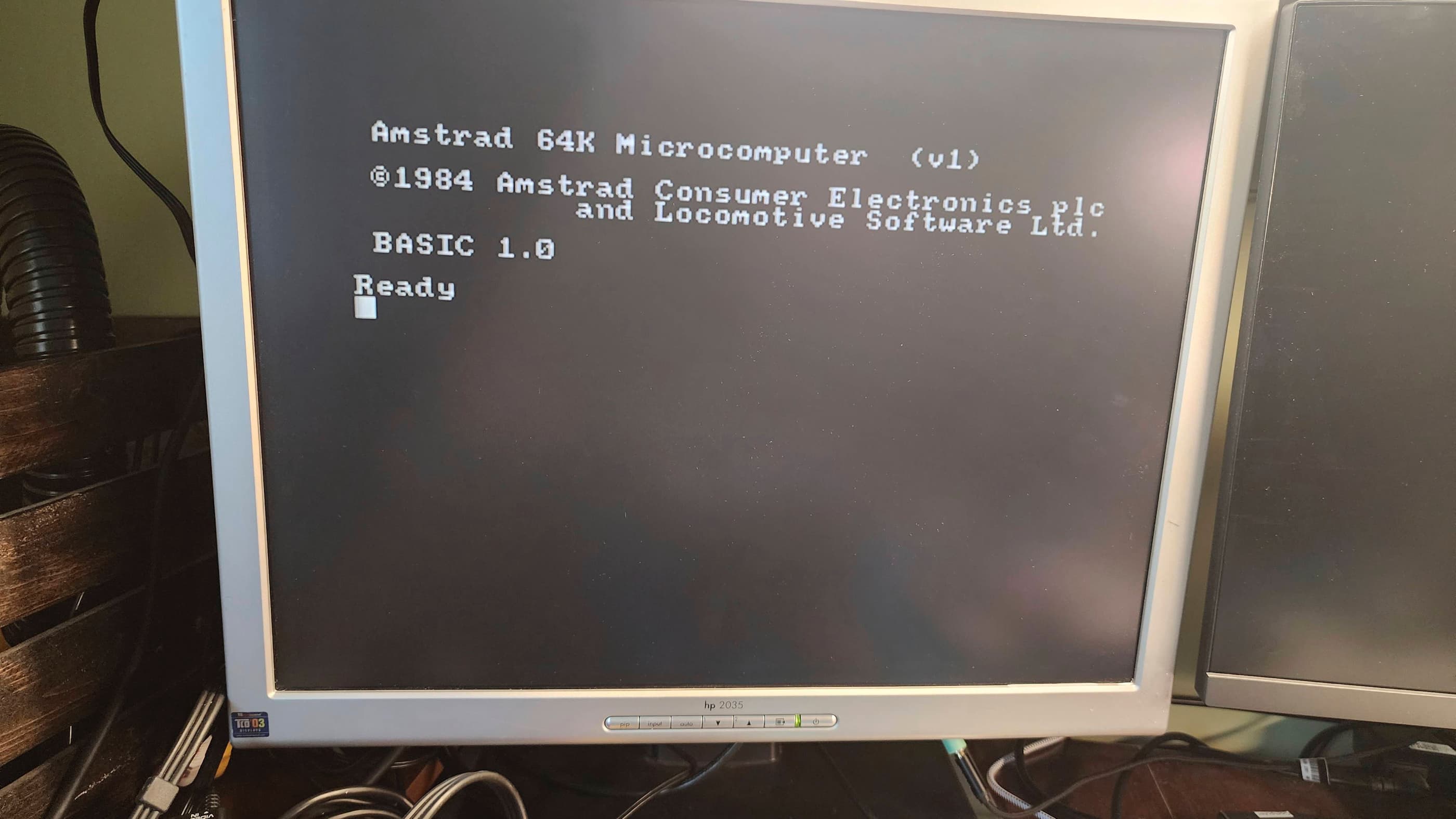


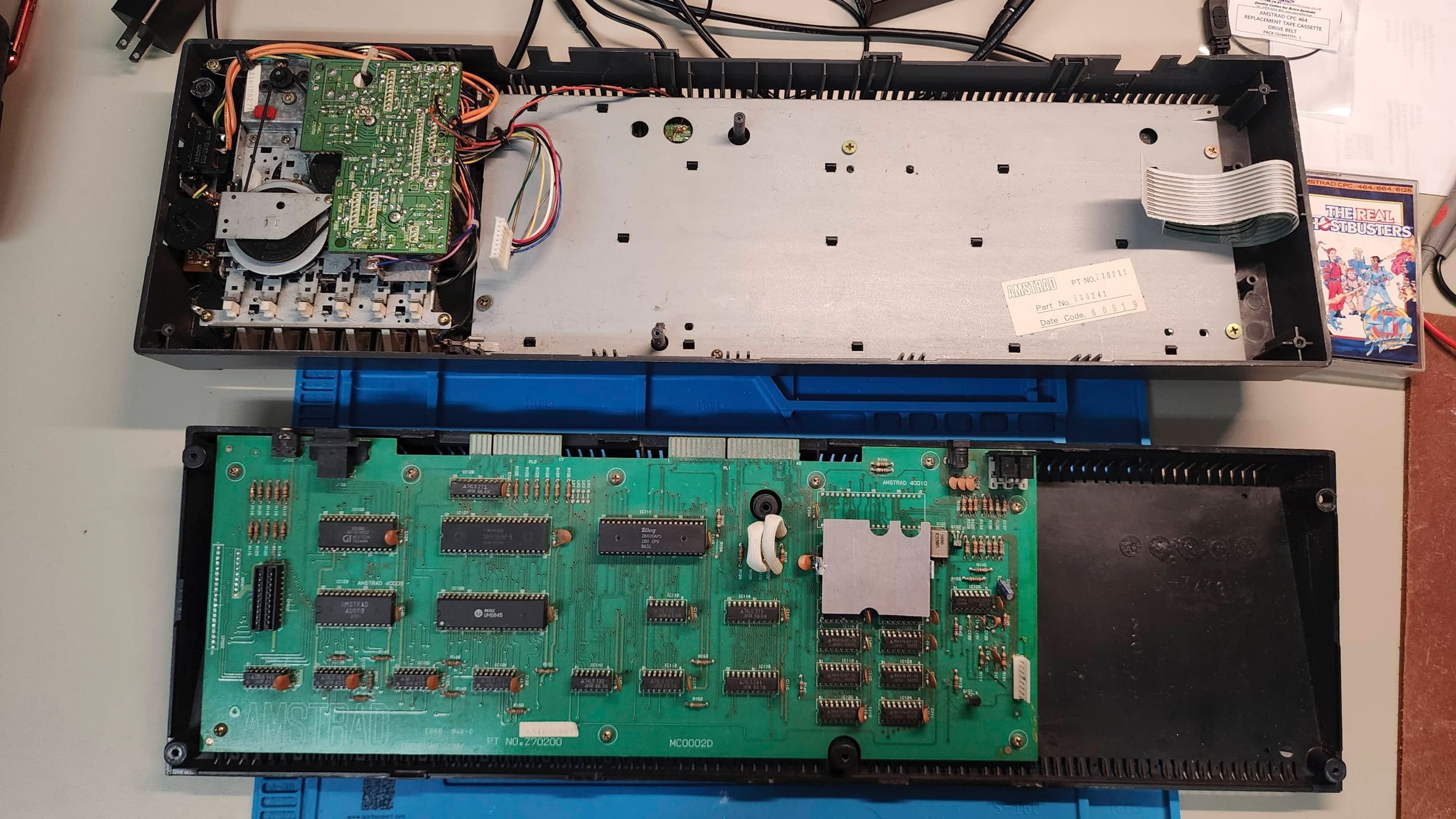


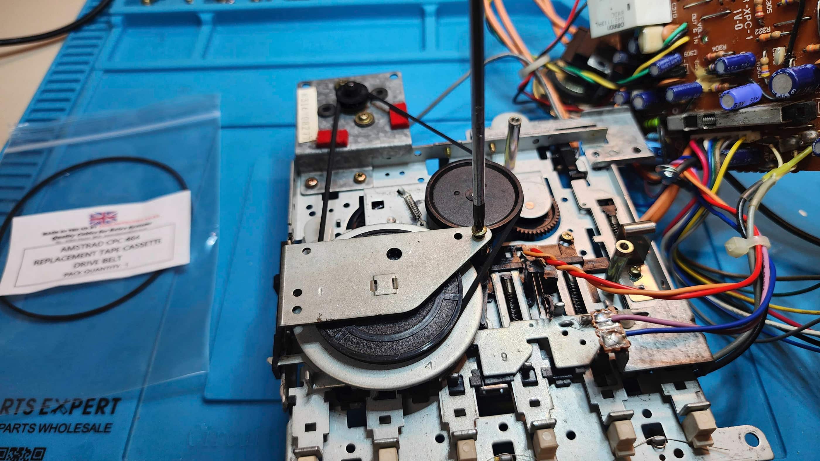
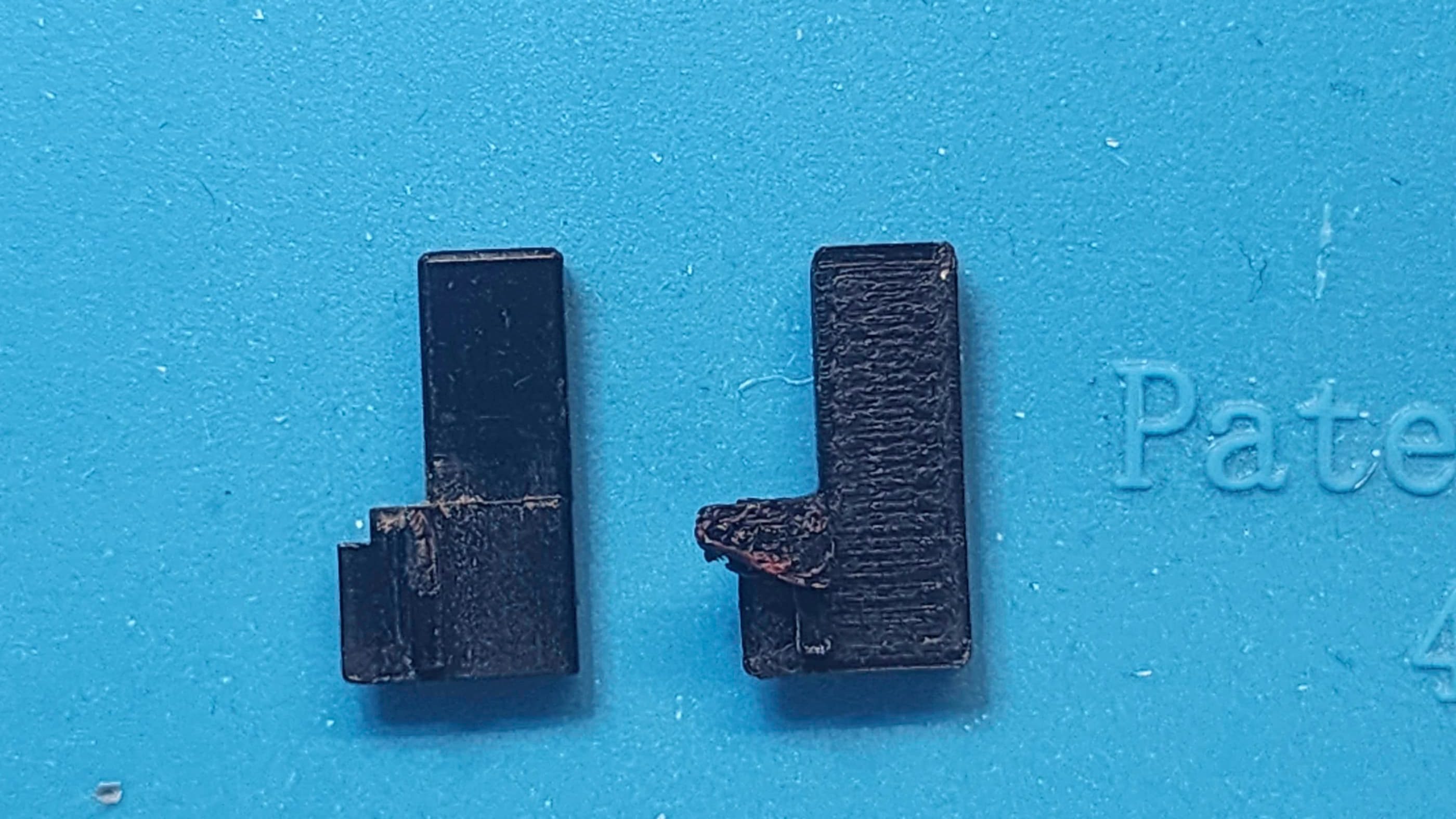
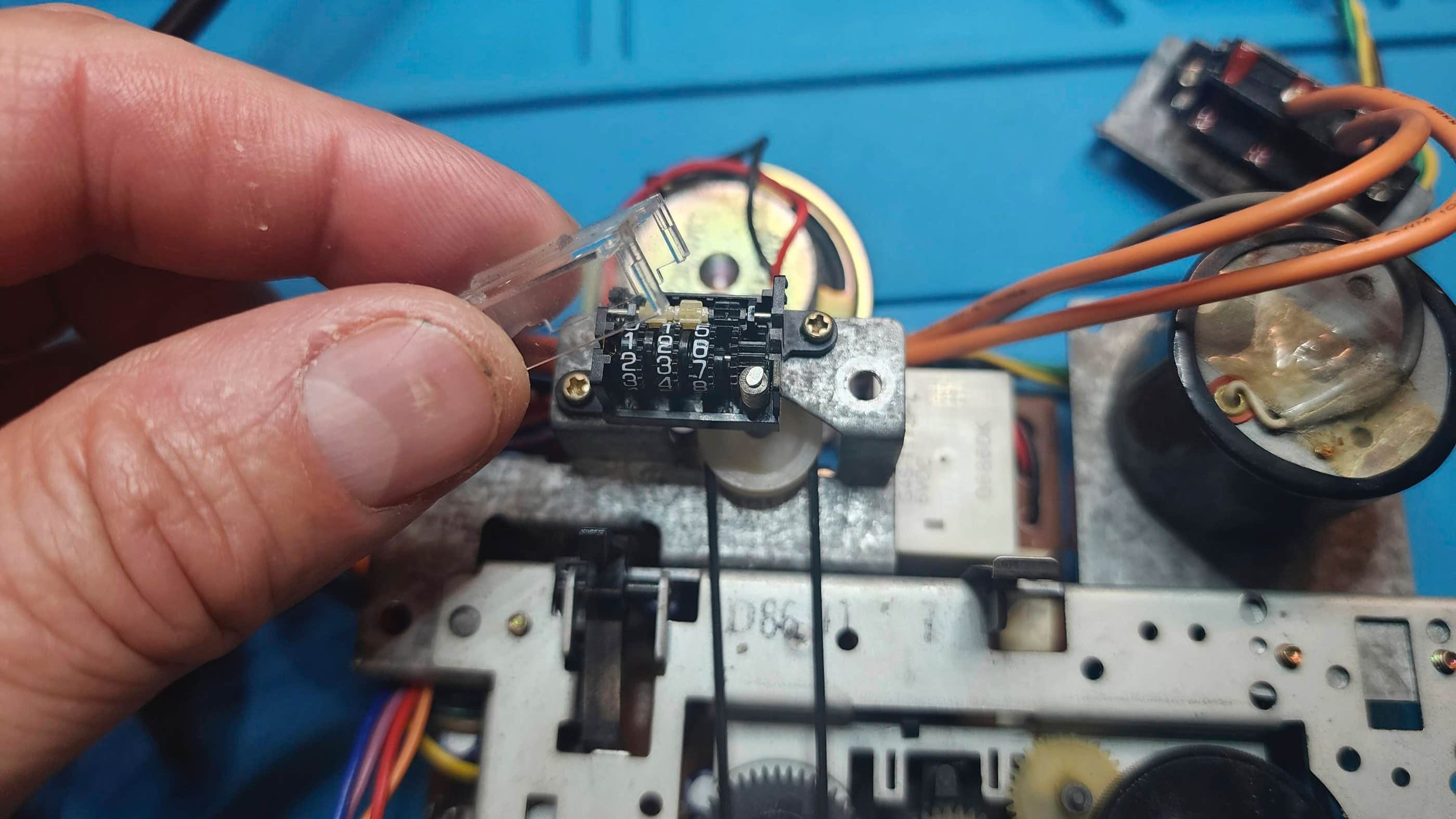
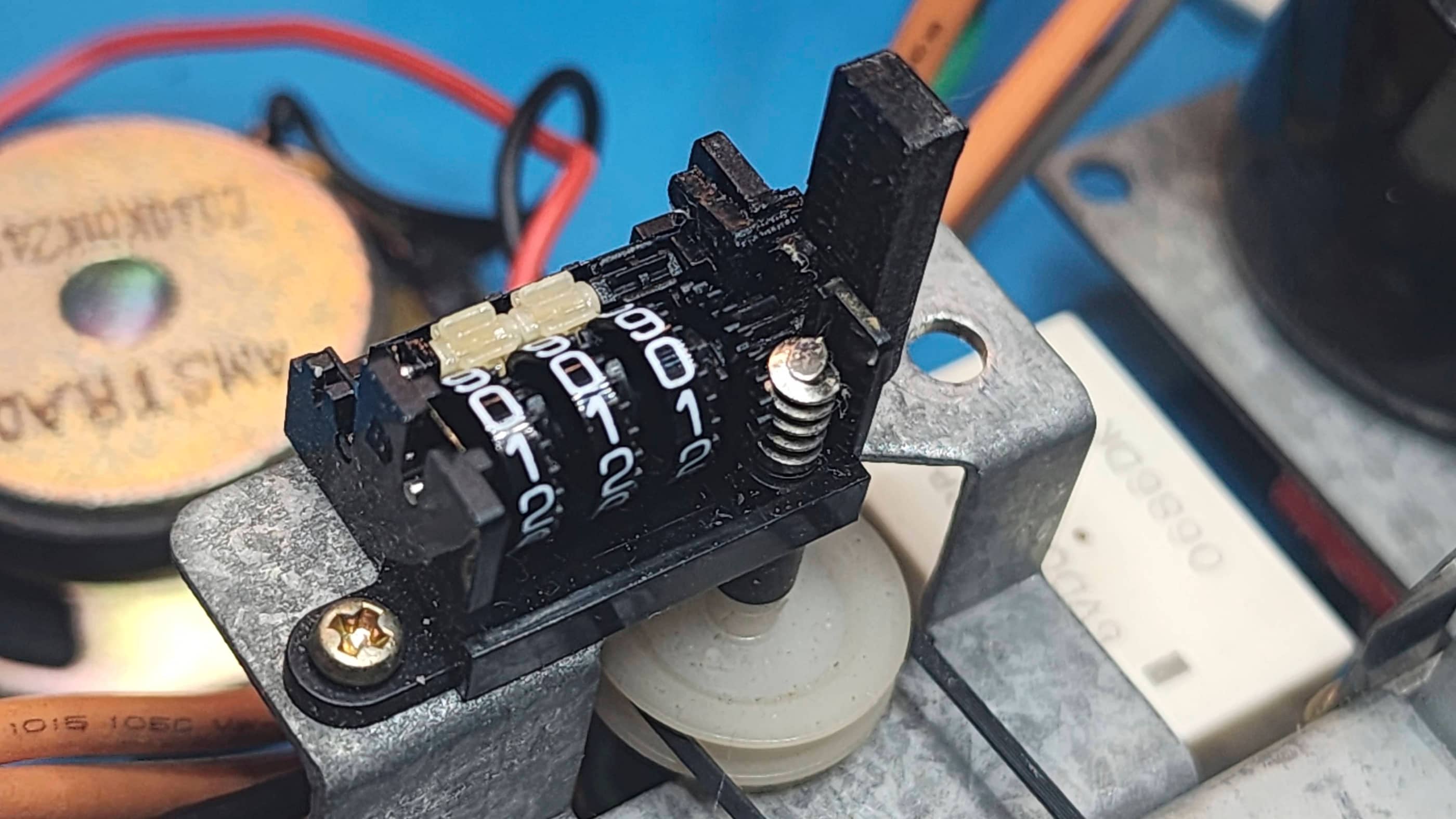


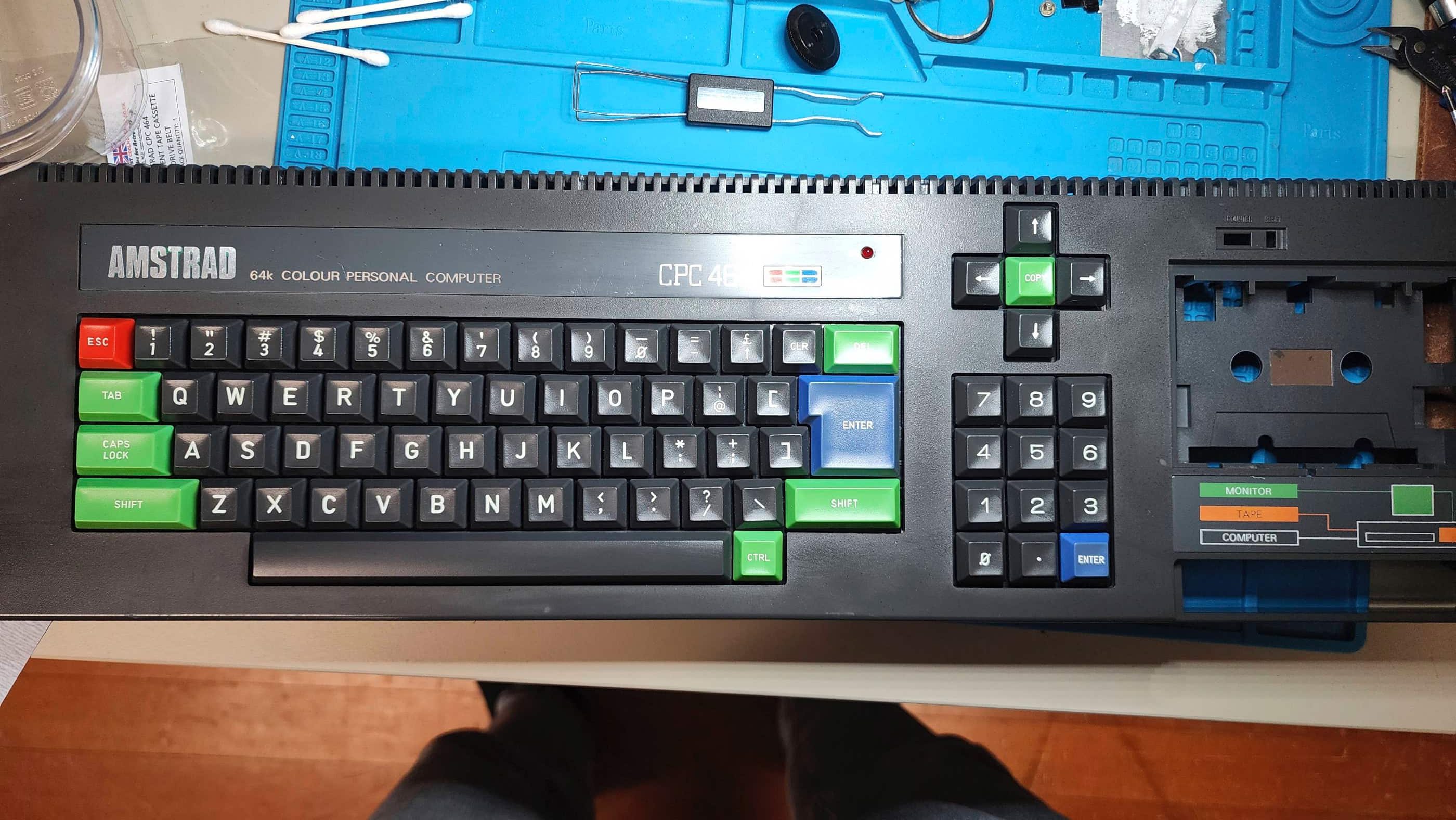

Project Details: I was super excited to receive my first British computer that surprisingly, came from a Canadian eBay seller. I knew from the seller (who I have purchased from before), that the unit turned on and that the tape drive worked; however, the seller did not have the proper cable to see anything but a B&W display. The counter reset button on the tape drive was also broken which is the most common problem for Amstrad CPC464s.
As the seller lives close to me, I received the computer lickity-split, but before starting the project, I wanted to make sure that I had the proper video cable to display colour. As the CPC464 came with a monitor that also served as the power supply, I discovered that a cable would need to include the 5V power. Fortunately, an eBay seller in Greece (Retroworkbench) manufactures the required SCART cable and after receiving the cable, I can vouch for its quality. In addition to the SCART cable, I also need to purchase a SCART to HDMI converter which I found on Amazon. For good measure, I also ordered in a new tape drive belt from eBay seller, CoolNovelties, in the UK.
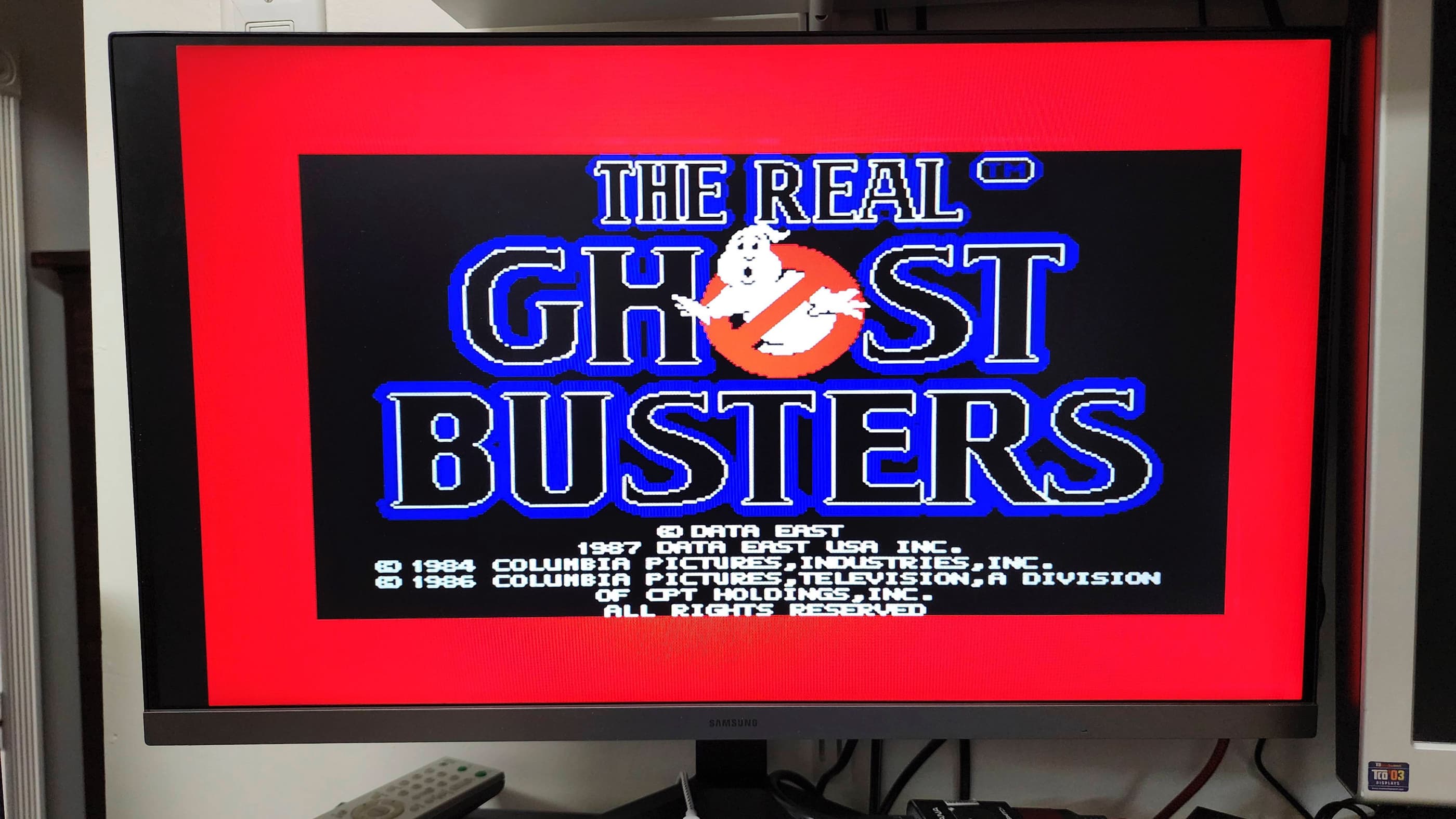
Since I did not have any software to run, I found a set of CPC464 cassette games from another UK eBay seller, that I acquired for a good price. As I was in the middle of packing up my electronics workshop to prepare for moving, I wasn’t able to begin work on this project for several months which was good, since it gave me a chance to have everything ready to go once I setup my new workshop.
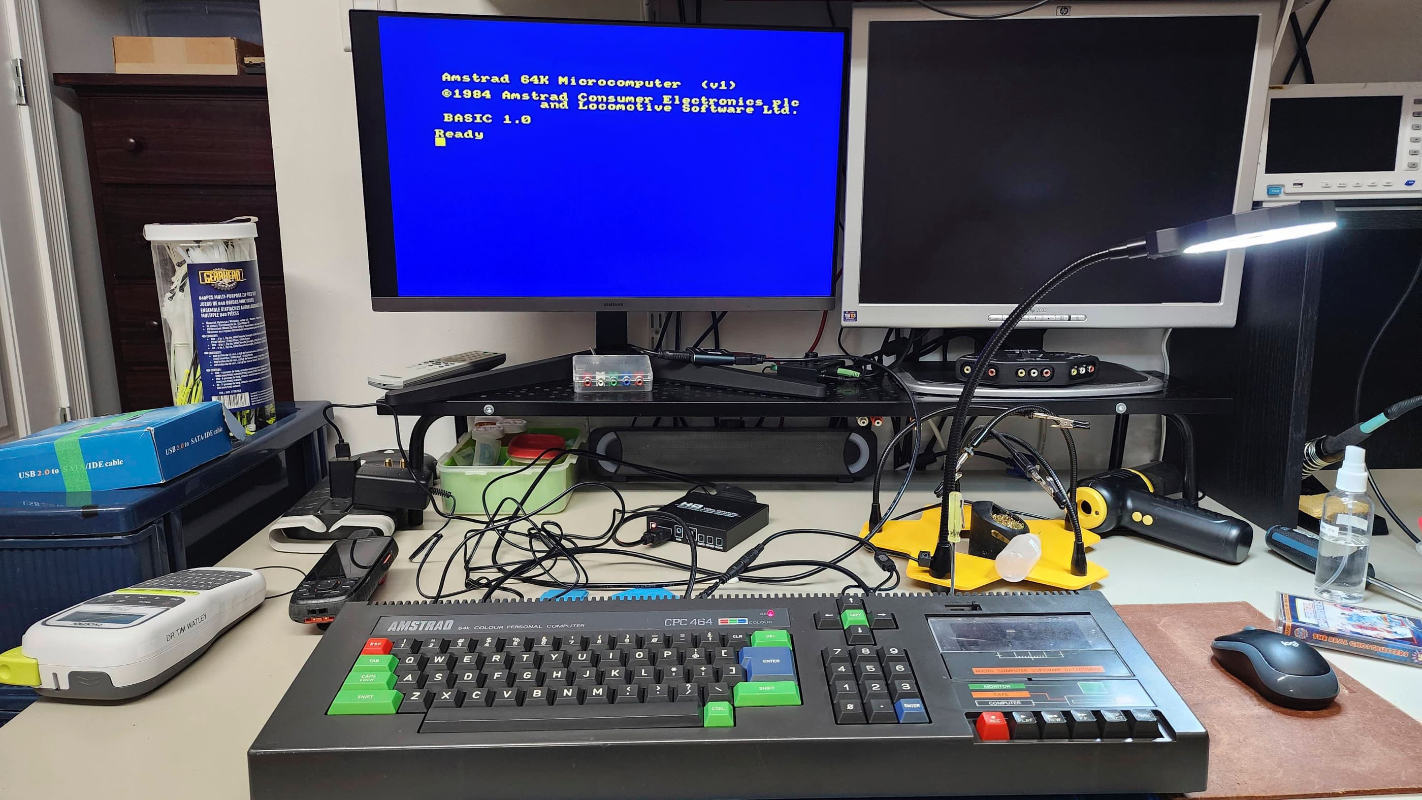
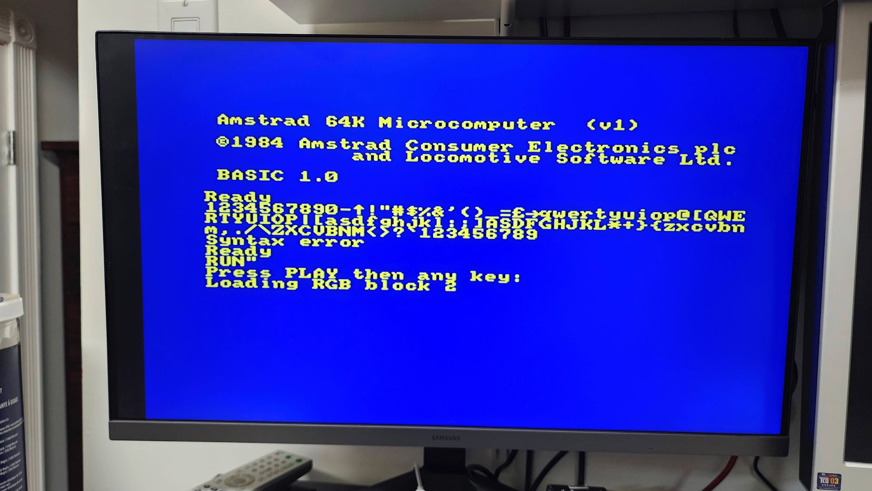
Powering on the computer, I was pleased to see that not only did the display work, but the tape drive had no trouble loading a game. The keyboard also functioned perfectly. This was great news and a great project to christen my new workshop with!
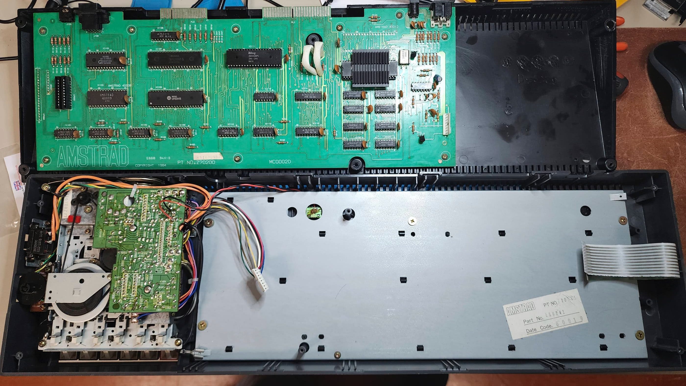
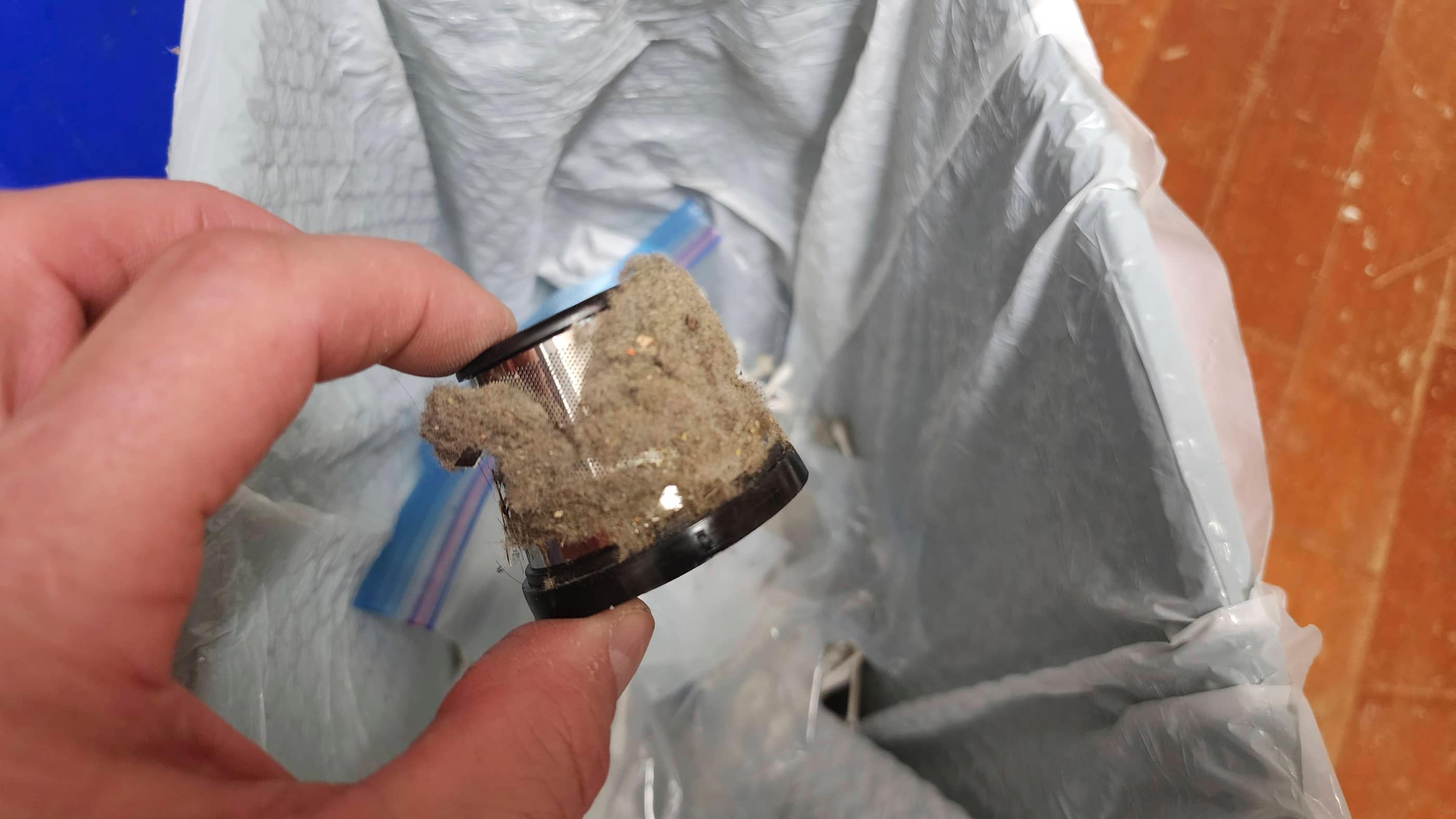
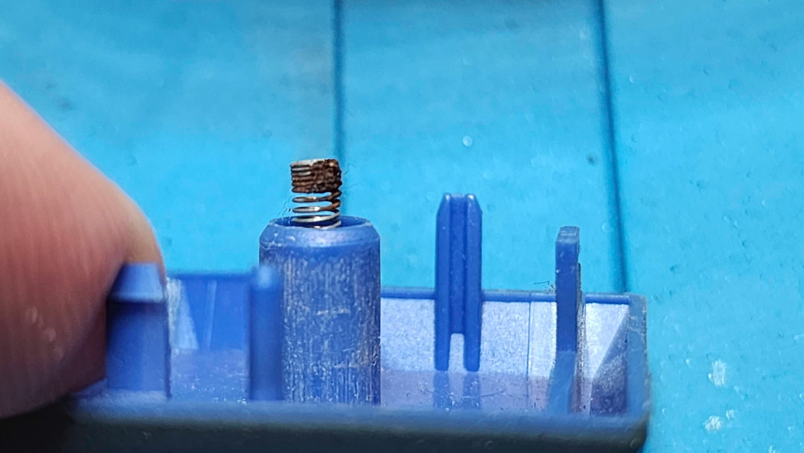
On opening the computer, I could see that it was extremely dirty. Wherever it was stored, it was a very dusty location. At some point, someone had also spilled a sticky drink on the keyboard which made for a big mess and some rust key springs on the keyboard.
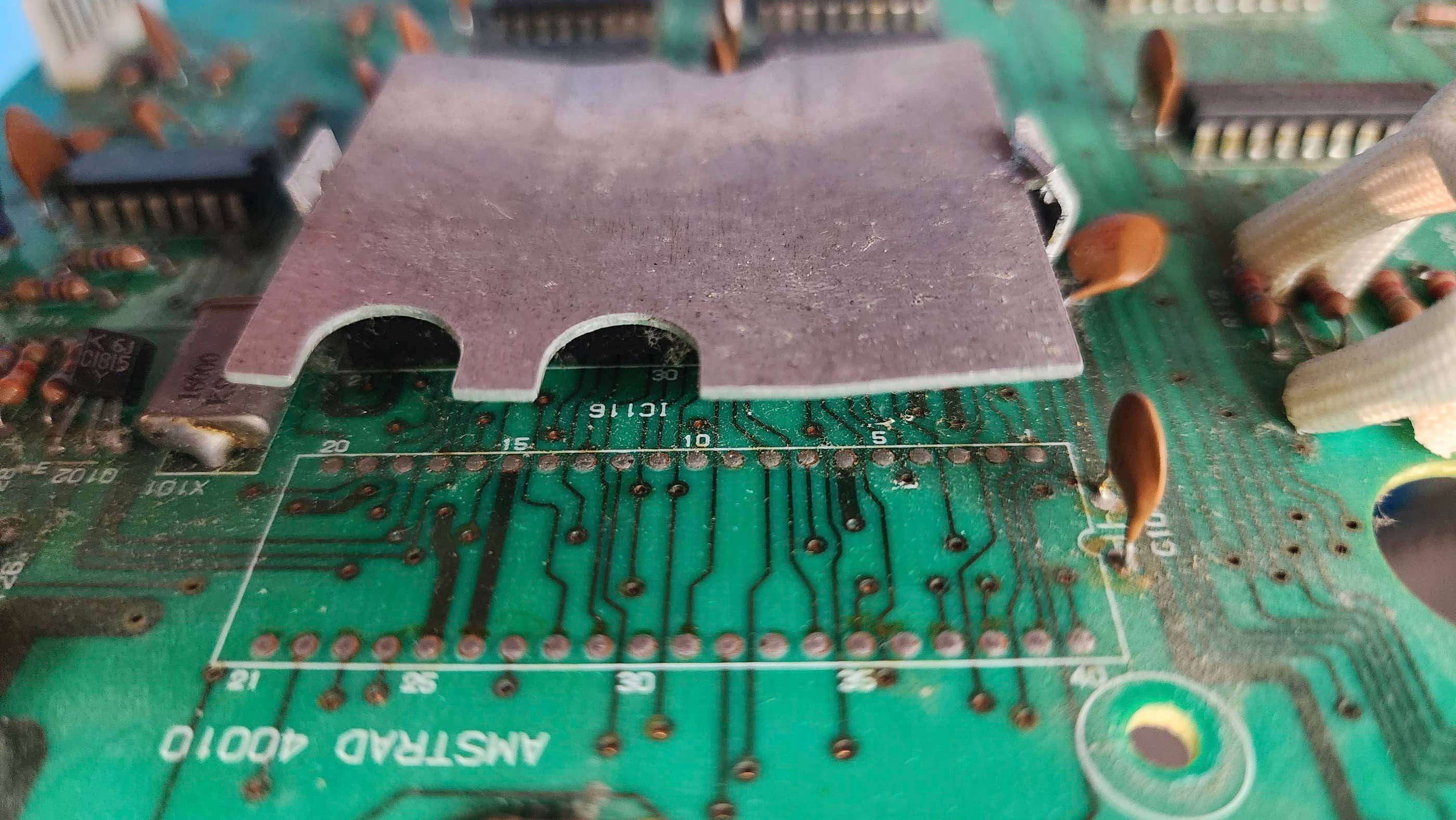
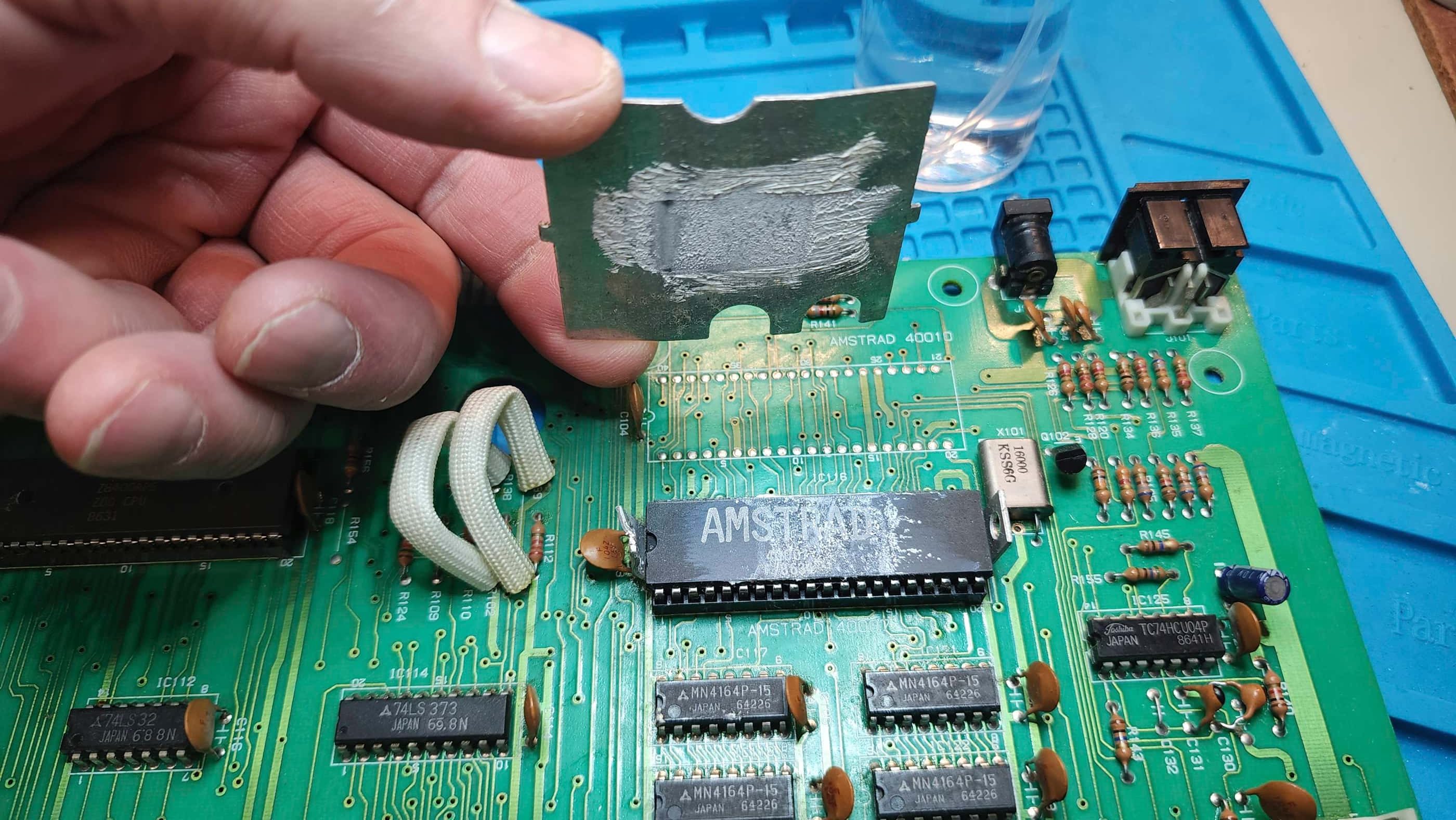
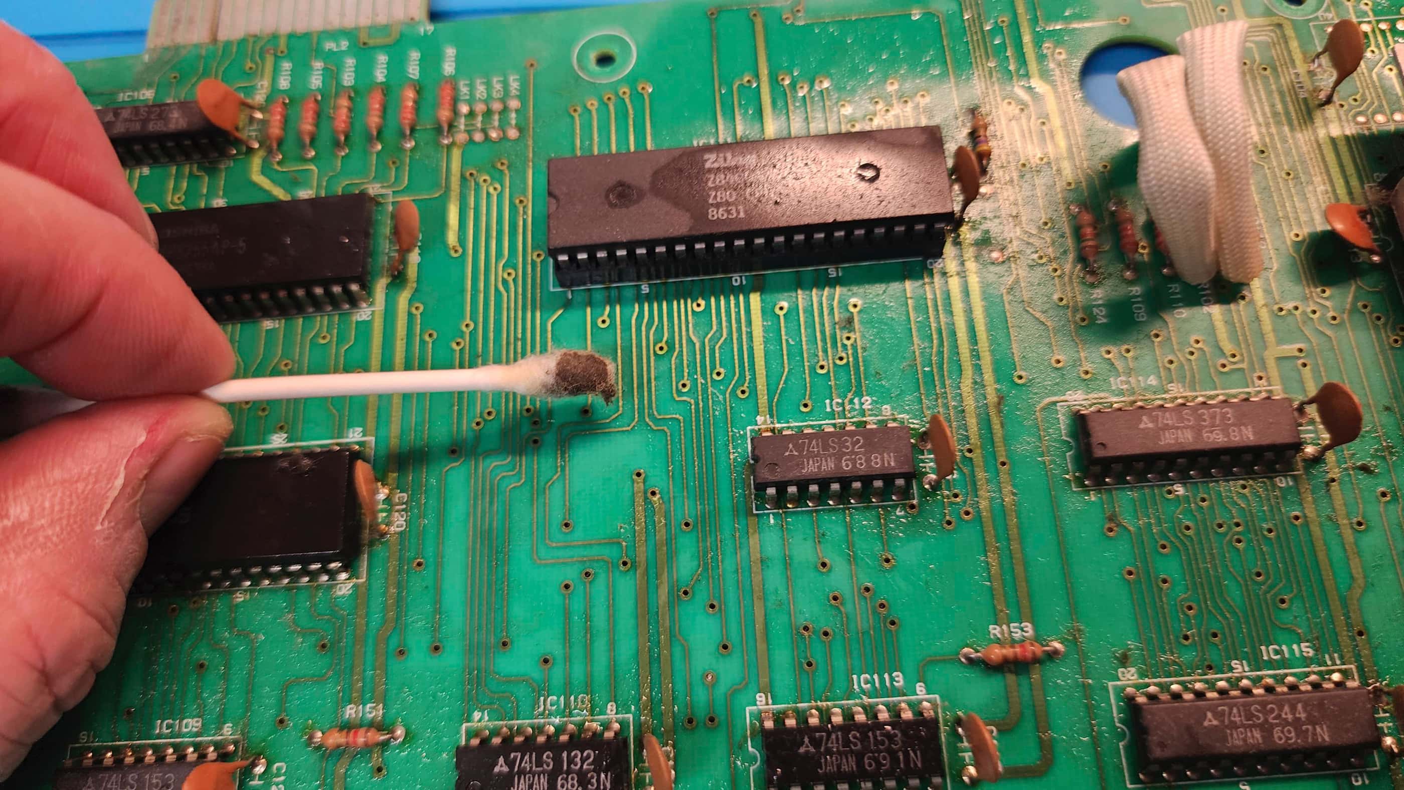
As I was new to the CPC464, I relied heavily on the excellent repair series from Noel’s Retro Lab. Thanks Noel! After cleaning the main board, I replaced the OEM heatsink on the custom Amstrad 40007 Gate Array chip with a more effective modern heatsink. I also reseated this chip and the CPU, treating both with Deoxit D5 in the process.
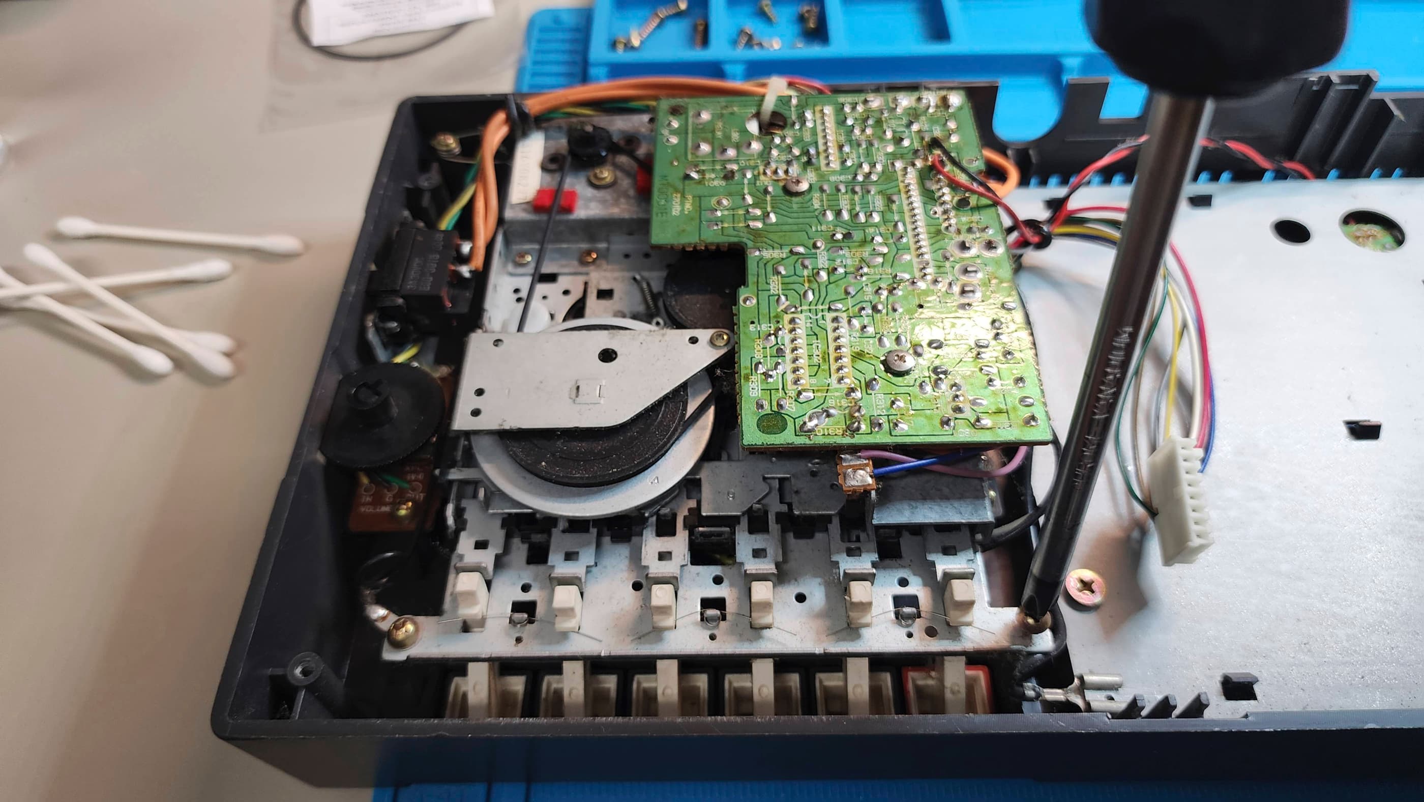
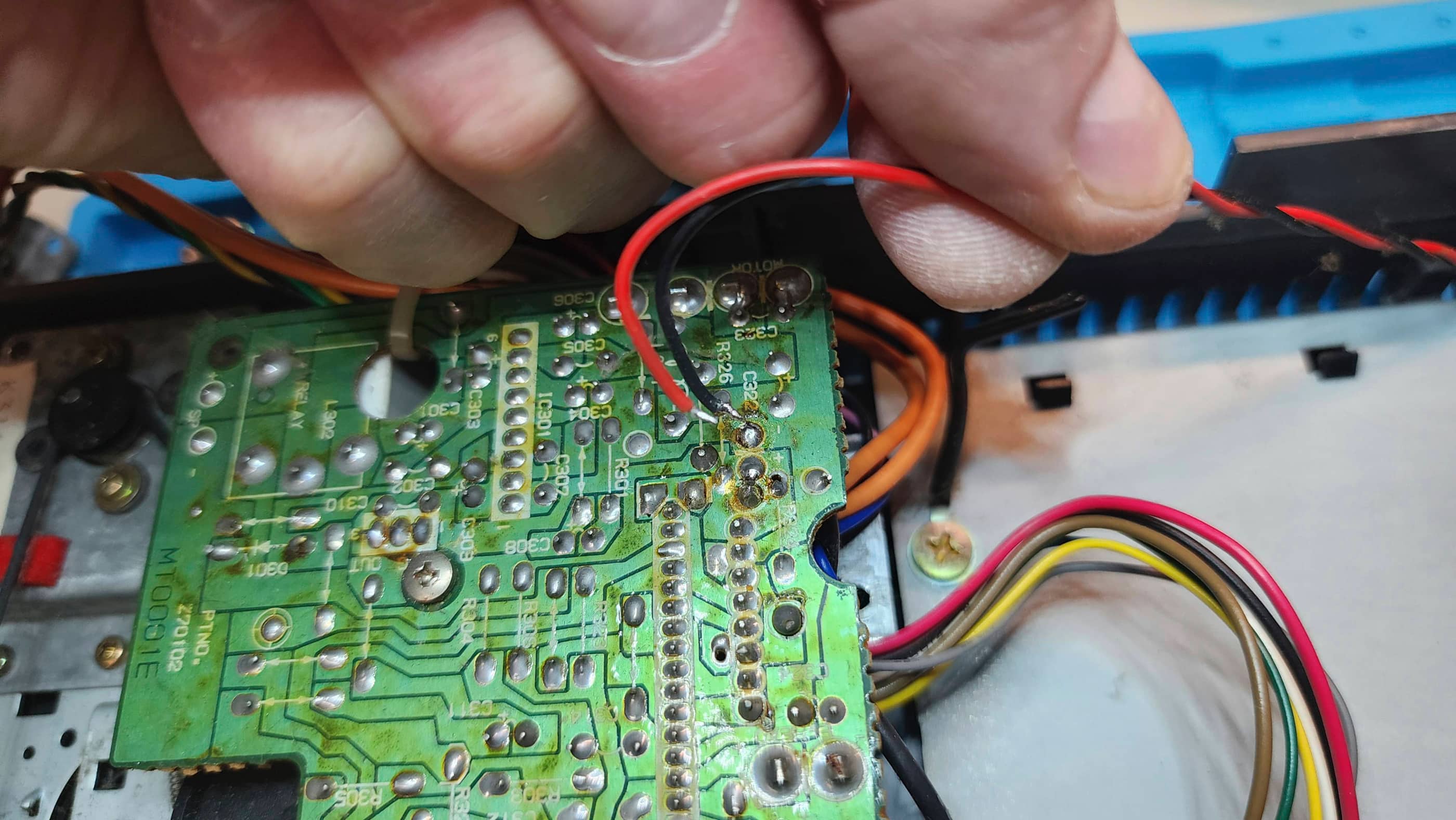
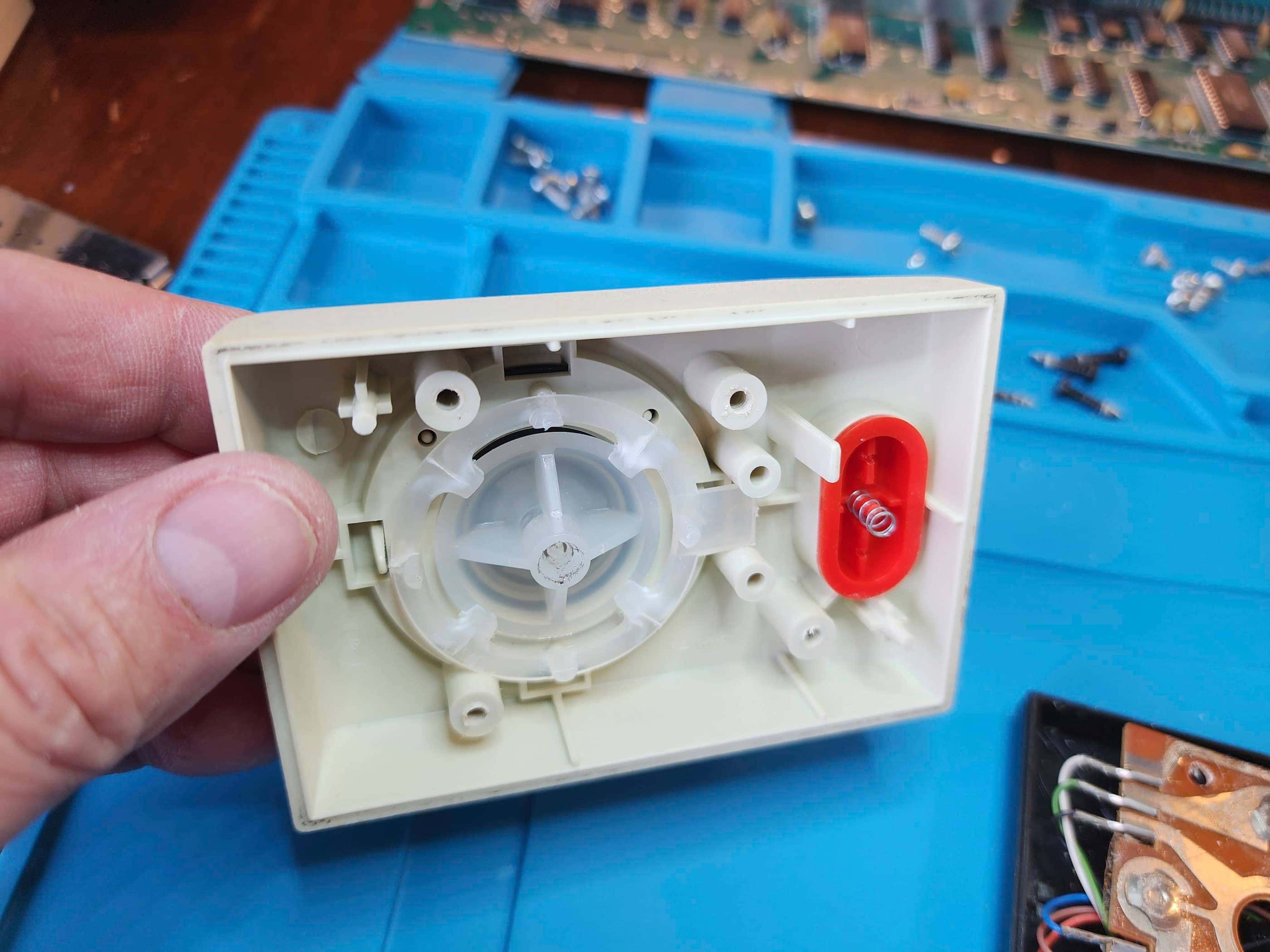
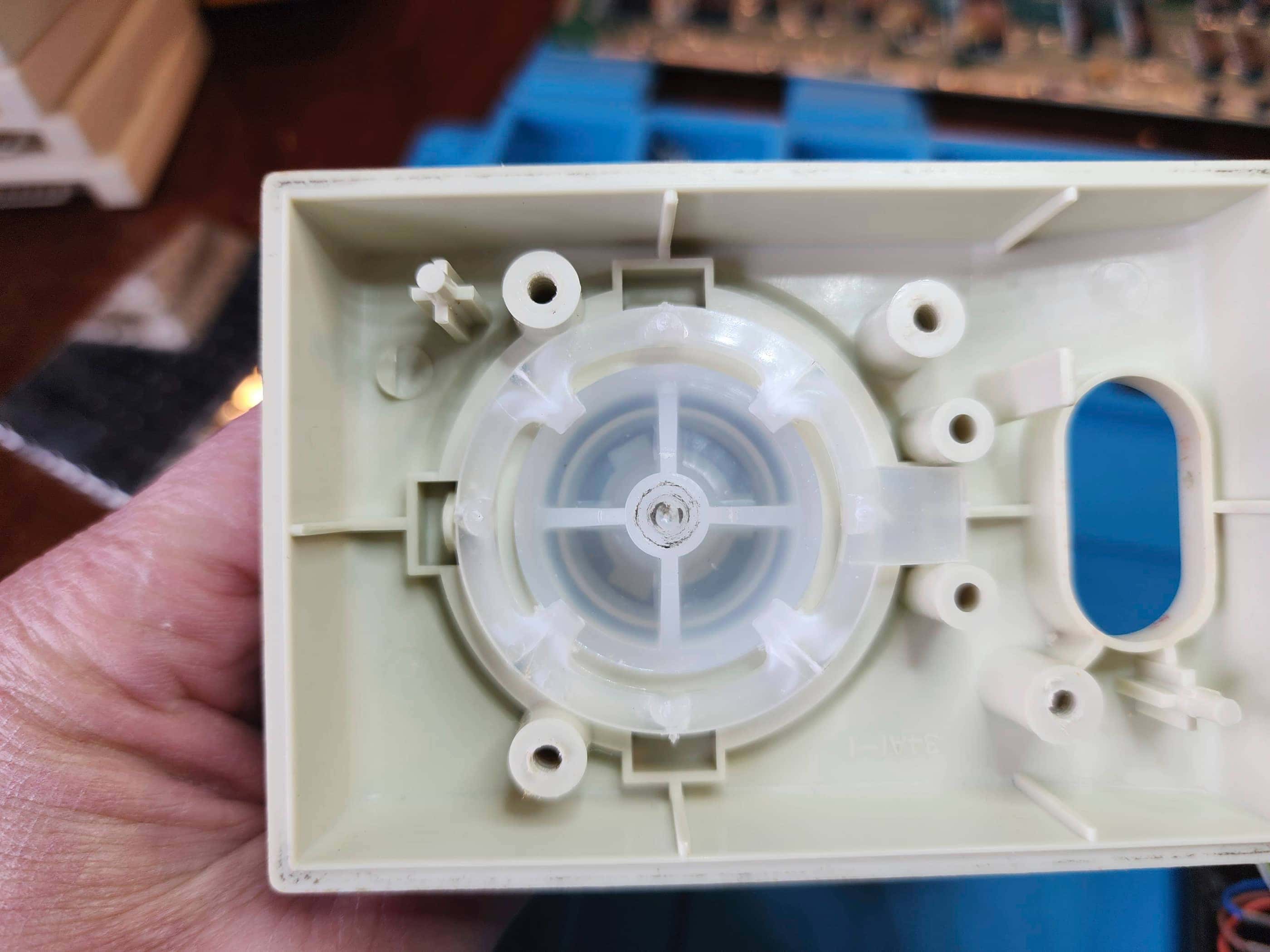
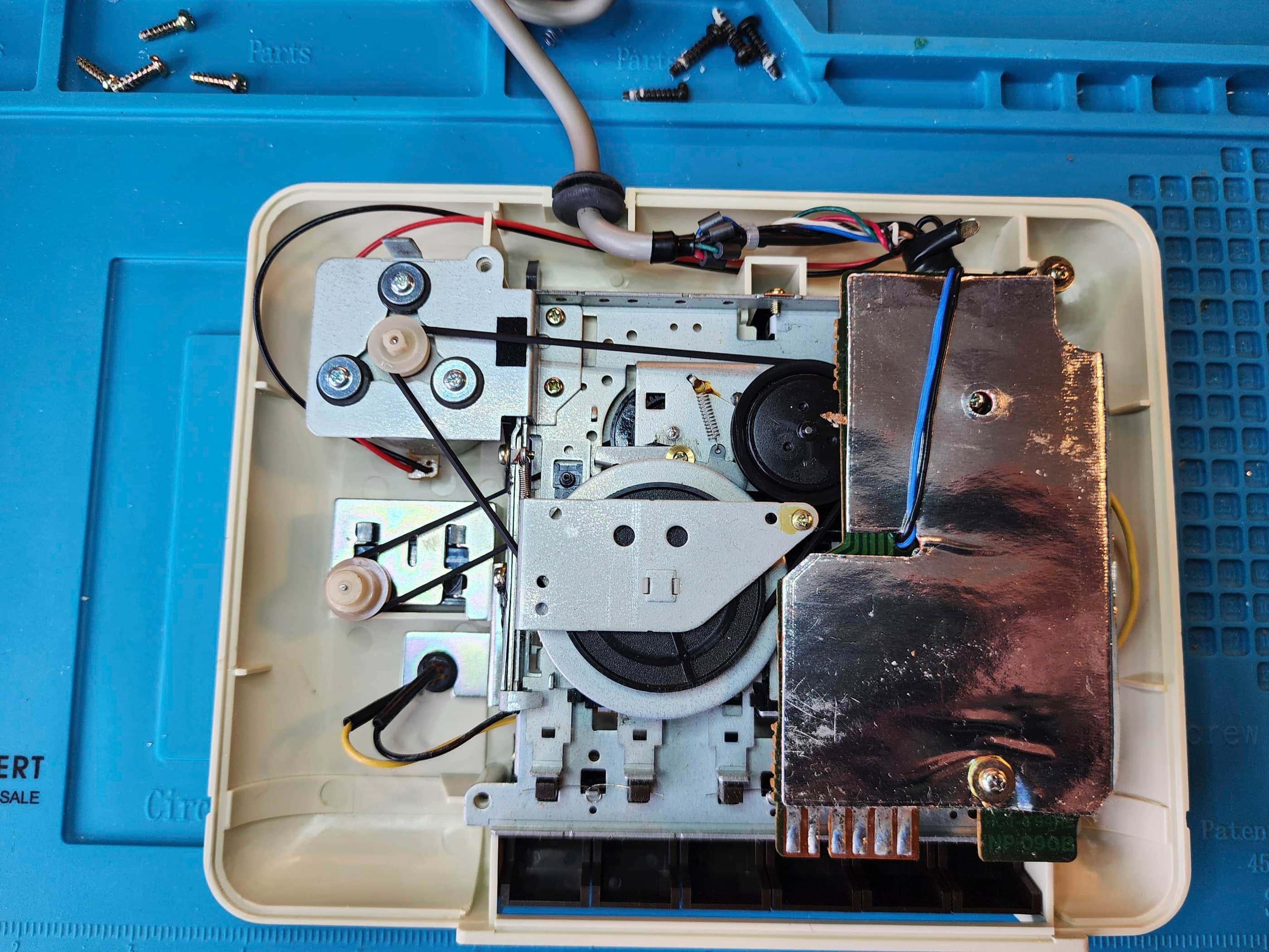
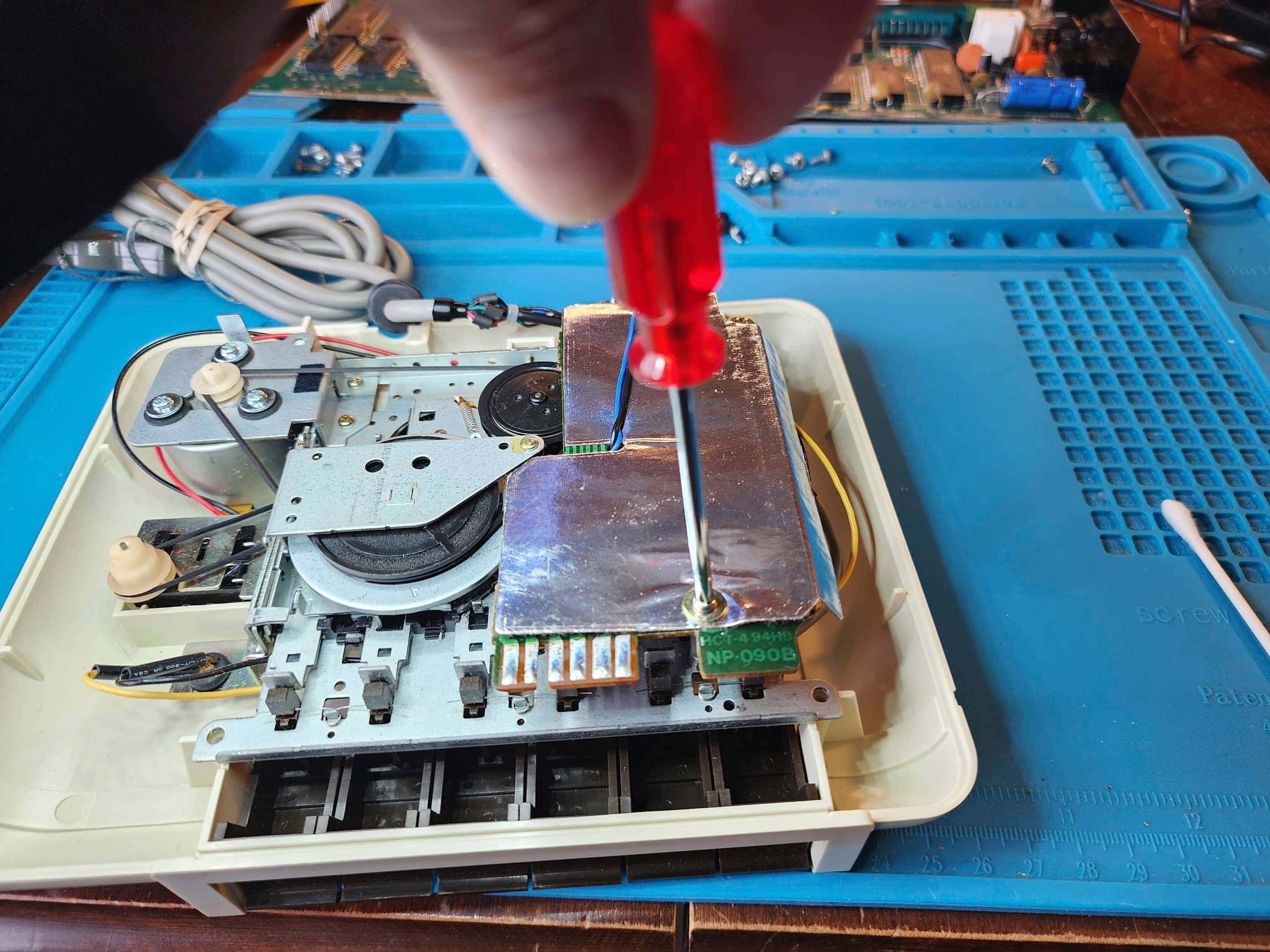
I then turned my attention to the tape drive, where I replaced the drive belt and cleaned the unit. I checked the capacitors and since all looked good, I decided to leave them alone. I downloaded an .STL file and 3D printed a replacement for the counter reset button. It fit well.
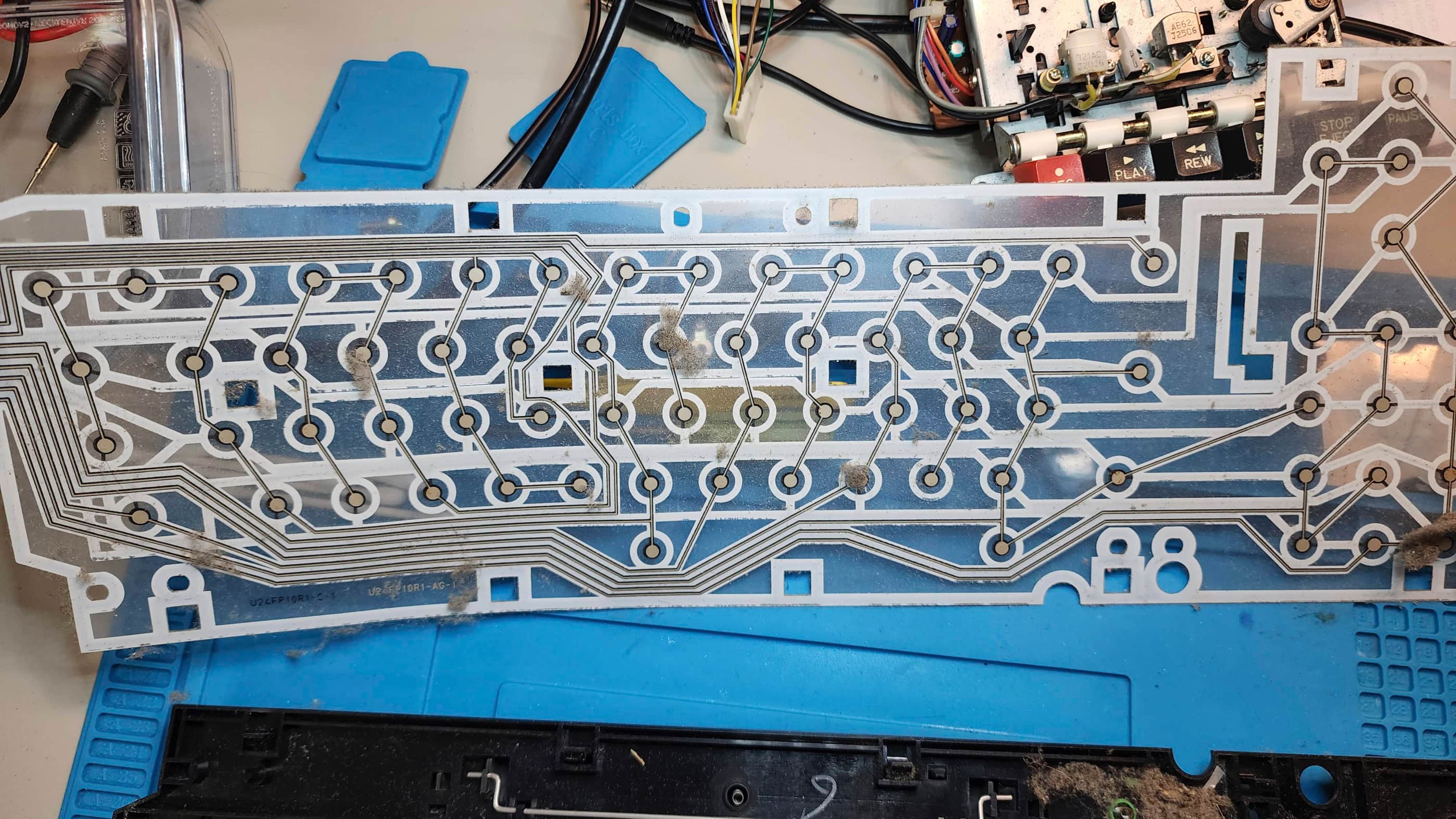
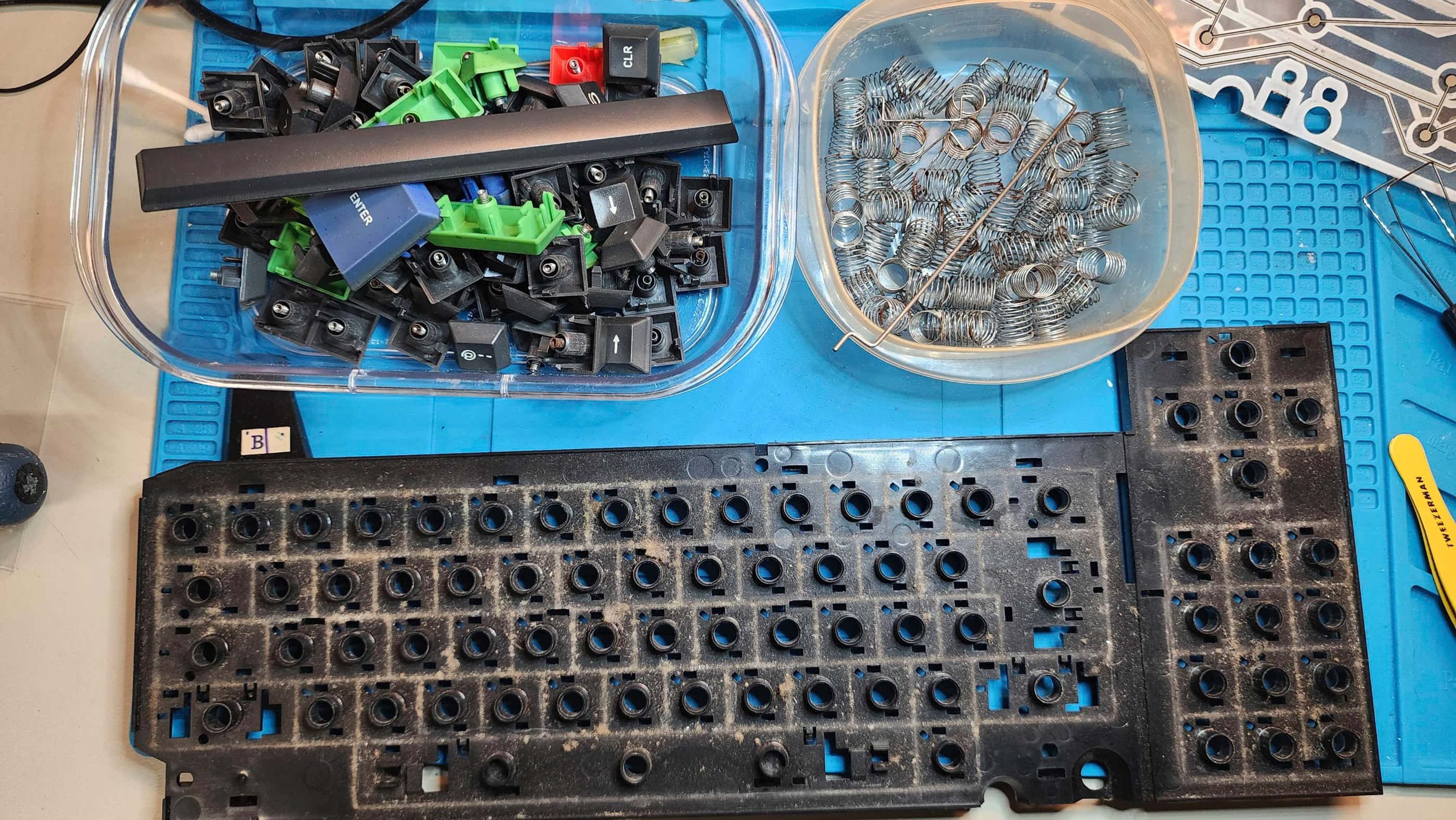
Once the tape drive was back together, I disassembled the keyboard, where I was greeted by a disgusting amount of dust and dirt. After cleaning, I gave the rusty key springs a soak in vinegar to clean them up. I also gave the case and keys a bath followed by a shine. The mylar membrane was in great shape and after a light dusting, looked good as new.
Putting the computer back together, I was pleased to see that everything worked nicely as I set it through the paces of testing. I contemplated doing the audio mod to allow for loading tape files from the TapDancer app, but I held off for now.
I’m really pleased with my first British 8-bit computer, and I’m looking forward to getting my hands on other systems in the coming years.
Parts & Products Used: 99% isopropyl alcohol; Chemical Guys Silk & Shine; Deoxit D5; CoolNovelties’ Drive Belt; 3D Reset Button, Retroworkbench Amstrad RGB / Audio SCART cable; SCART to HDMI Converter; aluminum heatsink; Dawn Platinum Powerwash.

Atari 400
Years (1979-1983)
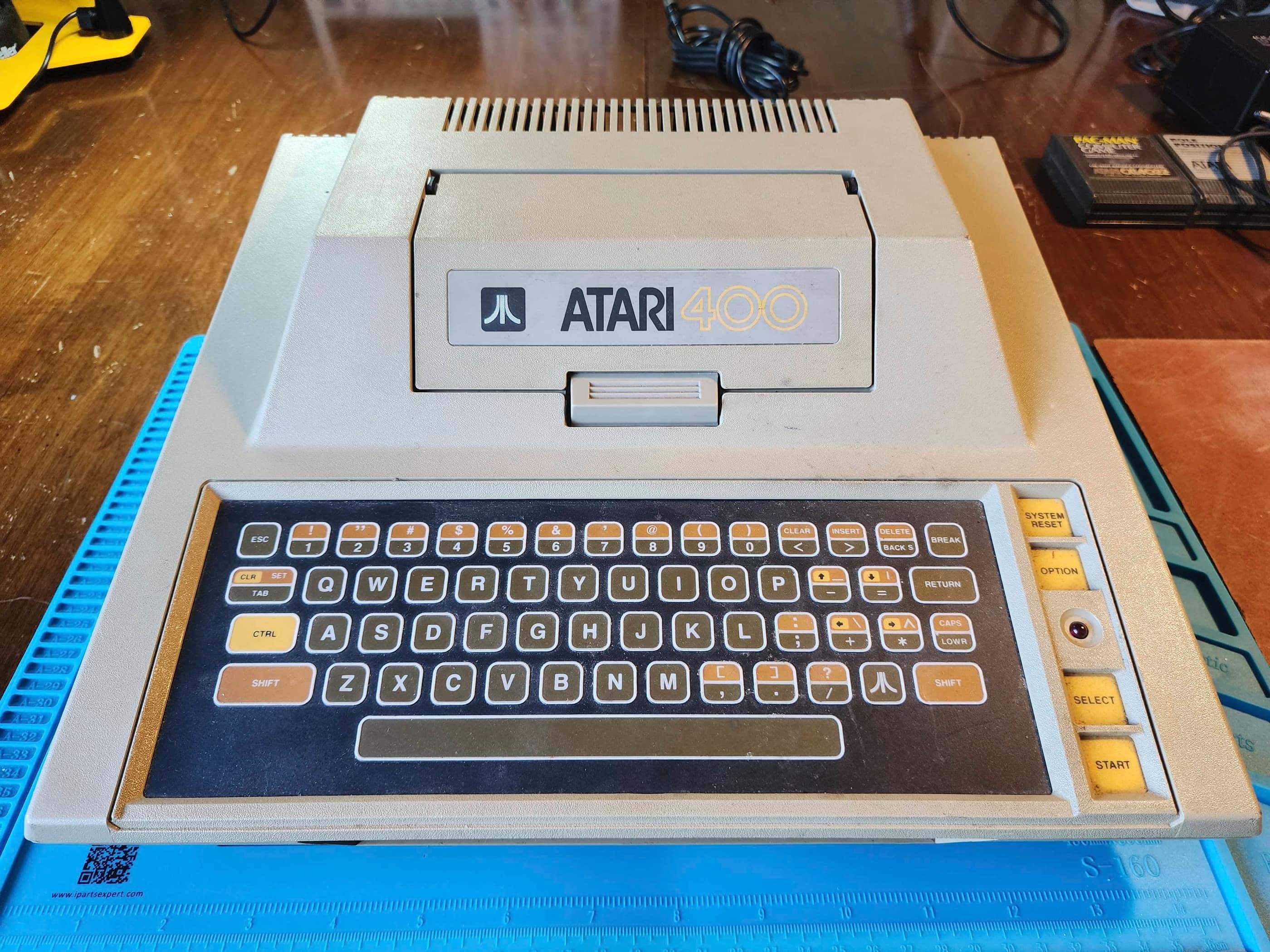
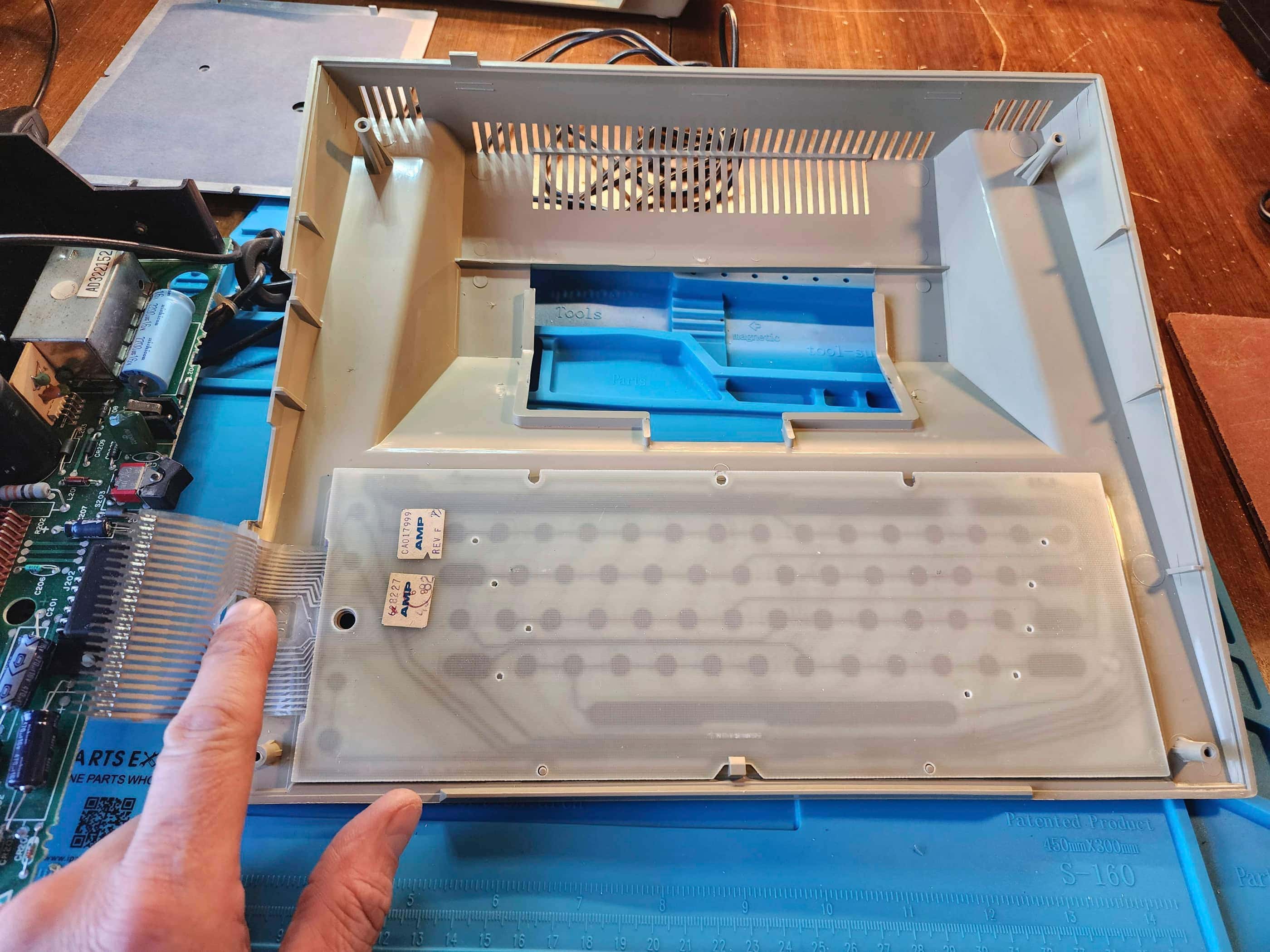
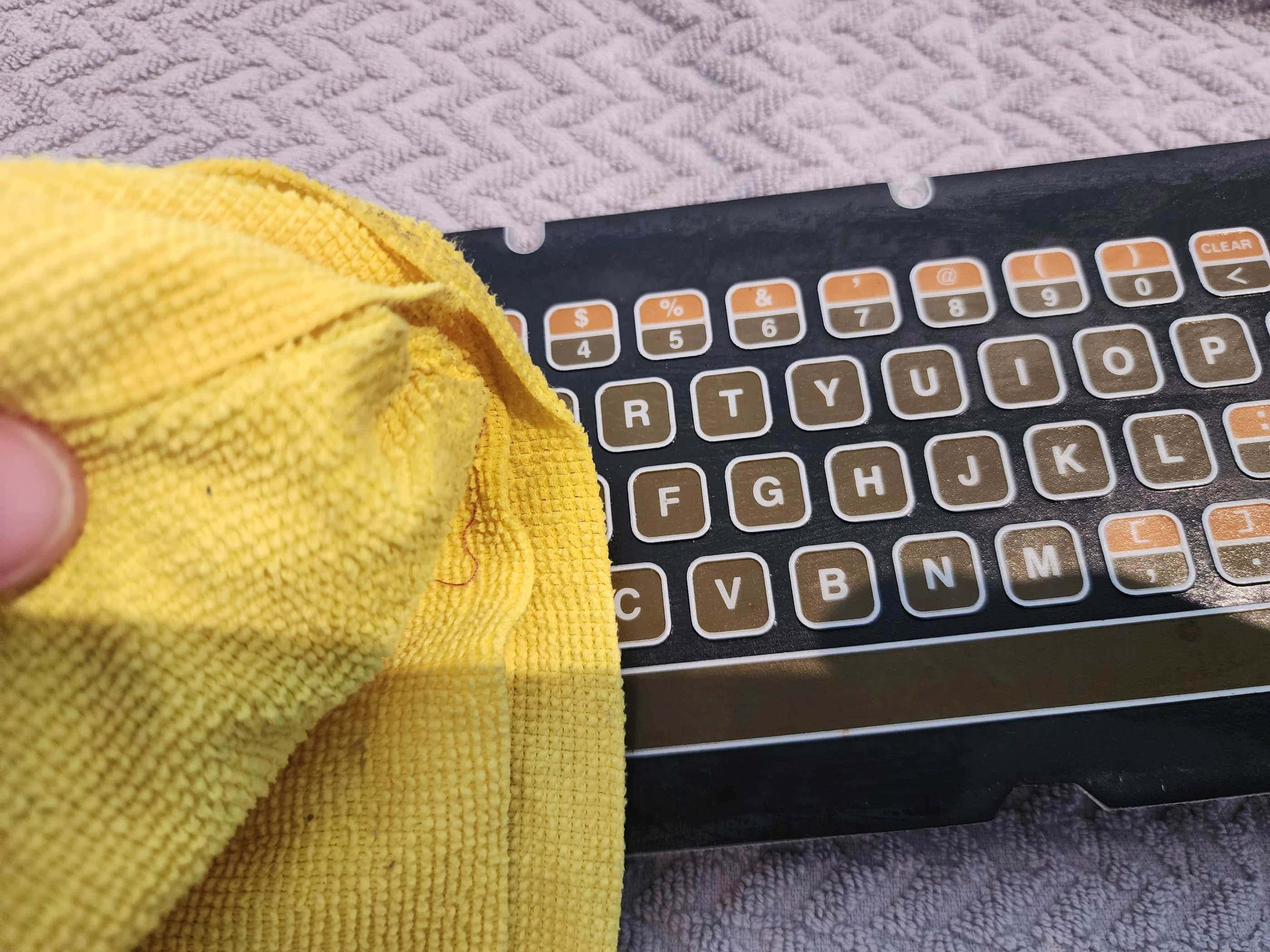
Interesting Fact: Announced in 1978 and released in November 1979, the Atari 400 and 800 were the first efforts by Atari to enter the nascent home computer market. Originally intended to ship with 4K and 8K ram respectively – hence, the names 400 and 800 – a reduction in the cost of chip production meant that the 400 could launch with 16K of ram while the 800 had 48K. (source) Designed by a team that included Jay Miner, who would go on to design the Amiga 1000, the 400 was geared towards children with its wipeable, membrane keyboard that would not only make it easy to clean up after sticky fingers, but also prevent accidental choking from unintended key removal. (source)
Condition When Acquired: Fully Functional
Current Condition: Fully Functional


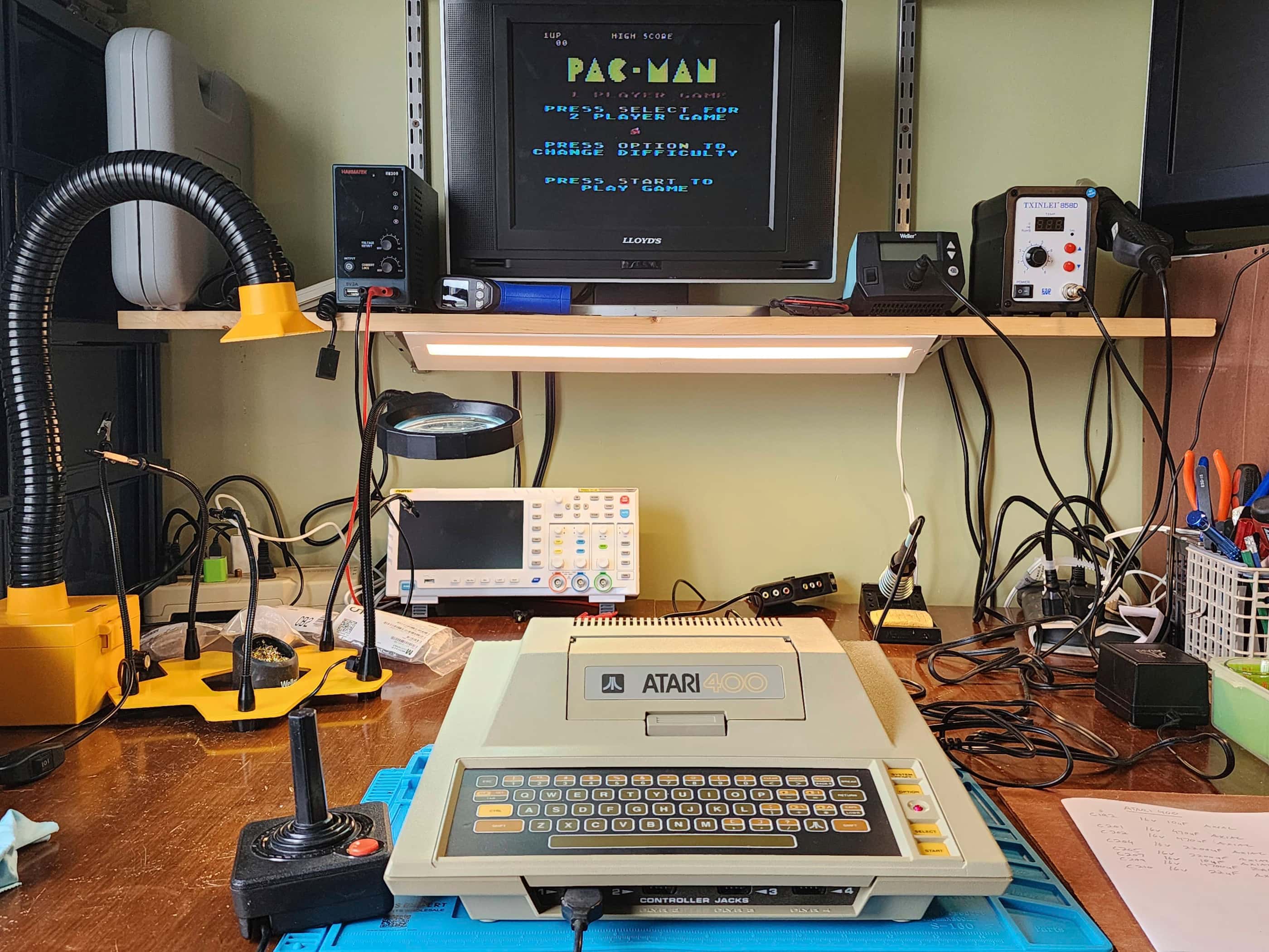


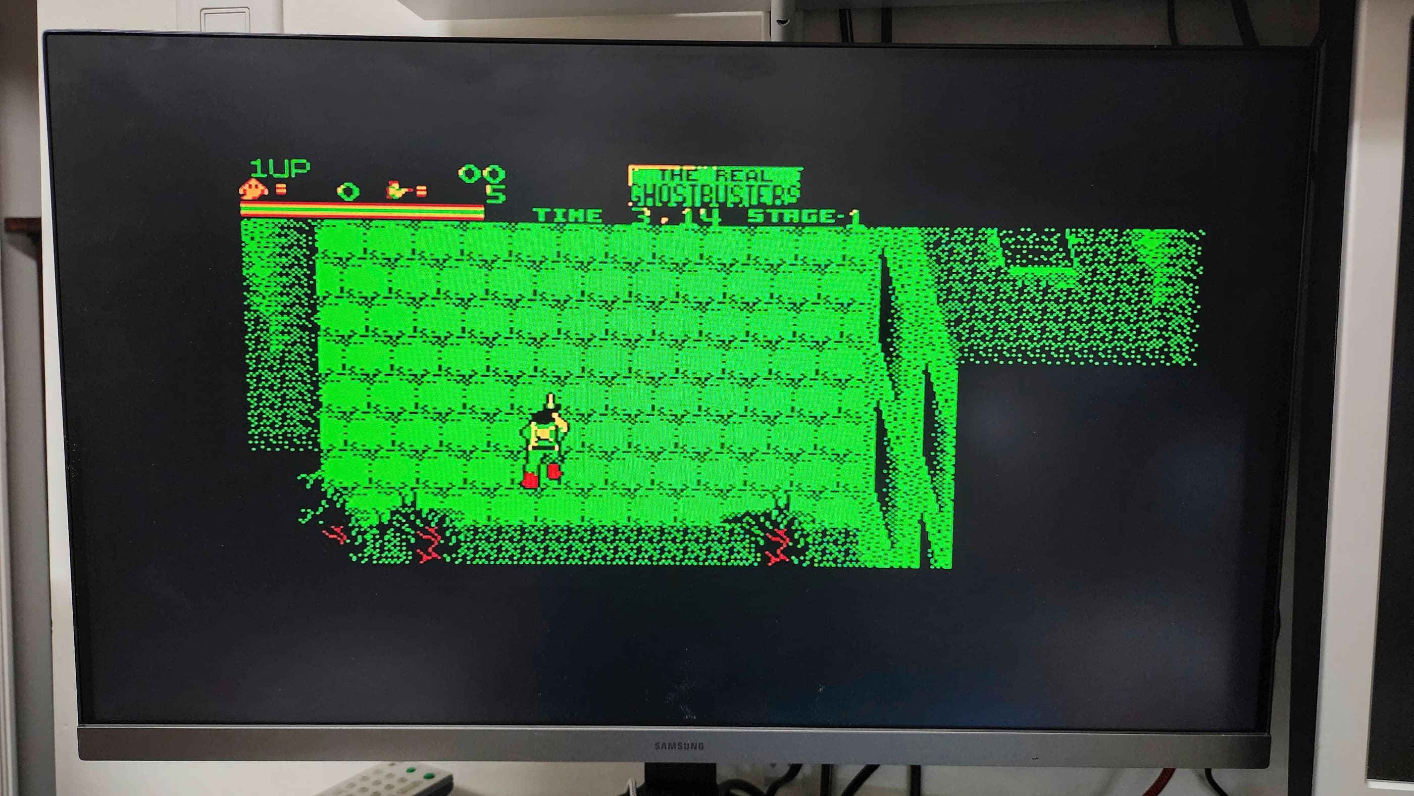
Project Details: I have to say, had I received an Atari 400 instead of a VCS back in 1980, I may have stuck with Atari when it came to buying subsequent computers throughout the 80s. The 400 is a fantastic little machine that has quickly become one of my all-time favourite systems. 🙂
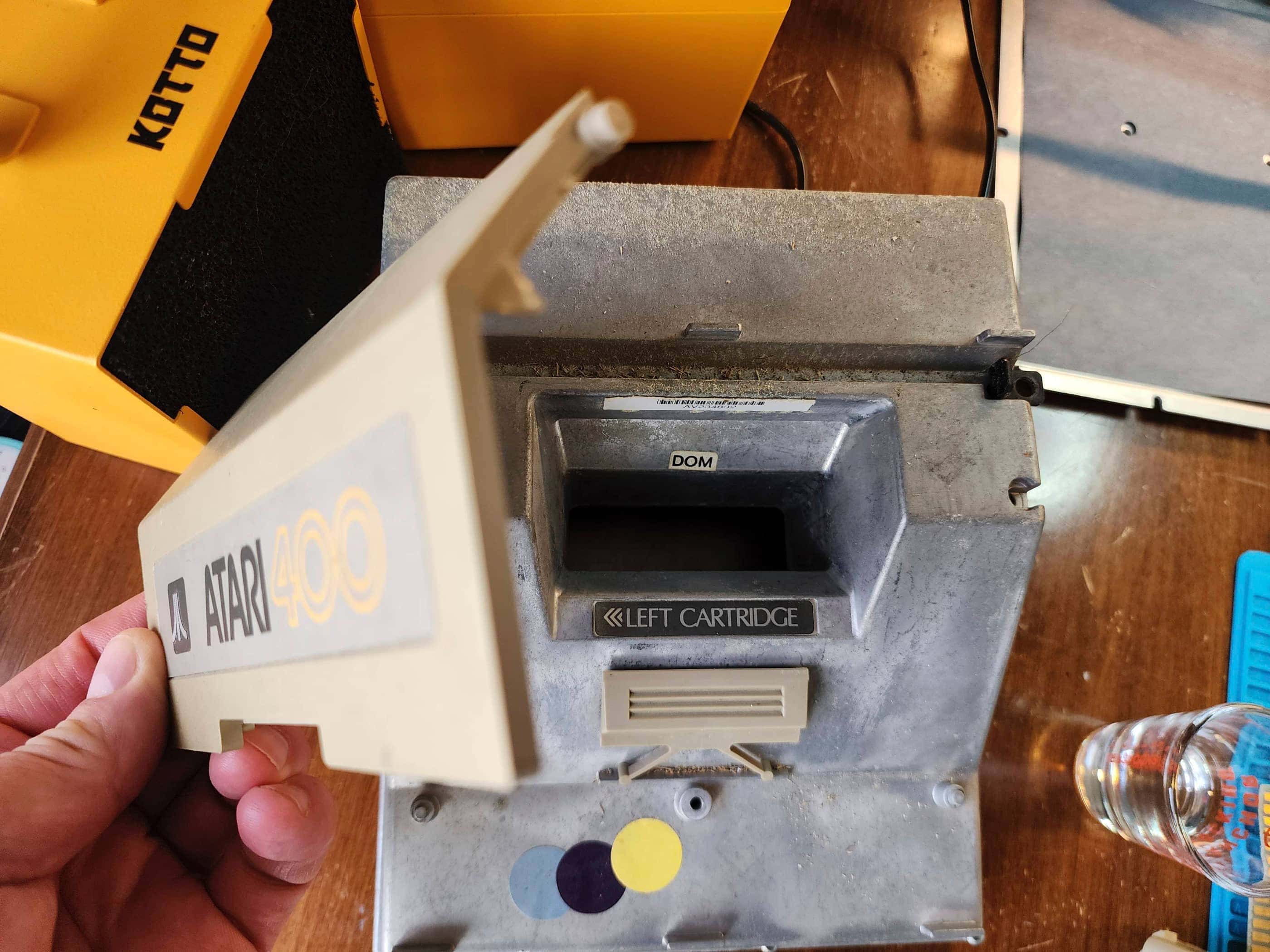
I purchased this unit from my local retro store, Blast From the Past, where it had been sitting in storage for many, many years. Not knowing if it would work, I first tested the power supply and after noting a healthy 10.2 VAC (unloaded), I was pleasantly surprised when the 400 fired up right away. That all of the keys on the membrane keyboard worked flawlessly, was even better.
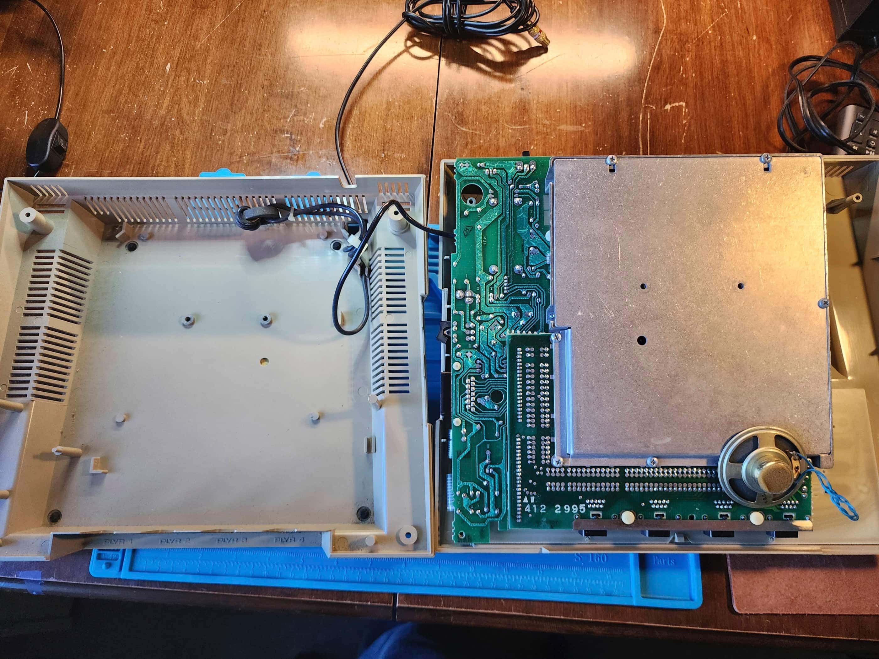
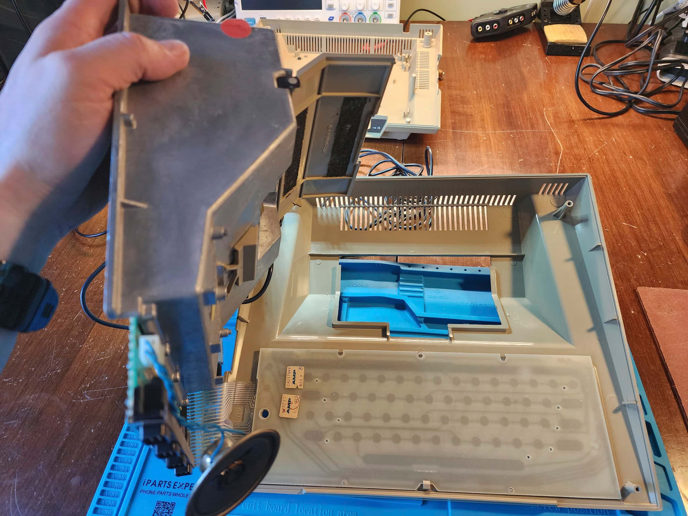
The only drawback was the machine was dirty after being in storage for what I gather, may have been a few decades. In fact, it looked like at some point, it had been in a barn or a farm building as there was grain (or something like grain) scattered inside the cartridge slot and across the tank-like RF shielding. This made me wonder if it had seen a few freeze-thaw cycles during its life, which would make replacing the capacitors a consideration.
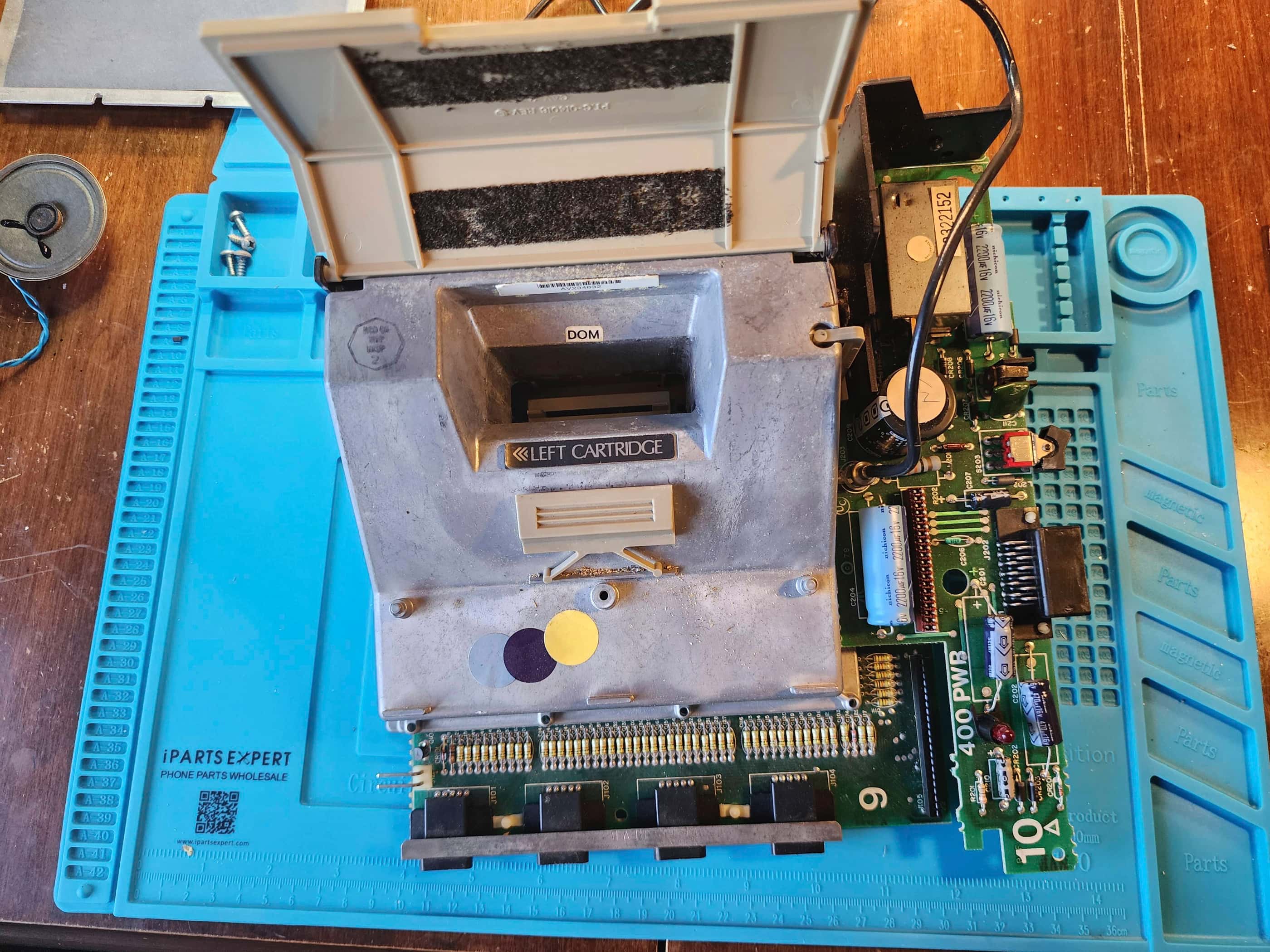
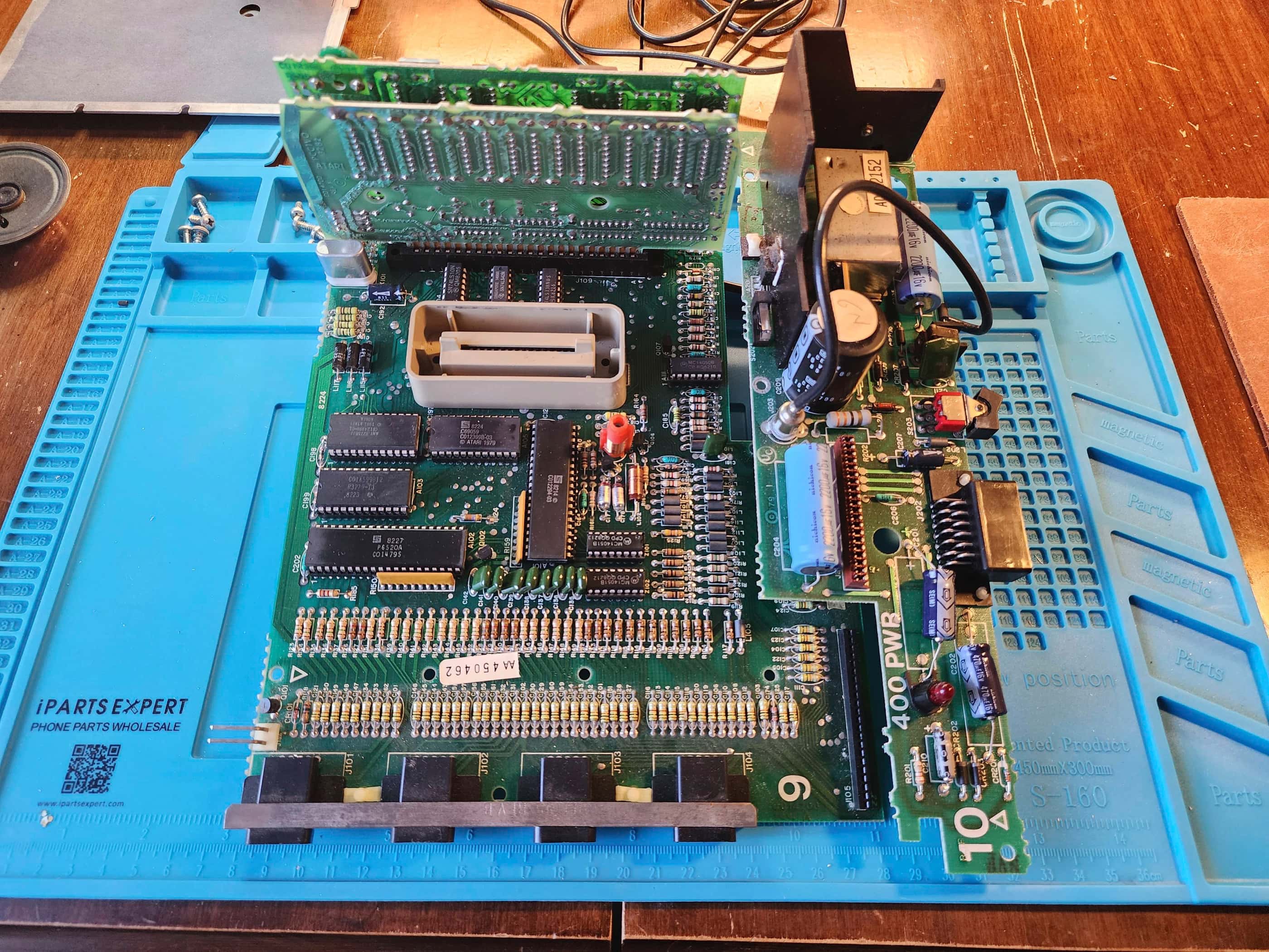
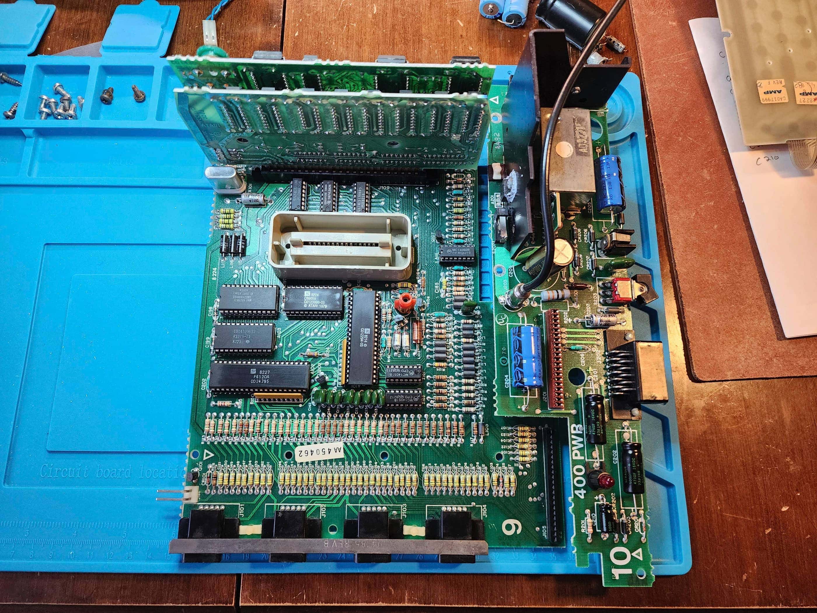
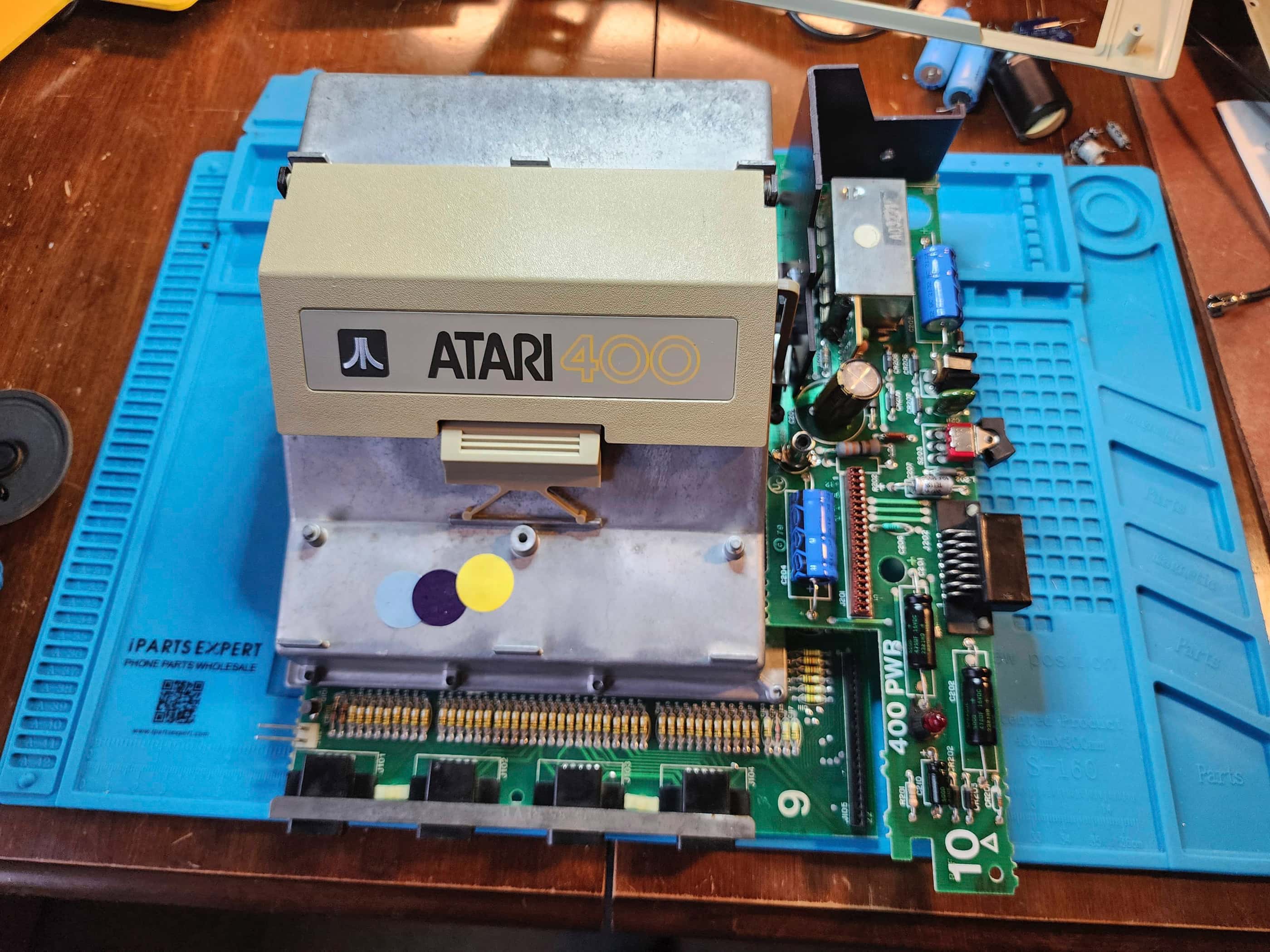
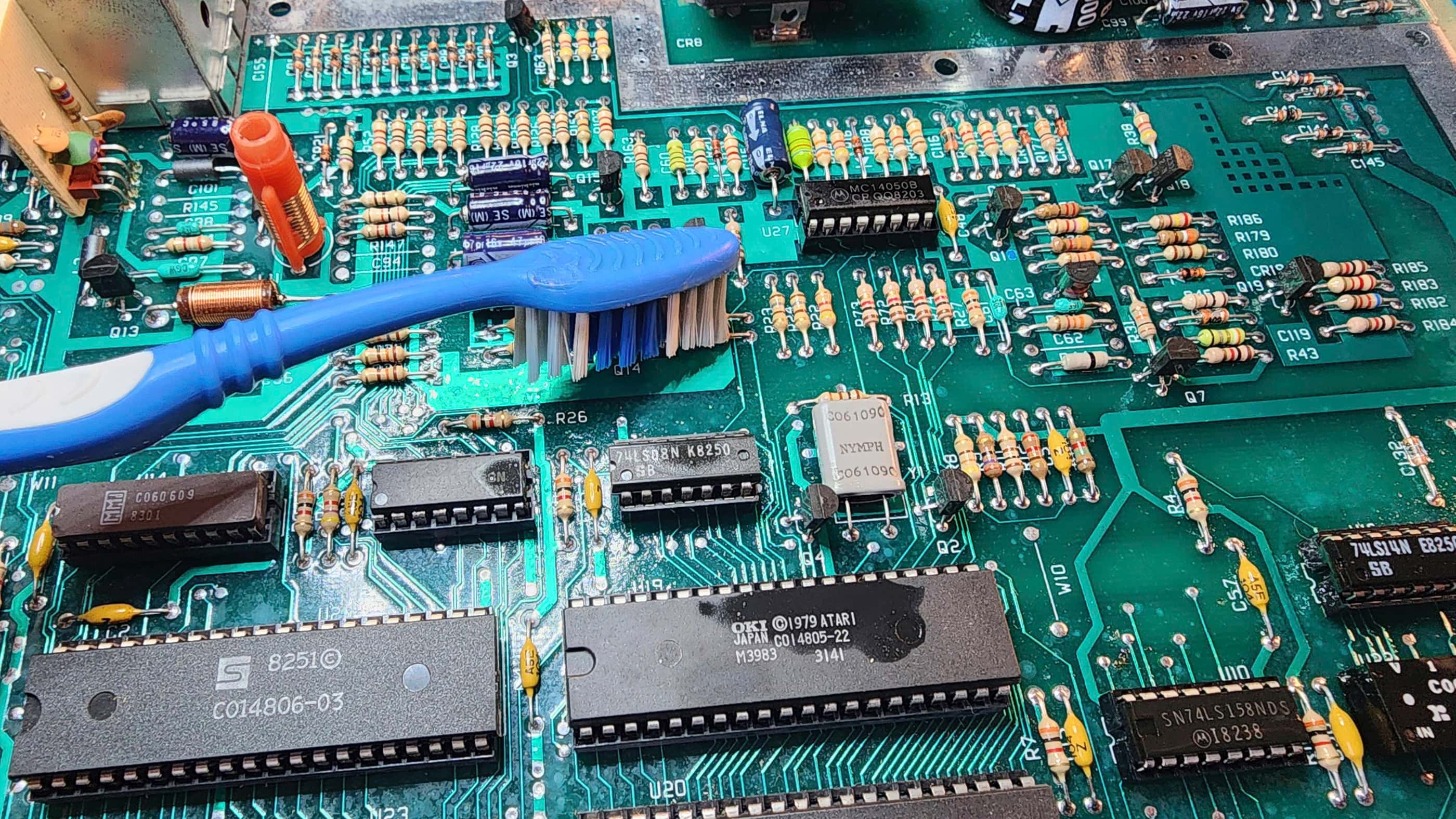
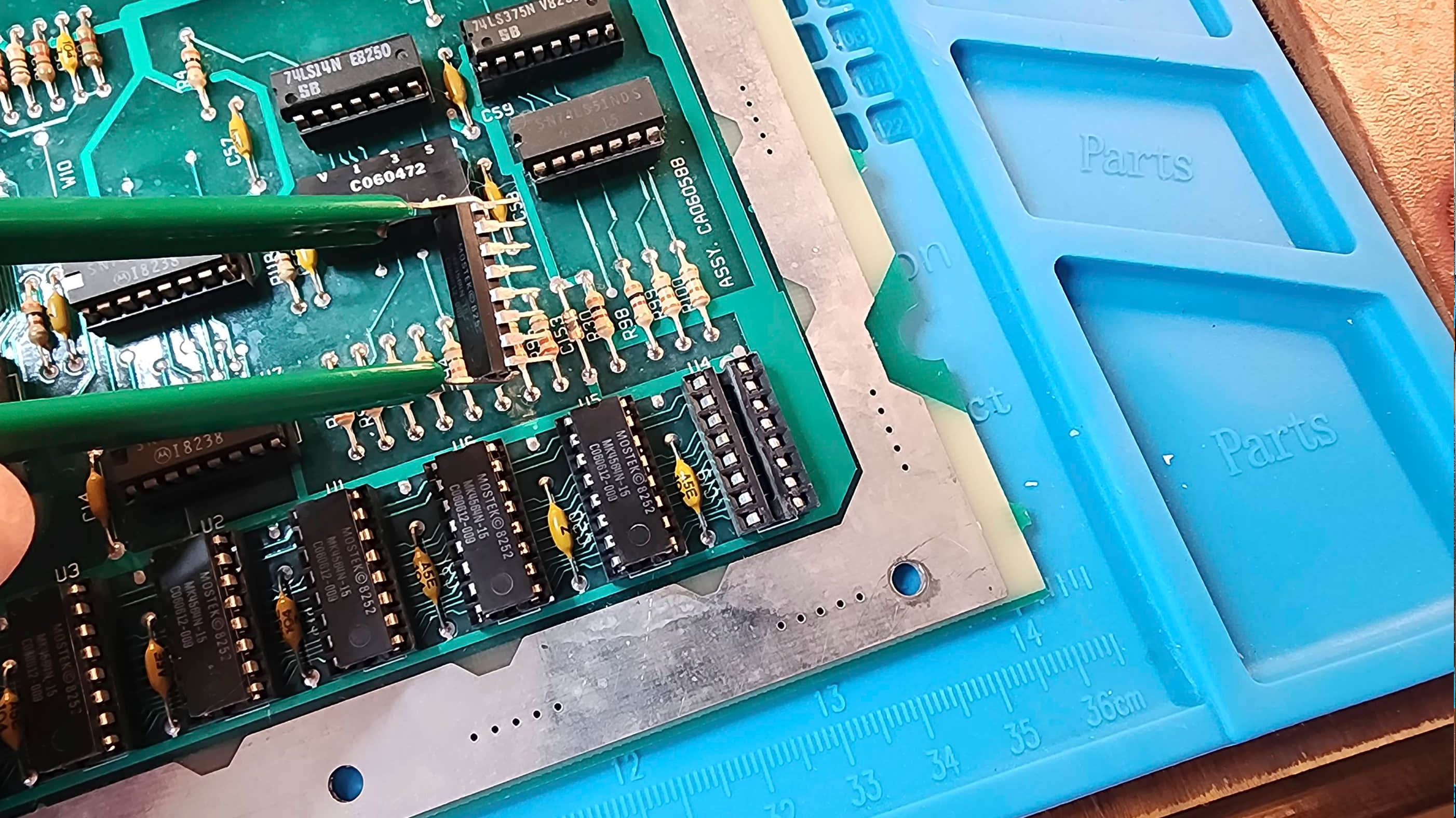
As I disassembled the unit, it was evident that when this was made, Atari still emphasized quality. The cast aluminum RF shielding was a sight to behold as was the PCB with its power supply daughter board and vertical slots for the CPU card and the 16K ram card. I quickly noted that all the capacitors were axial except for the large 16v 4700μF capacitor. I also noted that only one capacitor was located on the main PCB, while the remainder were housed on the power supply. As I had some caps on hand, I placed an order to Mouser for the rest.
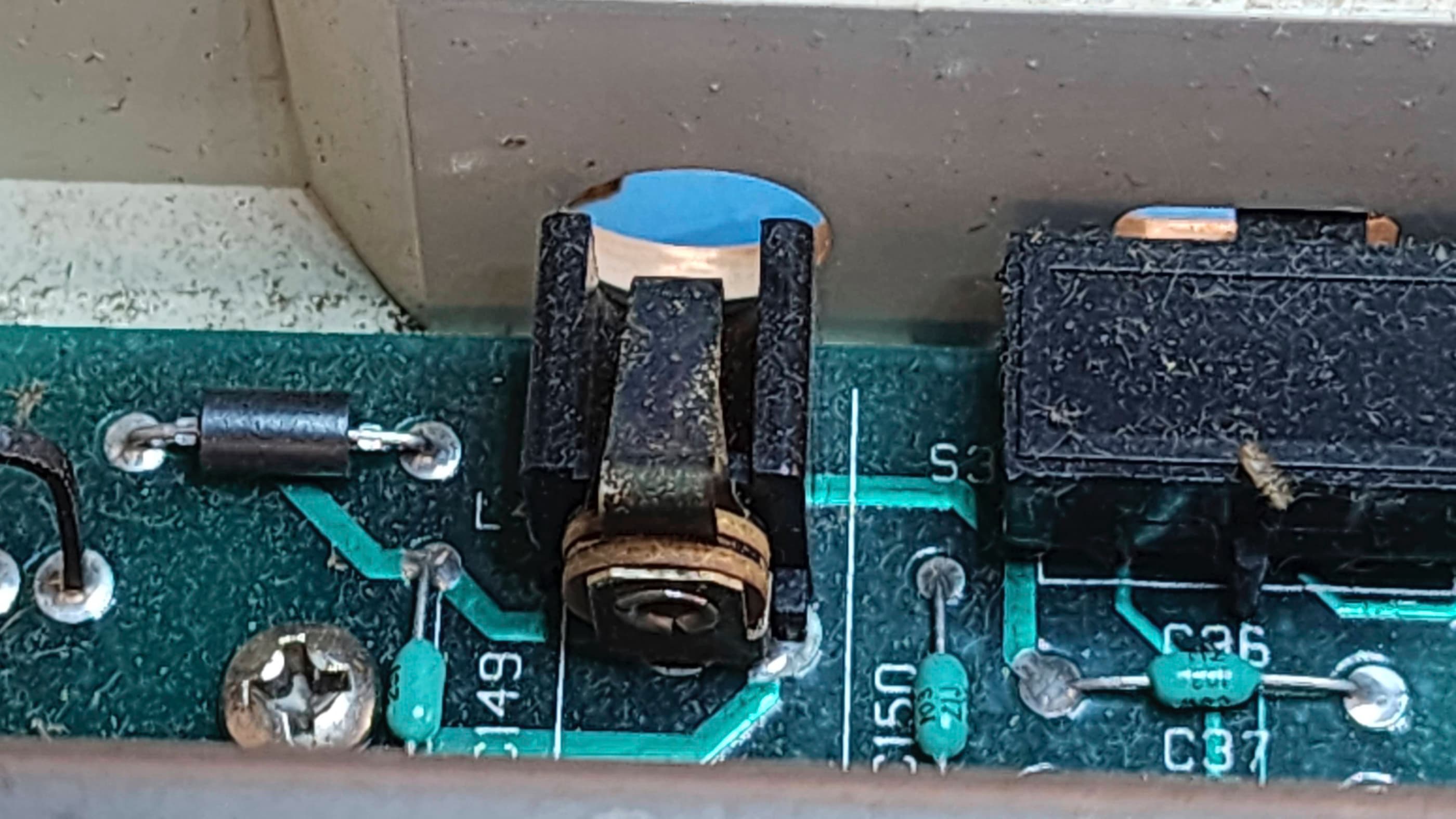
While inspecting the board and components, my attention was drawn to the RF jack which was quite corroded. It still worked, but it had reached the end of its life. Fortunately, I had a replacement on hand. This corroded part lined up with a few of the corroded screws that I had to remove during disassembly, which led me to further believe this unit had been stored in a dry, but temperature-variable environment.
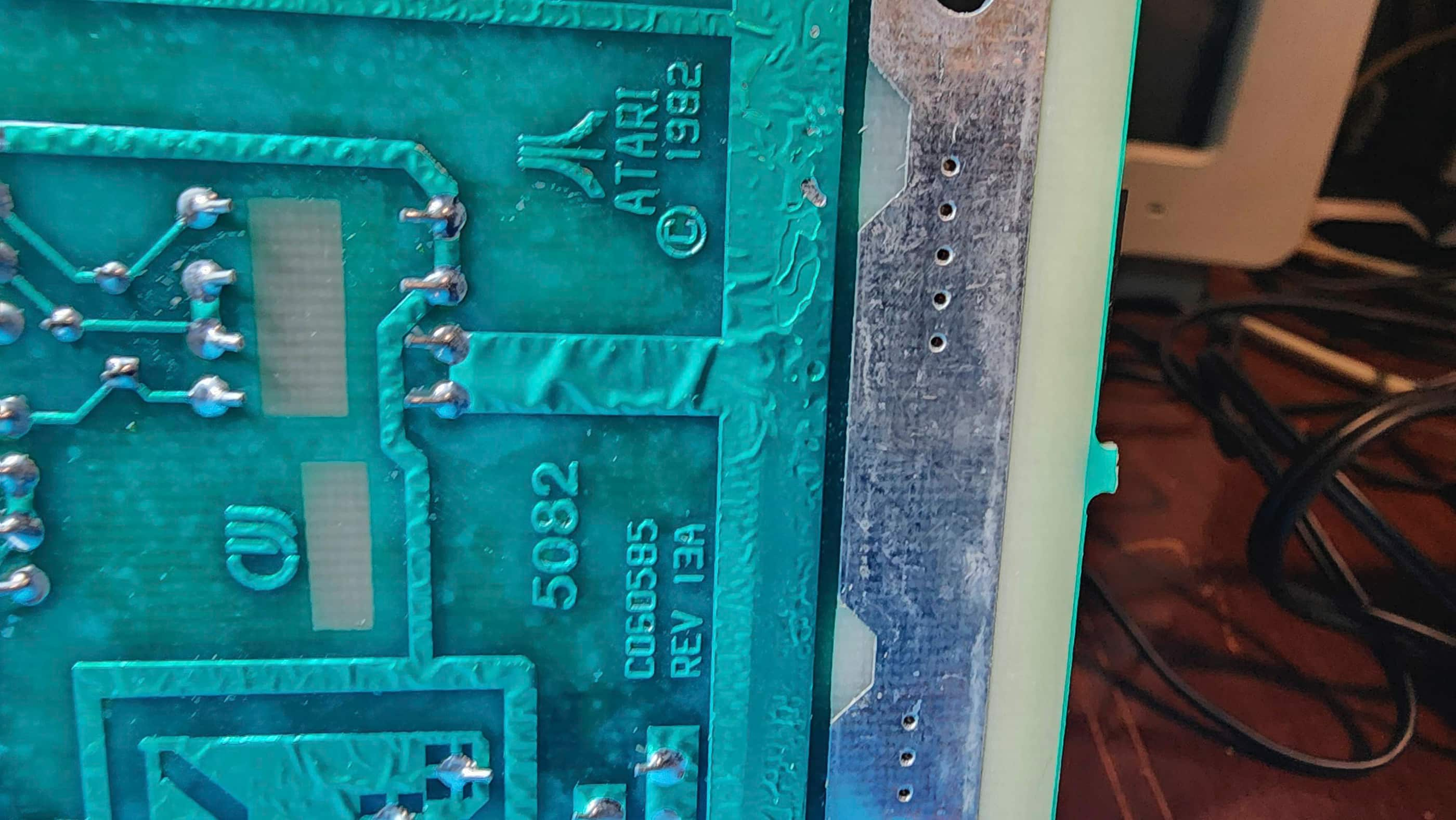
I also made note of the date stamps on the chips and on the board itself. Knowing the production run for these units went into the early 80s, I thought it was cool that I couldn’t find a date later than 1979. This indicated to me, that it was probably manufactured in or at least close to its 1979 release.
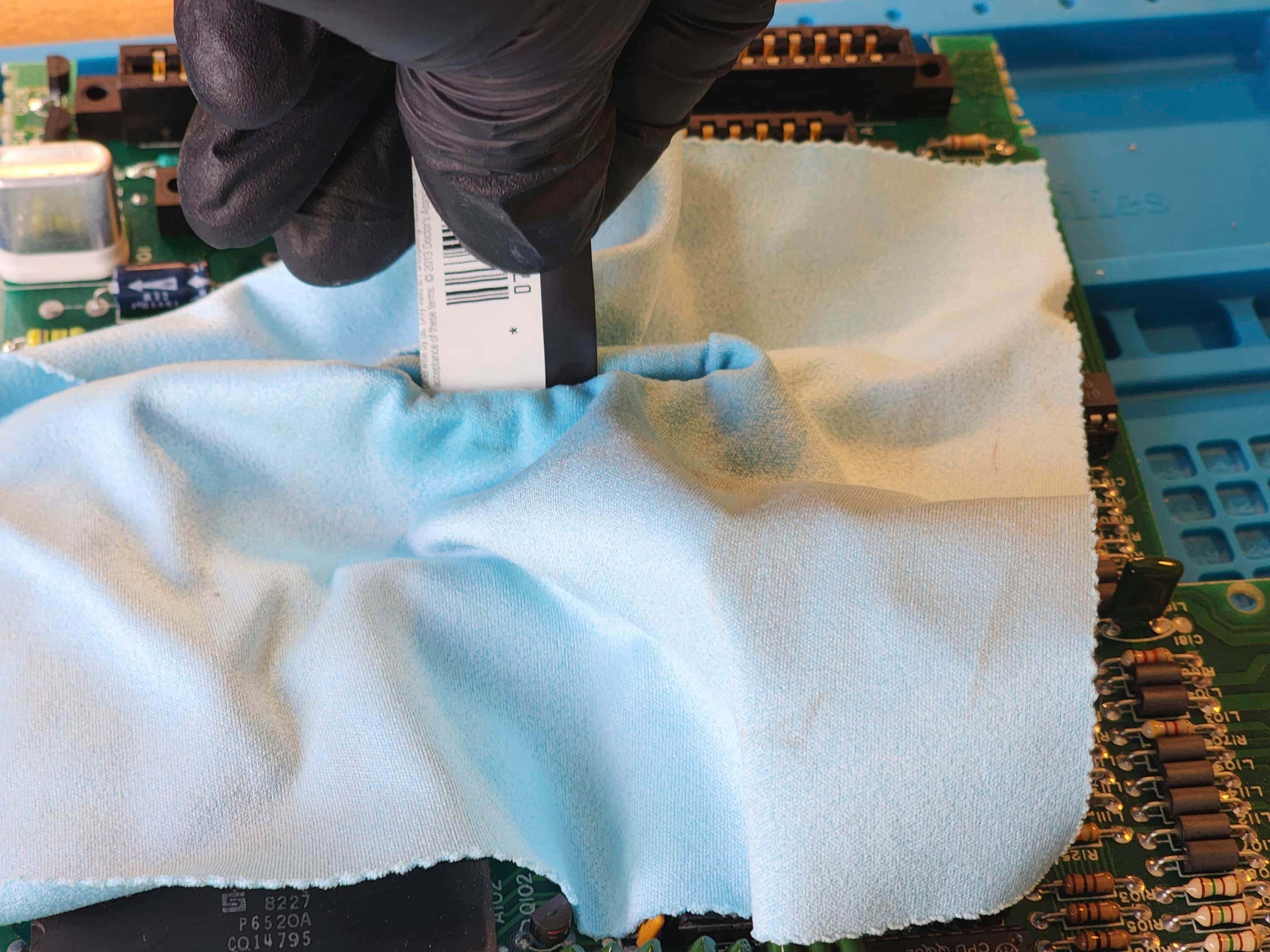
Anyway, the cleaning process went well and soon the case and board were looking ship-shape. Re-capping did not take long, nor did replacing the replacing the RF jack. As there was a fairly good RF output including audio, I saw no need to put in a composite mod. I also left the 7805 and 7812 voltage regulators as they were, except for removing and replacing the old thermal paste. I considered replacing the regulators, but as I did not have the correct 7812 on hand, and as it was working properly, I simply left it.
After testing, I reassembled the machine and tested it again for an extended period. Everything worked well and I’ve since had fun playing different games on this system – and so have my kids. Again, had I received this in 1980, I may well have been an ‘Atari computer’ guy; eventually ending up with an ST instead of an Amiga… then again, maybe I’m just a fan of Jay Miner’s work. 🤔
Parts & Products Used: 99% isopropyl alcohol; Chemical Guys Natural Shine; thermal paste; PCB RF jack (1); electrolytic capacitors (axial) – 16v 10 μF (2), 16v 22μF (1), 16v 470μF (2), 16v 2200μF (2); electrolytic capacitors (radial) – 16v 4700μF (1)
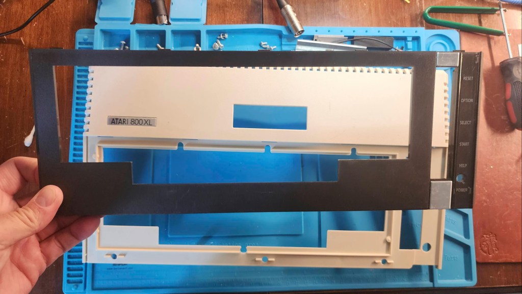
Atari 800XL
Years (1983-1985)
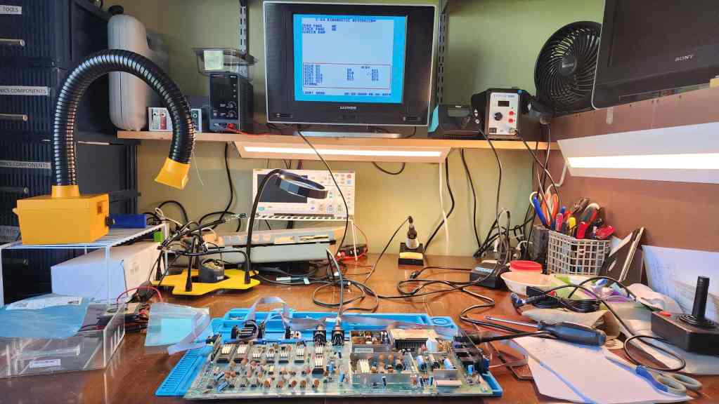
Interesting Fact: The 800XL was a cost-reduced version of the original Atari 800. (source) It had 64K of memory and the same “custom chips (Pokey, GTIA, Antic) of the previous models”; though the Antic chip had been enhanced to allow for 16 graphics modes as opposed to 12. (source) The 800XL was mostly backwards compatible with previous 400/800 software, but some program did not work and so Atari created a translator version of the OS that could support the previously incompatible software. (source) Notably, the 800XL did not have the same video output quality as the original 800 (hence, the popular S-video mod), but it did include Atari BASIC built-in along with a diagnostics program. (source) It would be replaced in 1985 by the XE line of Atari computers.
Condition When Acquired: Fully Functional
Current Condition: Fully Functional


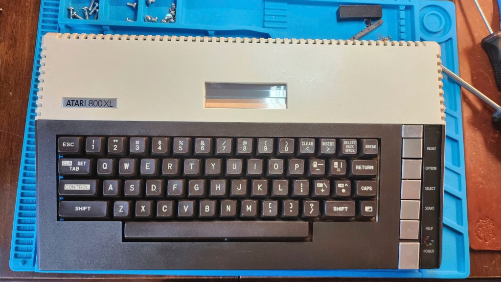


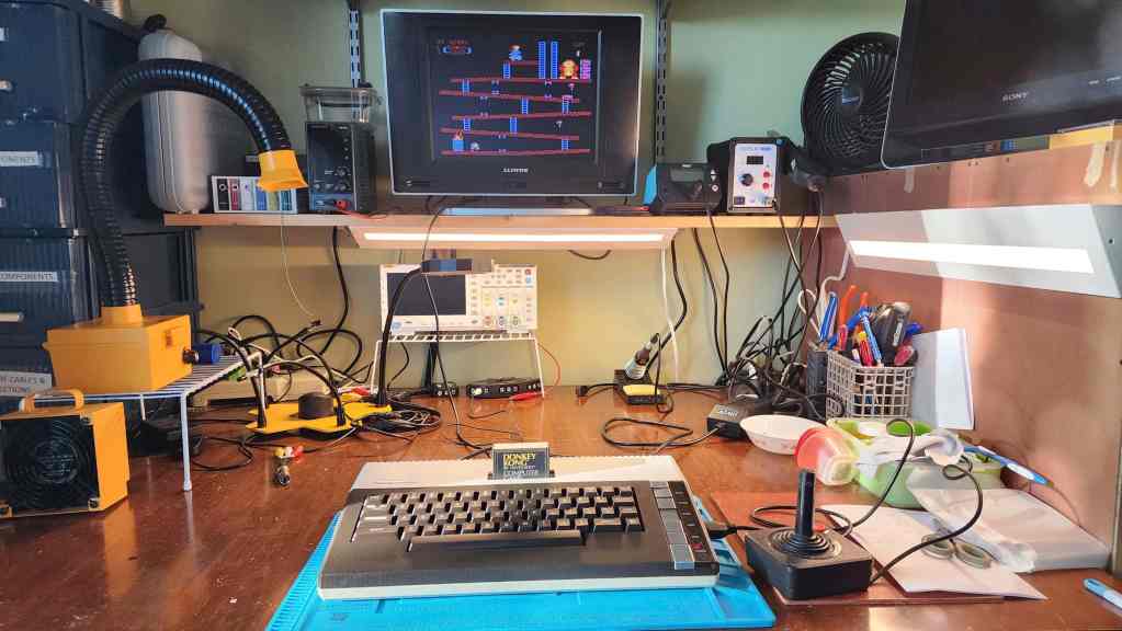


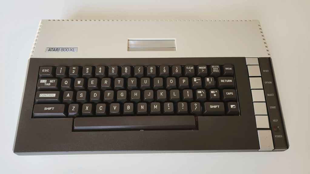
Project Details: Finding a working 800XL in great shape was a wonderful find. Paying what I did for it, was something to celebrate. When coupled with the working Atari 1050 5 ¼” floppy that I had previously acquired, I now had a rival 8-bit system to the Commodore 64. In fact, I was excited that I could now do a side-by-side comparison.
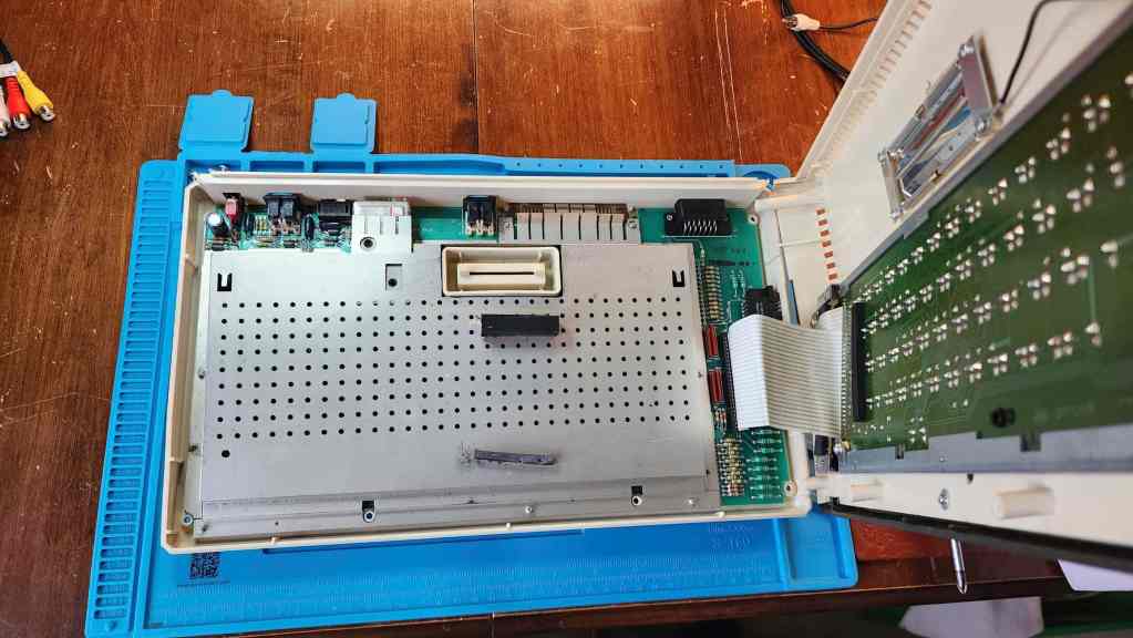
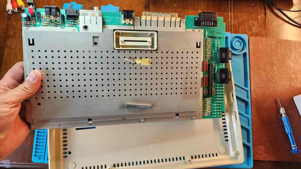
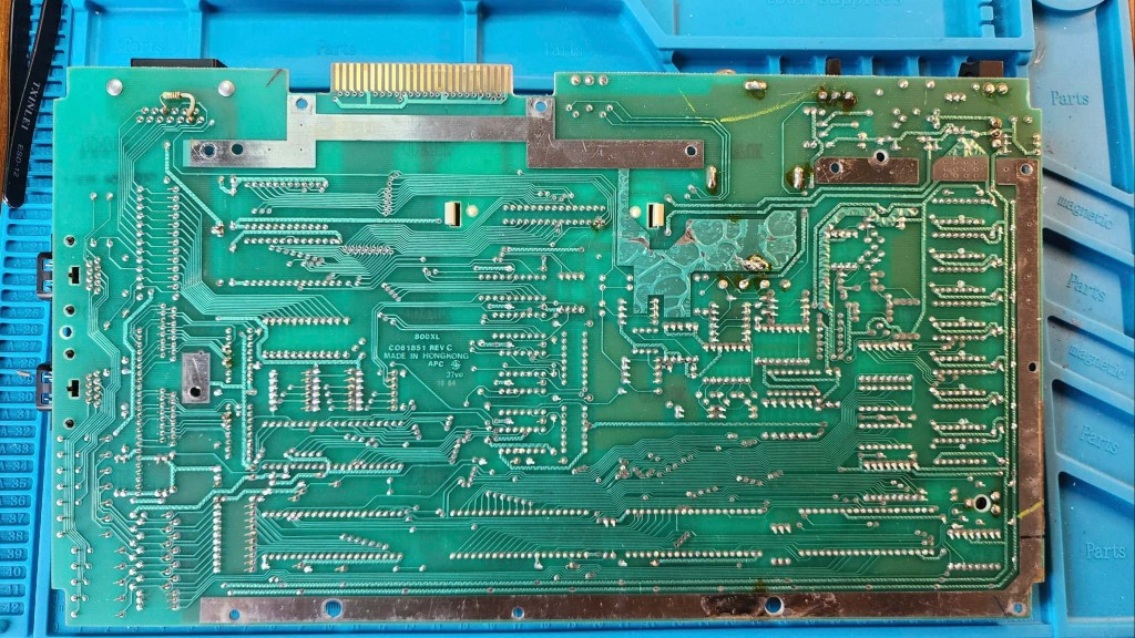
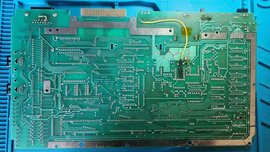
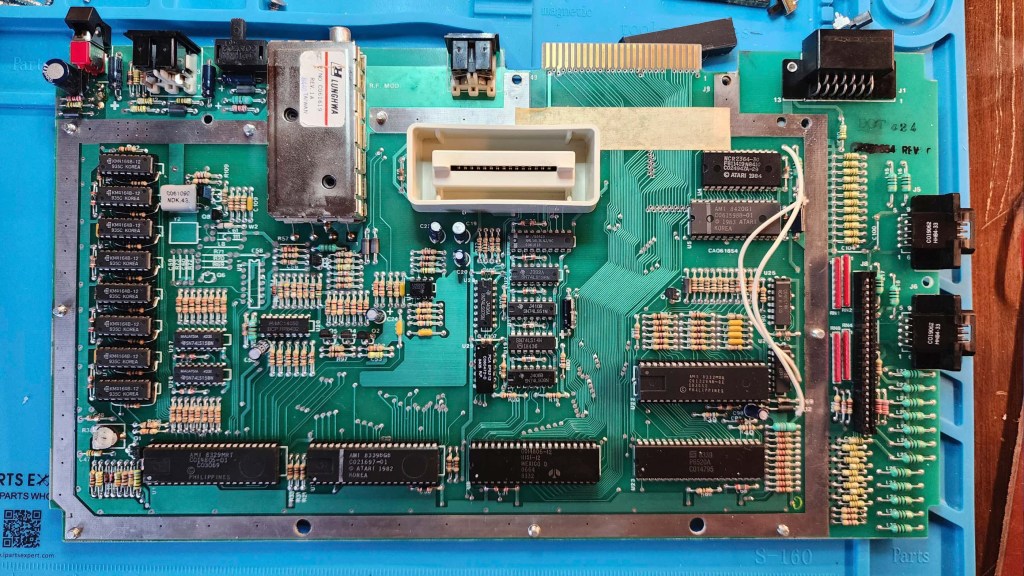
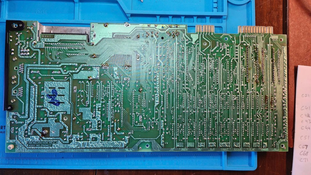
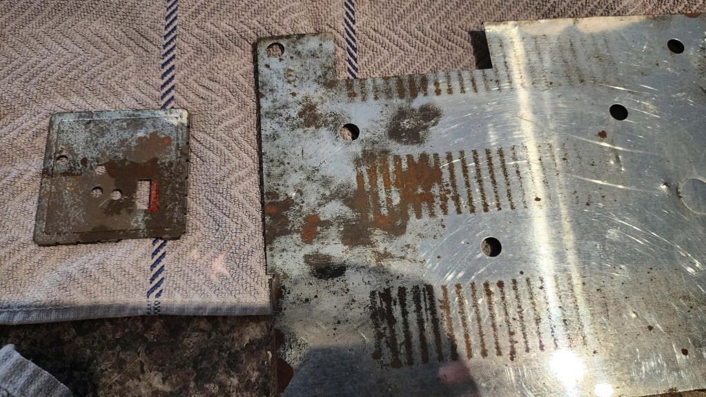
On opening the computer, I could tell that it was unlikely that anyone had done past work or mods to the board. The first thing I noted, was the rusty RF shielding that on the bottom, had leached onto the board near the parallel port. That wasn’t good, but it looked fixable.
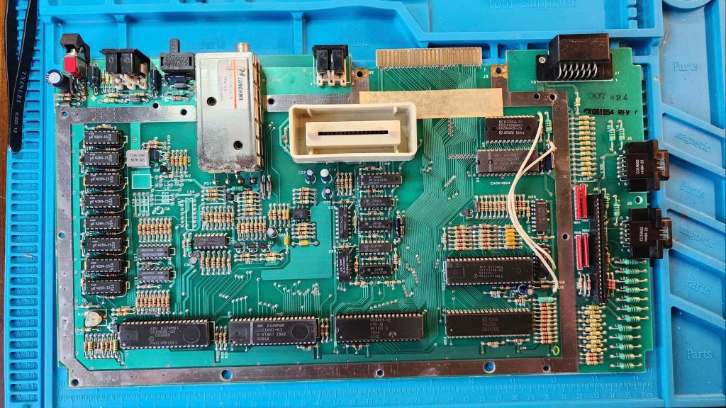
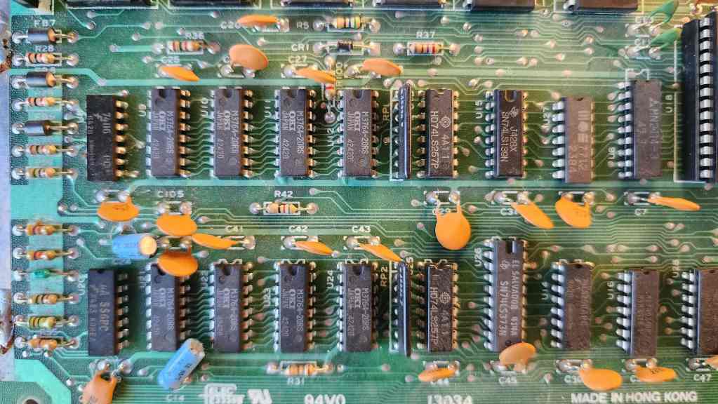
The second thing I noticed were the eight MT 64K x 1 DRAM chips (4264-15). MT is short for Micron Technology Inc., which is a Fortune 500 chip manufacturer that started in 1978. Their 64k DRAM chips were launched in 1981 and were used in many of the major 8-bit computers, including the C64 and the 800Xl. What I’ve learned from folks in the know, such as Adrian Black, is that these MT ram chips from the early to mid-80s, are highly prone to failure. The chips on this particular computer were still good, but from all that I’ve read and watched, it is only a matter of time before they deteriorate. Thankfully however, they were all socketed, so replacing them for preventative purposes wouldn’t be hard.
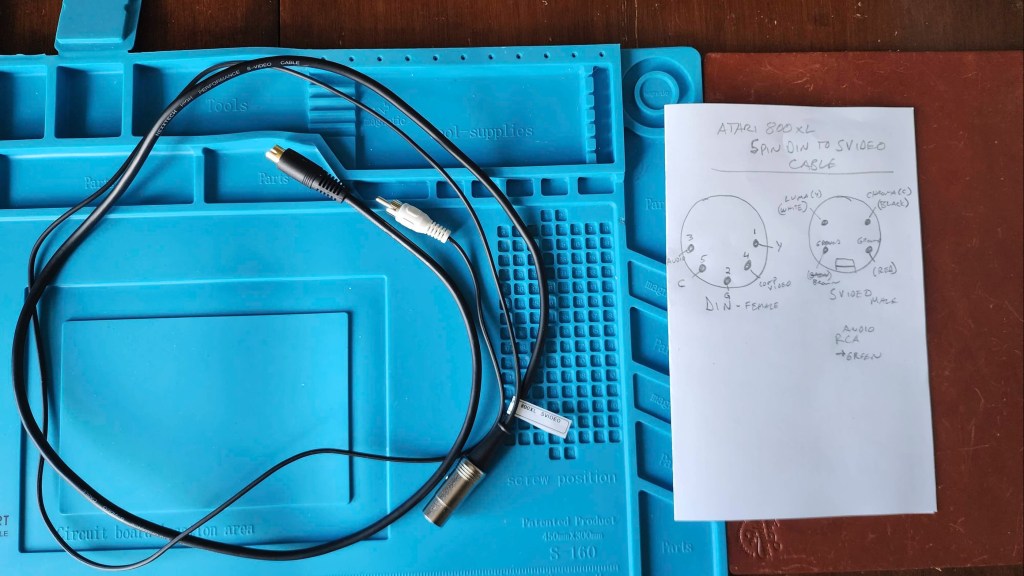
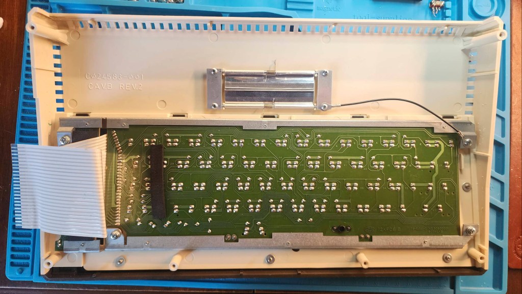
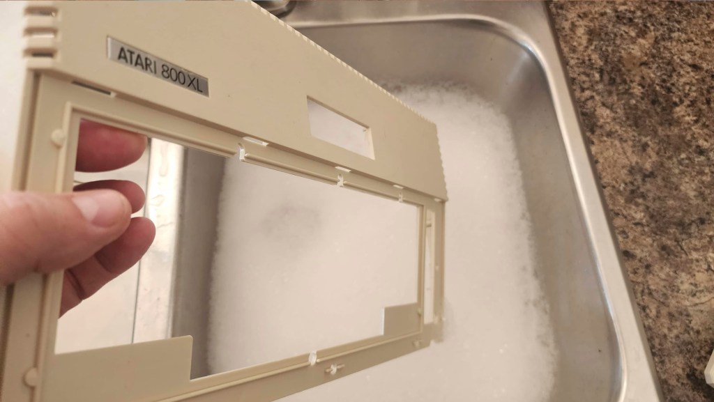
The third thing I noted, was that no one had performed the popular S-Video mod by running a chroma wire from R67 / R68 to pin 5 on the video DIN jack. That this hadn’t been done, also confirmed to me that the board had probably not been touched since it left the factory. Finally, I noted that the keyboard was also very dirty and that it would take more than a simple dusting to clean it.
With this short list, I started working on the computer. That’s when I realized that I didn’t have an Atari 5 pin DIN to S-Video cable, so my first order of business was making one by using a male DIN connector and soldering on an old S-Video cable and an old RCA jack for audio. Unlike the C64 S-Video cable, no resistors were needed to dampen the chroma, so it was a simple matter of identifying the corresponding wires and soldering them to the right pins on the DIN connector.
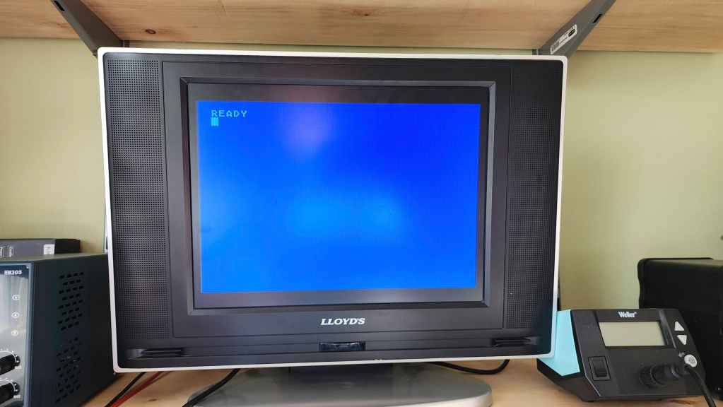
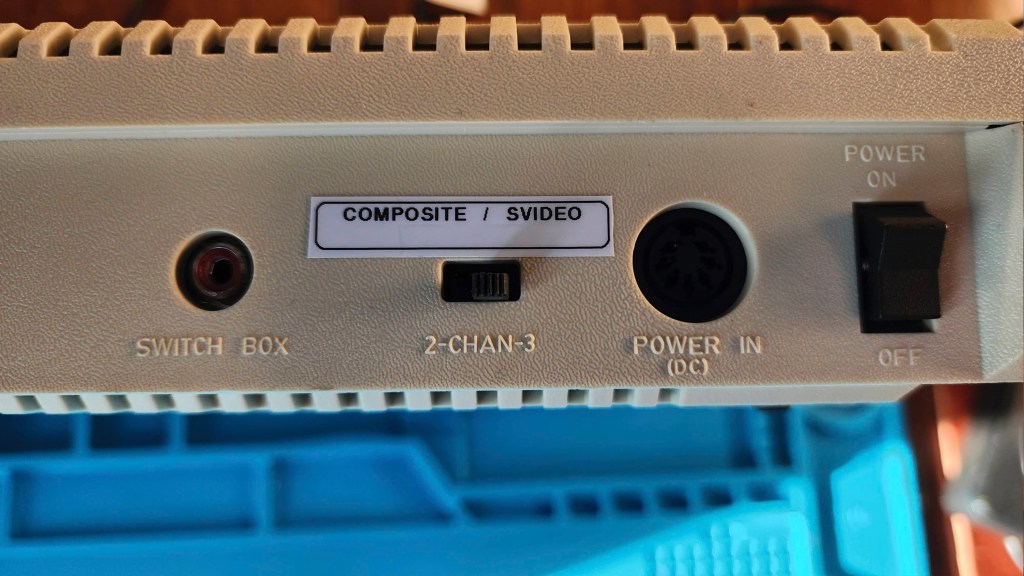
Next, it was a super easy task to add the chroma wire to the video jack and a quick test with my new S-Video cable showed that everything worked. However, the jail bars were quite noticeable and while I had hoped not to have to clip the right leg of C54 to kill the composite signal, I decided to do it and the jail bars mostly disappeared. As I didn’t want the composite signal to be completely killed, I decided to do what was recommended on Atari Age and add a switch to toggle between composite and S-Video.
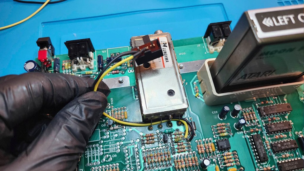
As I didn’t want to cut into the case for the new switch, I toyed with a few possible options. That’s when it dawned on me that the RF modulator channel select switch could be re-worked to be the S-Video / Composite switch. This would keep the authenticity of the computer case and since the RF modulator was probably not going to be used over the composite or S-Video options, altering the channel select switch was the perfect solution.
To mod the switch, I first desoldered it to remove it from ground (it can’t be grounded if you are simply completing the circuit of the cut leg on C54). Next, I soldered two wires from each half of the cut right leg on C54 to the switch. I then flipped the switch upside down (to avoid ground) and used double-sided Alien Tape to affix it to the board. The thickness of the Alien Tape allows the switch to remain at the same height as it normally would be if it were soldered to the board. This ensures that it nicely fits into the slot on the back of the case. With this done, a test showed that everything worked smoothly and I could now toggle back and forth between jail bard free S-Video and composite (with jail bars).
With the S-Video mod complete, I turned my attention to cleaning the computer while I waited for the new DRAM to arrive from Jameco. I wanted a brand name manufacturer, and I couldn’t find a supplier of 4164 chips in Canada, so I had to order it from the U.S. which can take time (and money).
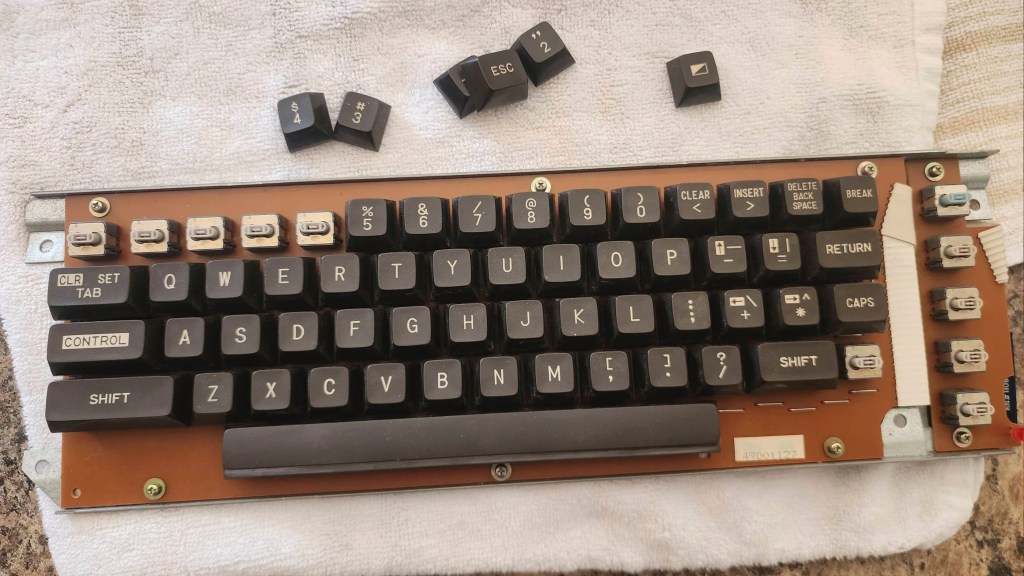
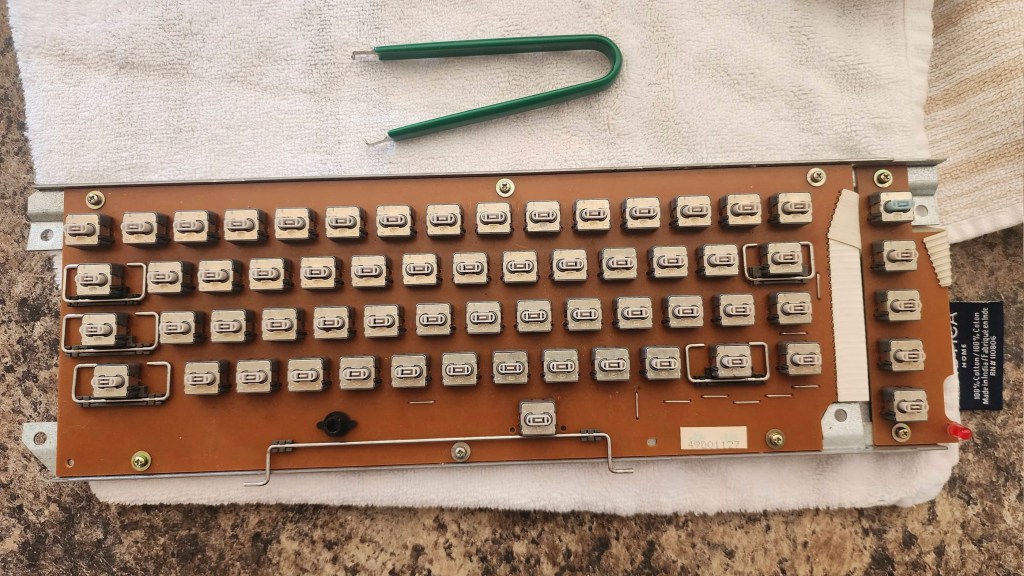
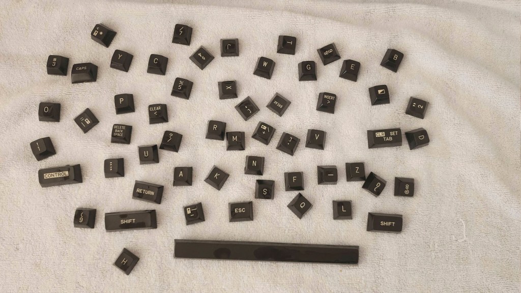
After giving the board a thorough cleaning with IPA and reseating the socketed chips using Deoxit D5, I set about removing each key from the keyboard (I made sure to take a photo first!). I then washed the case halves and keys thoroughly before reassembling the key board. A good shine and UV-proofing with Chemicals Guys Natural Shine had everything looking great. I used a white vinegar solution to clean the rust stains on the board and soaked the shielding in it before scrubbing with steel wool. Unfortunately, I had to cut off a portion of the
Once the new ram came it was a simple install (note it is 120ns and not 150ns like the original MT but the 800XL has no problem with this). Testing showed that all looked good. I then reassembled the entire computer and ran it through more testing and again, it all worked great.
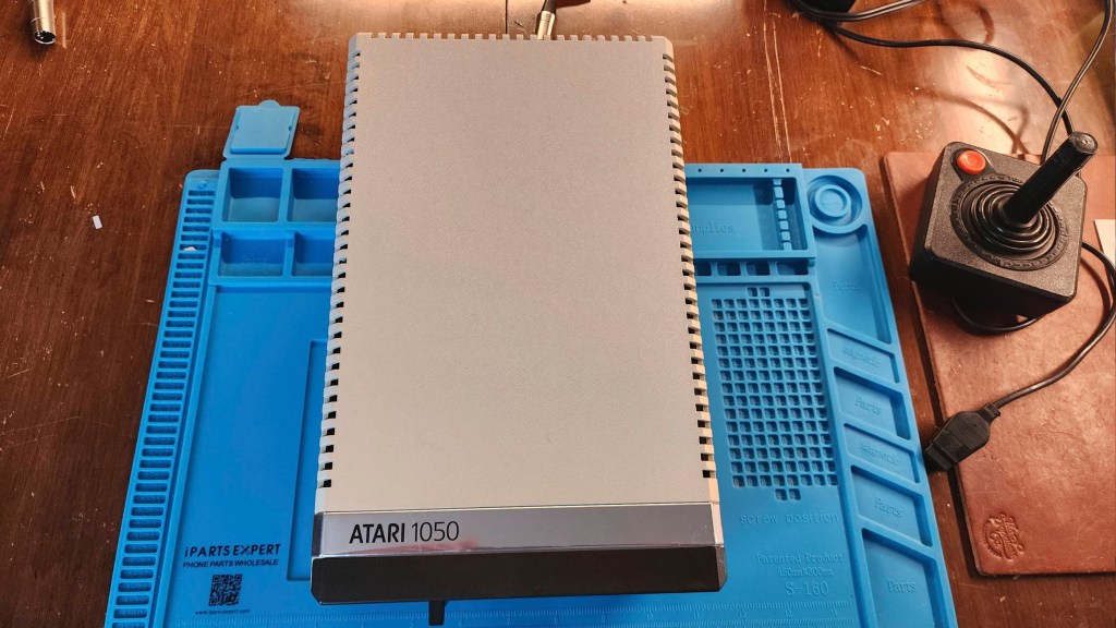
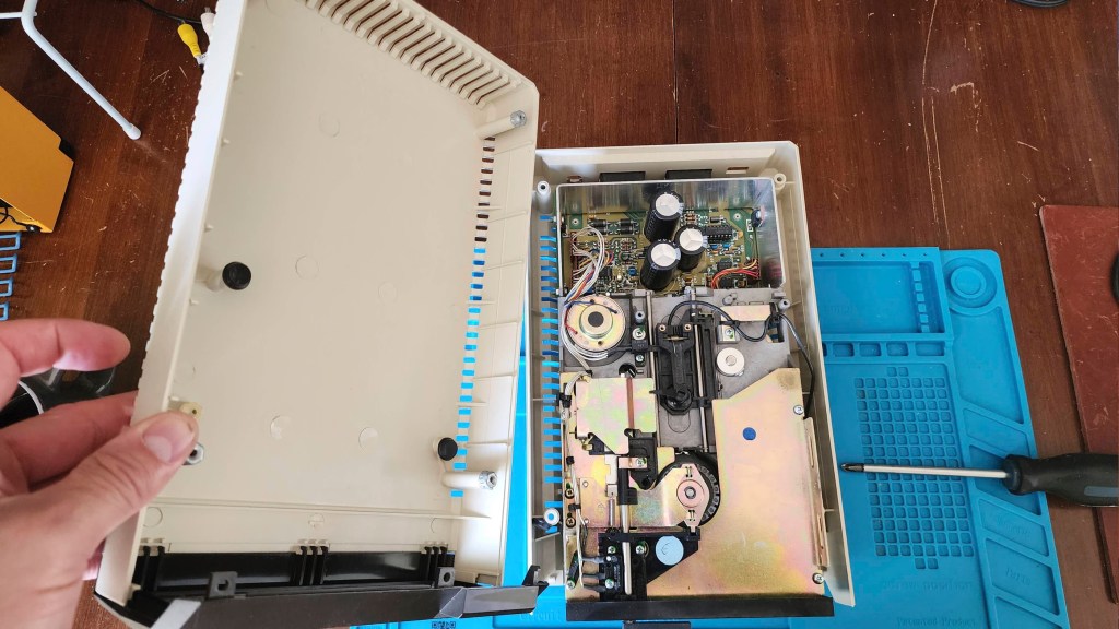
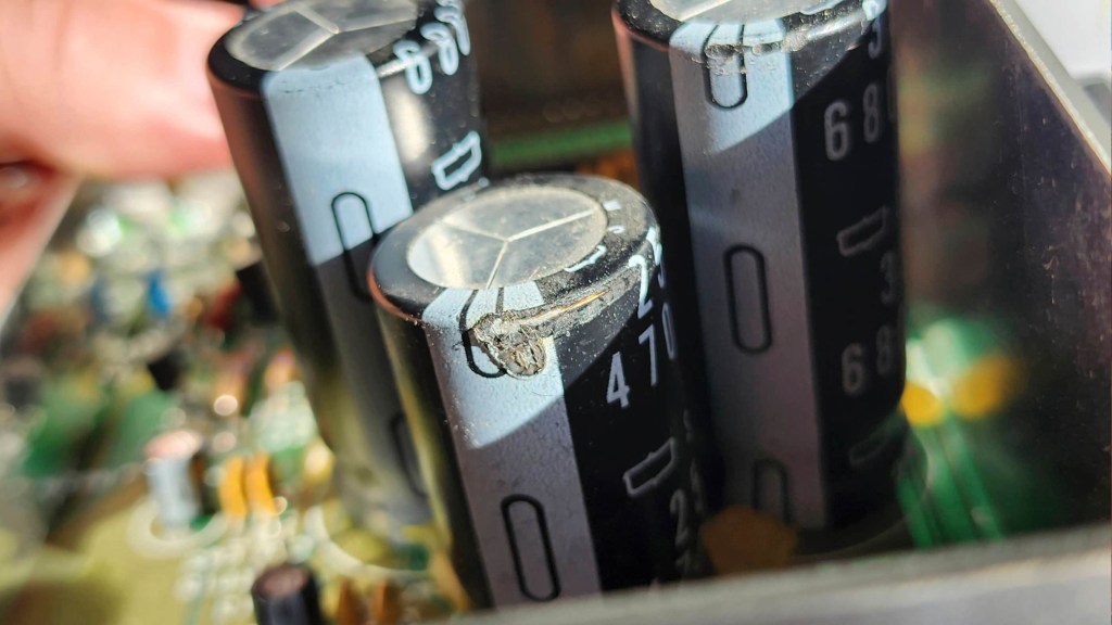
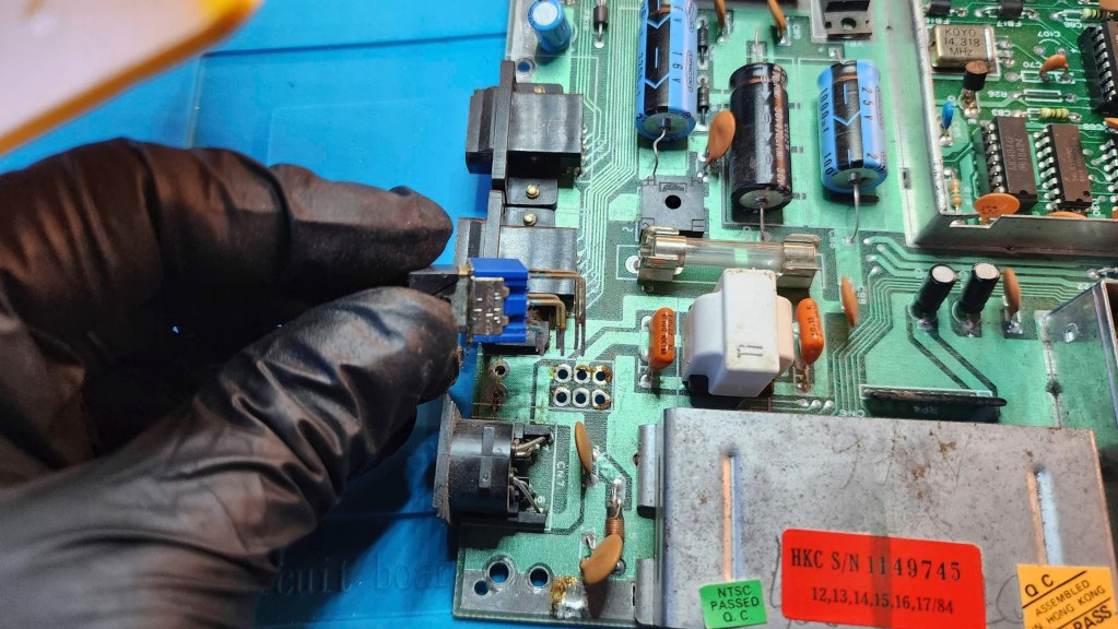
With the computer good to go, I turned my attention to the 1050 5.25” floppy drive. It was in good working condition, but on opening it for cleaning, I immediately noticed that capacitors C67 and C71 had split open at the top. I also noticed that there was corrosion on the power jack. Fortunately, the belt was in good shape.
As I would have to replace C67 and C71, I decided that I’d just replace all the capacitors. I also applied new thermal paste to the voltage regulators and reseated and treated the socketed chips with Deoxit D5. I also removed the corrosion and then cleaned and lubricated the drive mechanism.
Once it was mostly back together, I was able to run it through testing and it all checked out. I reassembled it completely and I now have a great accessory to my rejuvenated 800XL.
Parts & Products Used: 99% isopropyl alcohol; Chemical Guys Natural Shine; Deoxit D5; Alien Tape; thermal paste; 26 gauge wire; Samsung 4164-120 DRAM (8); 100R 5% (1). 1050 5.25″ Floppy Drive electrolytic capacitors (radial): 16v 47μF (4); 25v 4700μF (1); 35v 4.7μF (2); 35v 6800μF (2); 50v 1μF (1); 50v 2.2μF (1).
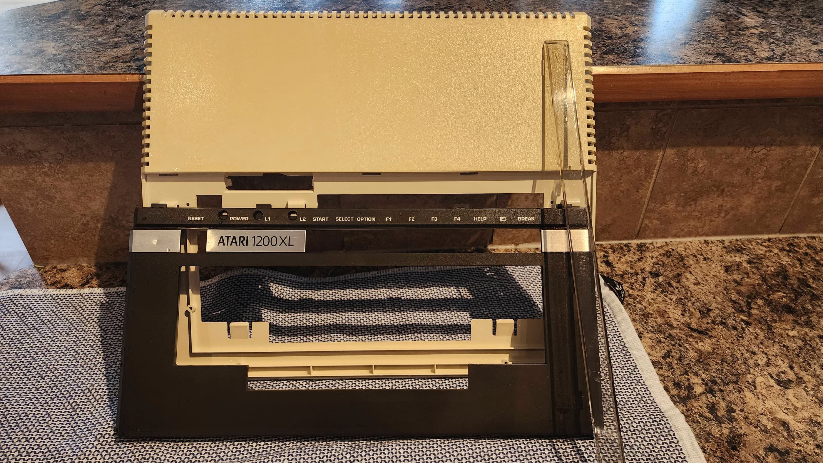
Atari 1200XL
Years (1983)
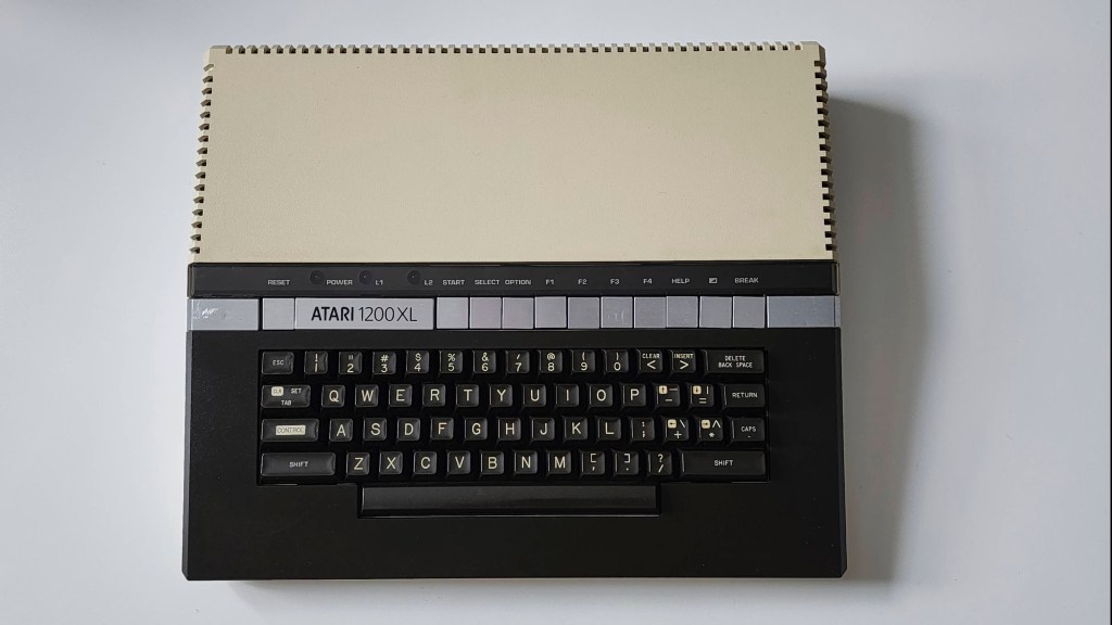
Interesting Fact: Designed to be the replacement for the Atari 400 and 800 computers, the 1200 XL was the only computer produced by Atari’s 1982 Sweet 8 / 16 project team. (source) Though the goal was to create the Atari 1000 (16K) and the Atari 1000-X (64K) as replacements, the team’s ambitious plans were sidelined by cost-cutting measures imposed by management. (source) The result was the 1200 XL which was a hybrid of the two systems but with some of the important upgrades left out. For example, the 1000’s Parallel Bus Interface (PBI) expansion connector was not included, leaving only the SIO port for peripherals. As stated by the Centre for Computing History, “the fact that the +12V pin in the SIO port was left unconnected; only +5V power was available although some devices made use of the +12V line. An improved video circuit provided more chroma for a more colourful image, but the chroma line was not connected to the monitor port, the only place that could make use of it.” (source) It also did not include a ROM for BASIC that meant user’s still had to insert a cartridge to begin programming and coupled with this, there were compatibility issues with some existing 400 / 800 software. (source) The 1200 XL did however, feature 64K and did feature a redesigned case along with internal diagnostic testing.
When it was launched in January 1983, it was billed by Atari as a competitor for the Commodore 64; however, its high price point and that it was functionally the same, as the cheaper Atari 800, hamstrung the 1200 XL even before it hit the shelves. (source) Thus, within eight months after its release, Atari cancelled production of the 1200 XL. (source) With such a limited production time, it has been speculated based on serial numbers that between 105,000 and 110,000 units were produced. (source; source) This makes the 1200 XL a very rare and collectible item.
Condition When Acquired: Non-Functional
Current Condition: Fully Functional
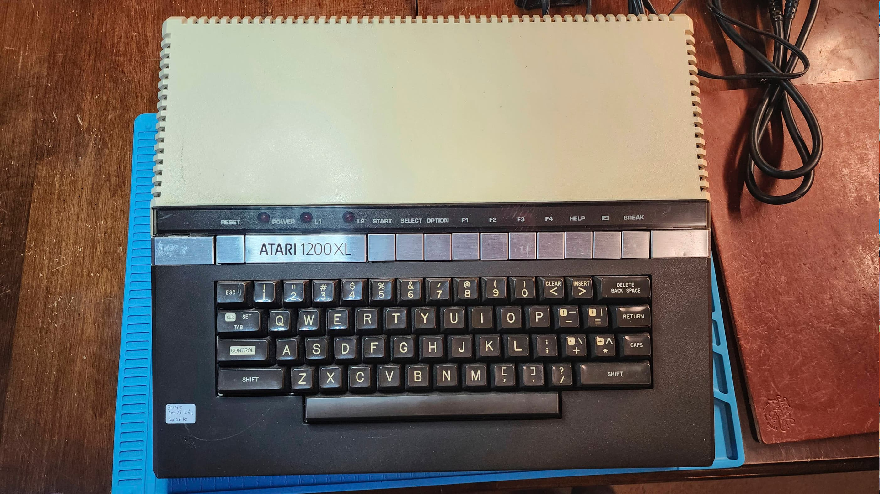


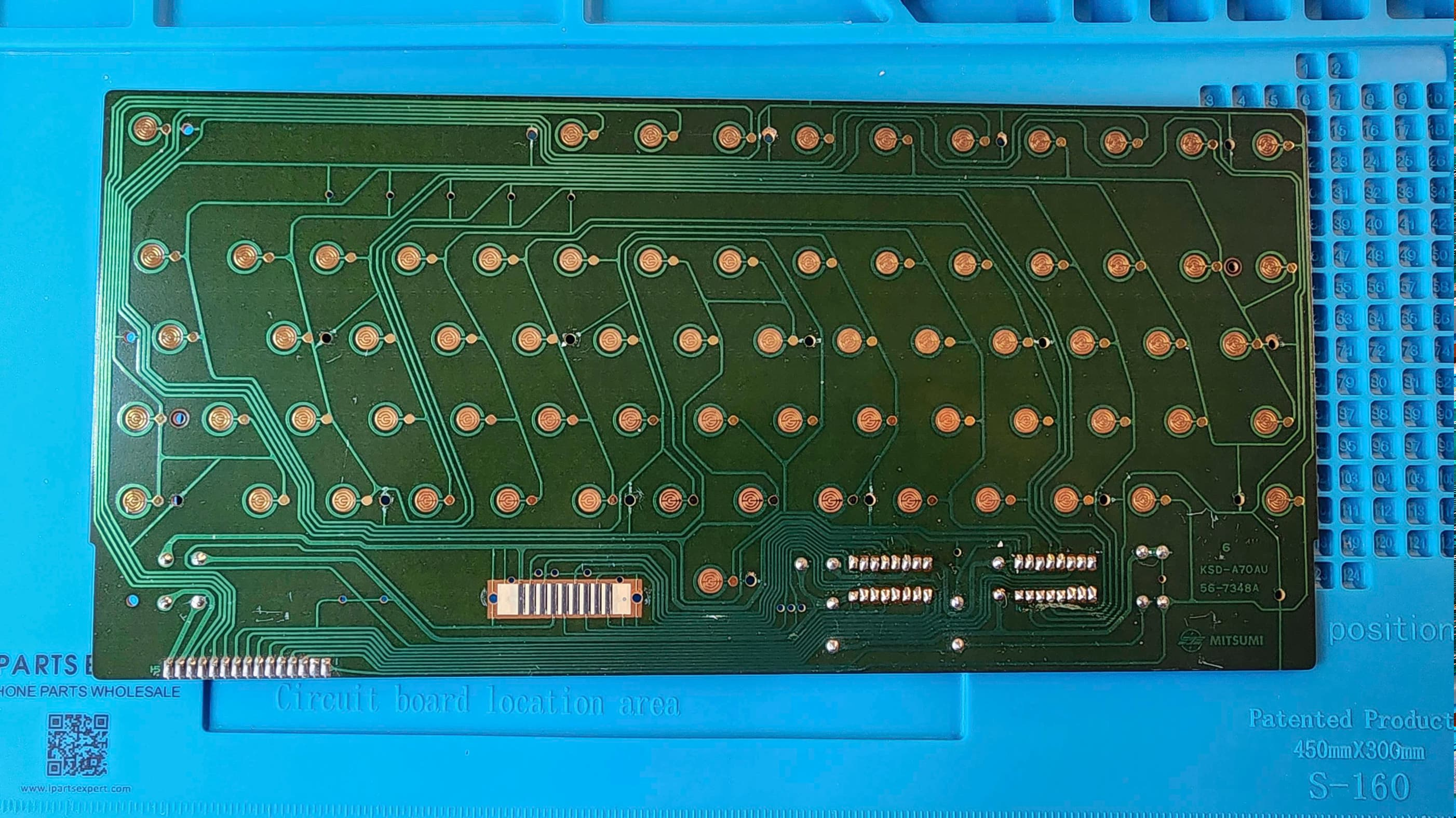
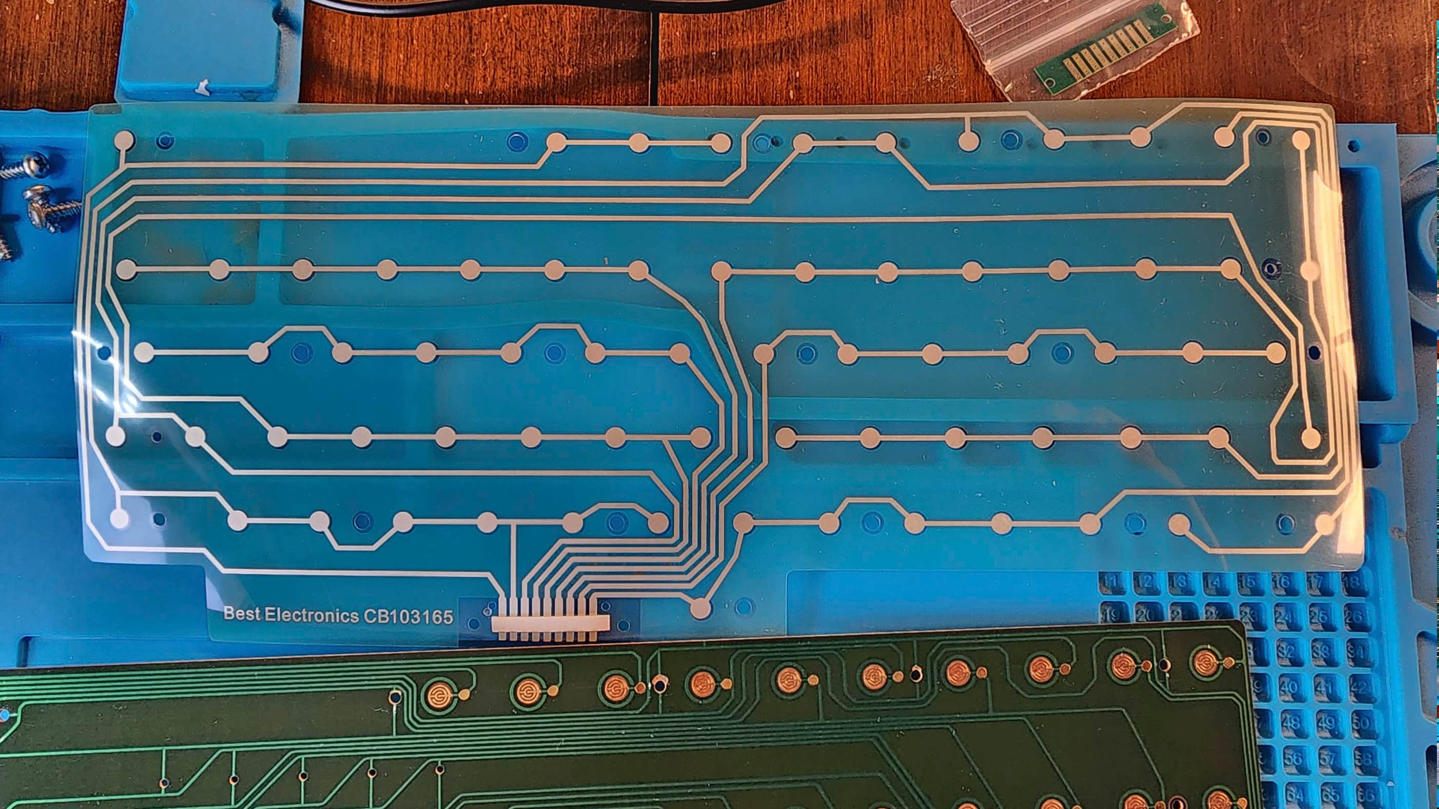
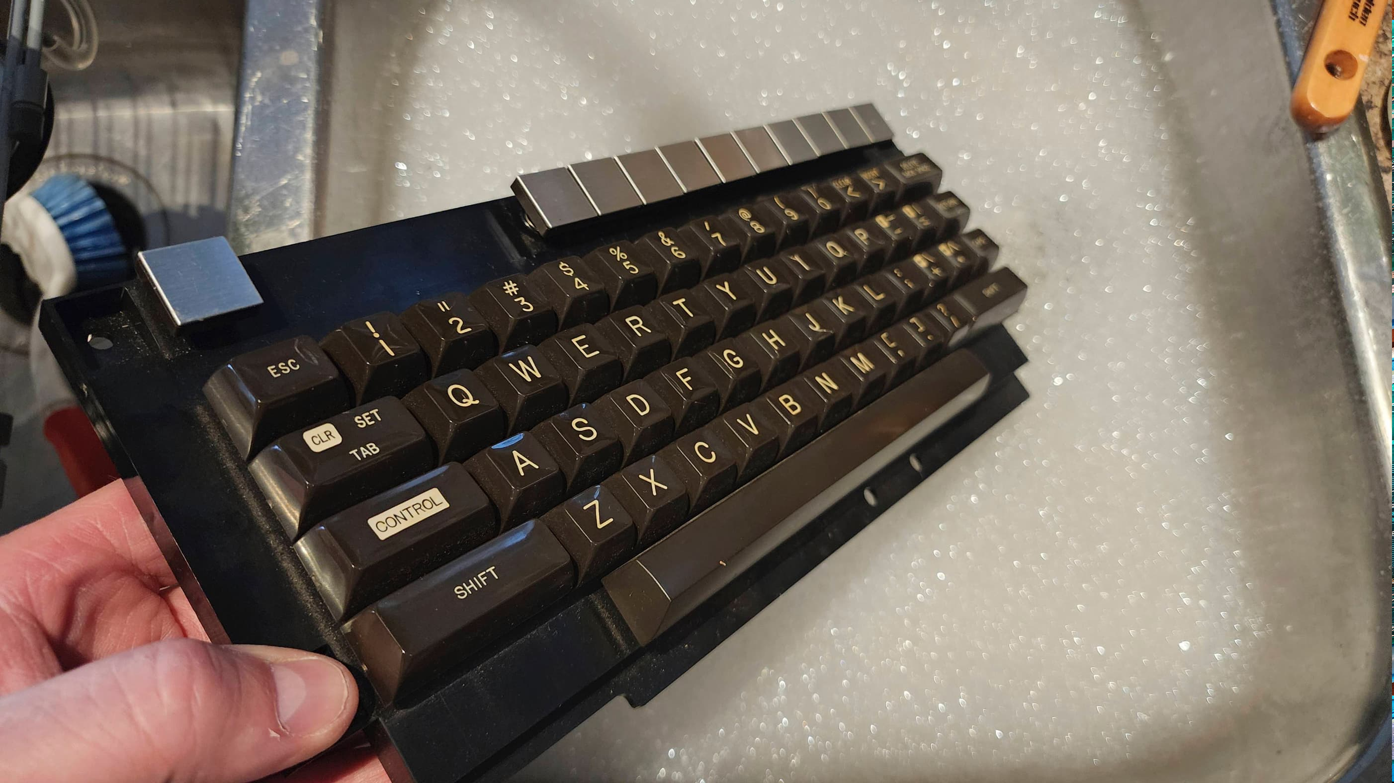


Project Details: I couldn’t believe my eyes when I saw an Atari 1200 XL on Ebay for such an insanely cheap price. The seller in Ontario noted that while it would load cartridges, only a couple keys on the keyboard were functional; making it unusable. I however, knew that the keyboard issue was common to the 1200 XL and that Best Electronics sold a replacement mylar that would hopefully fix this.
After receiving the computer, I did a quick voltage test of the PSU and noted that it produced a healthy and stable 10.94 VDC. Knowing that it was safe to use, I powered on the unit and confirmed that the keyboard was non-functional. I also noted that the display pulsated slightly, which made me think there might be a power issue beyond the adapter.
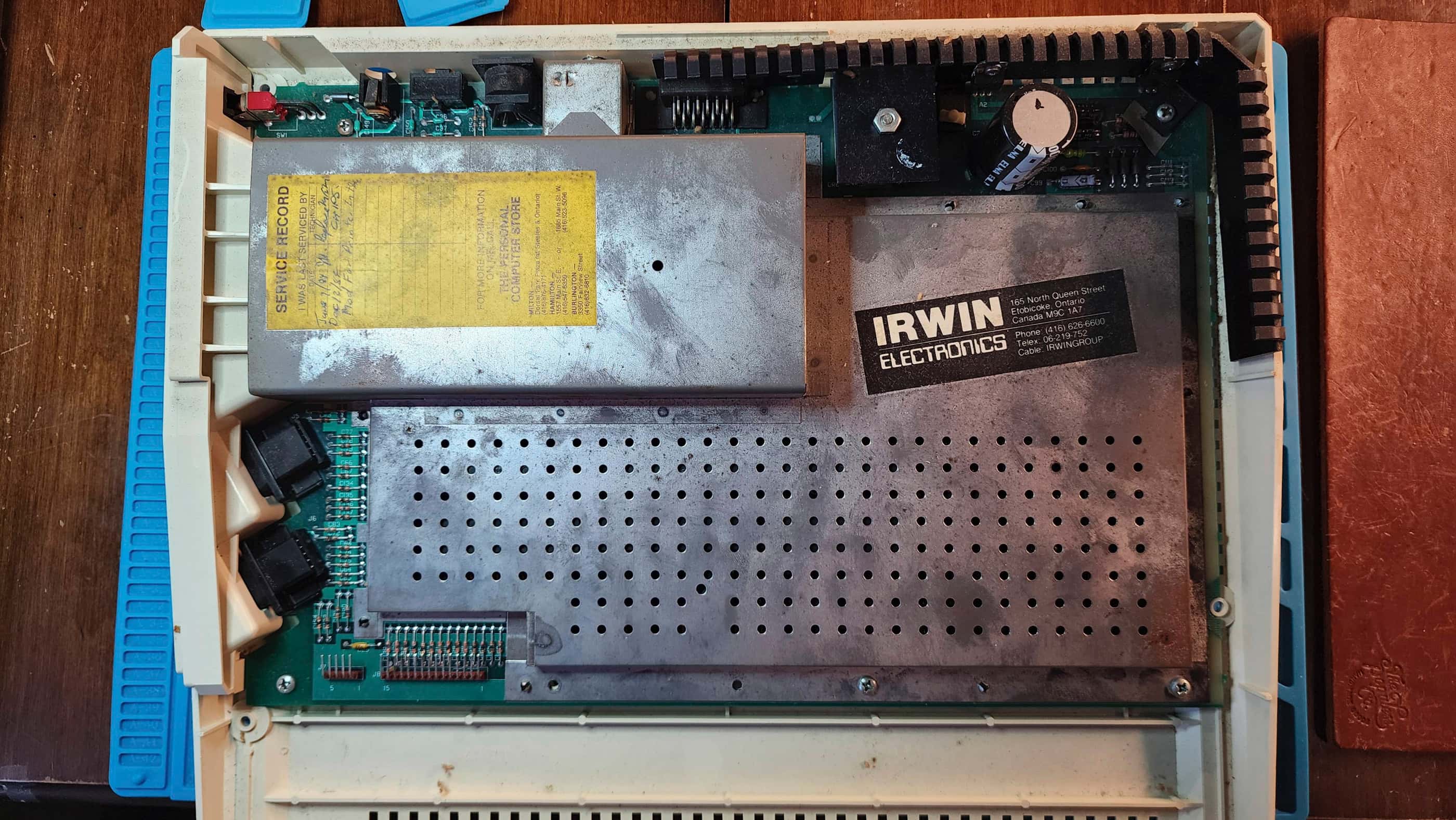
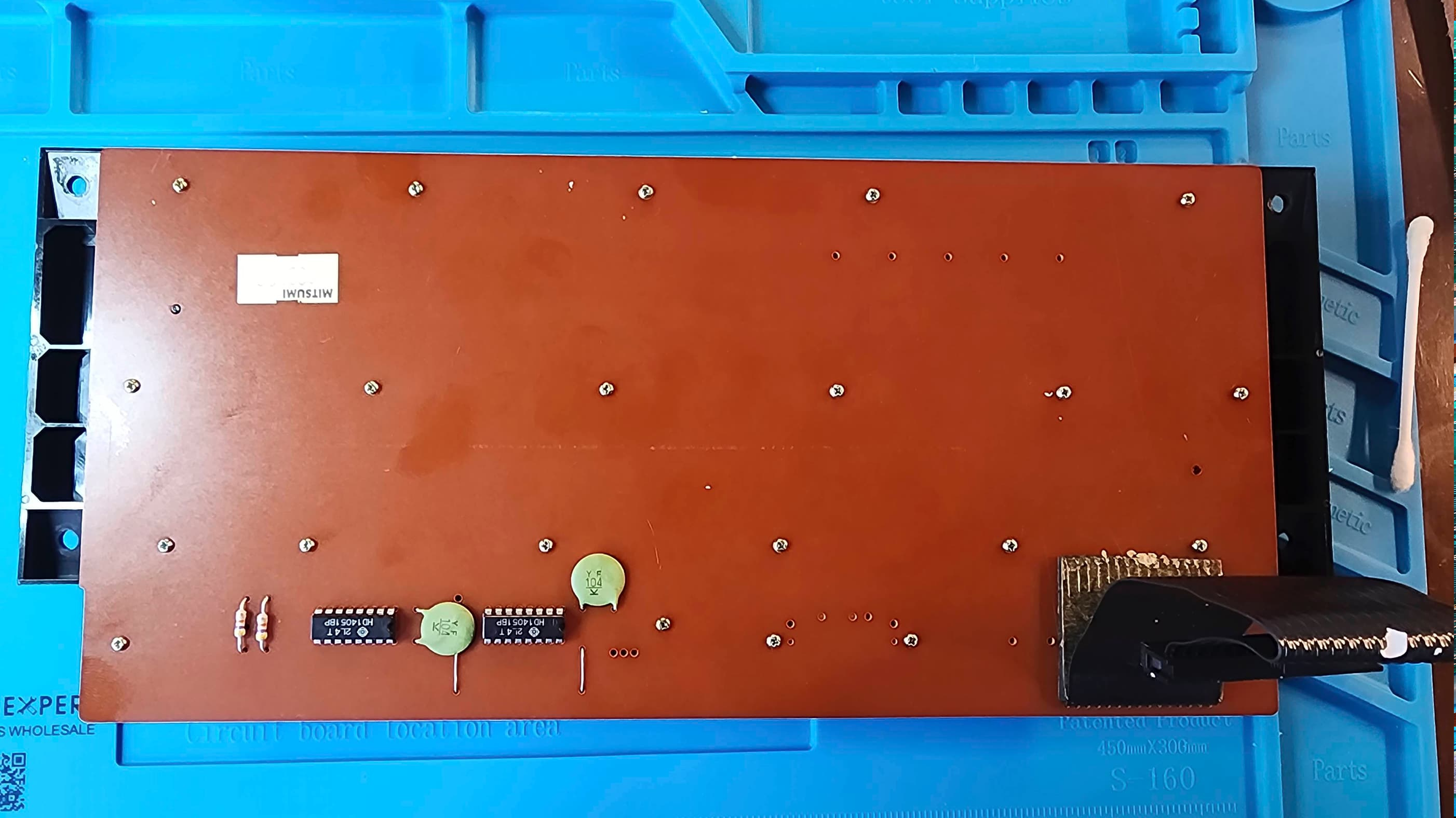
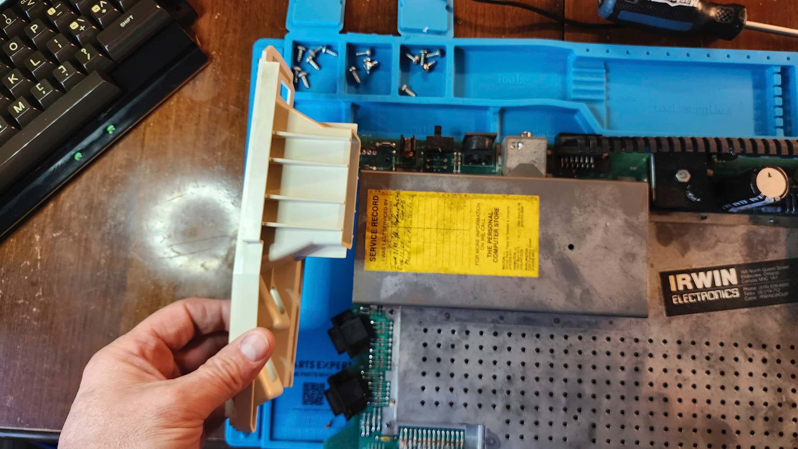
On opening the computer, I was fascinated to see a service sticker on the RF shielding that documented two repairs back in 1984. The first was the replacement of the eight DRAM chips and the second was the “printer mod” which was done to restore the correct voltage to the SIO port so peripherals such as printers could be connected.
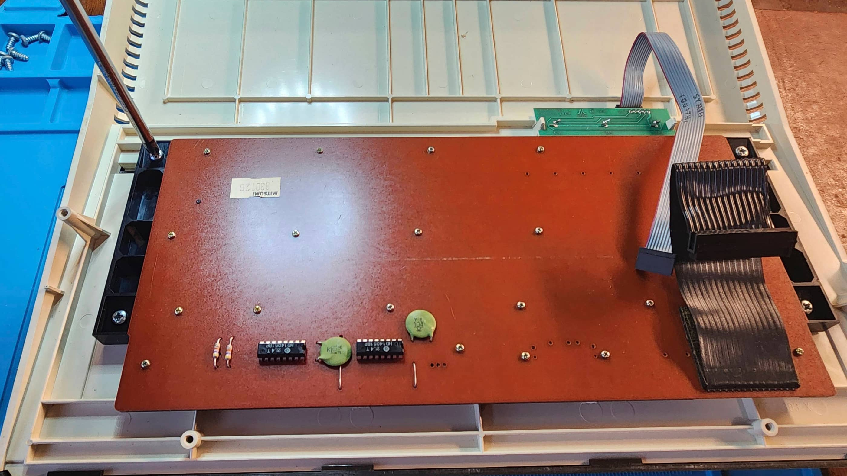
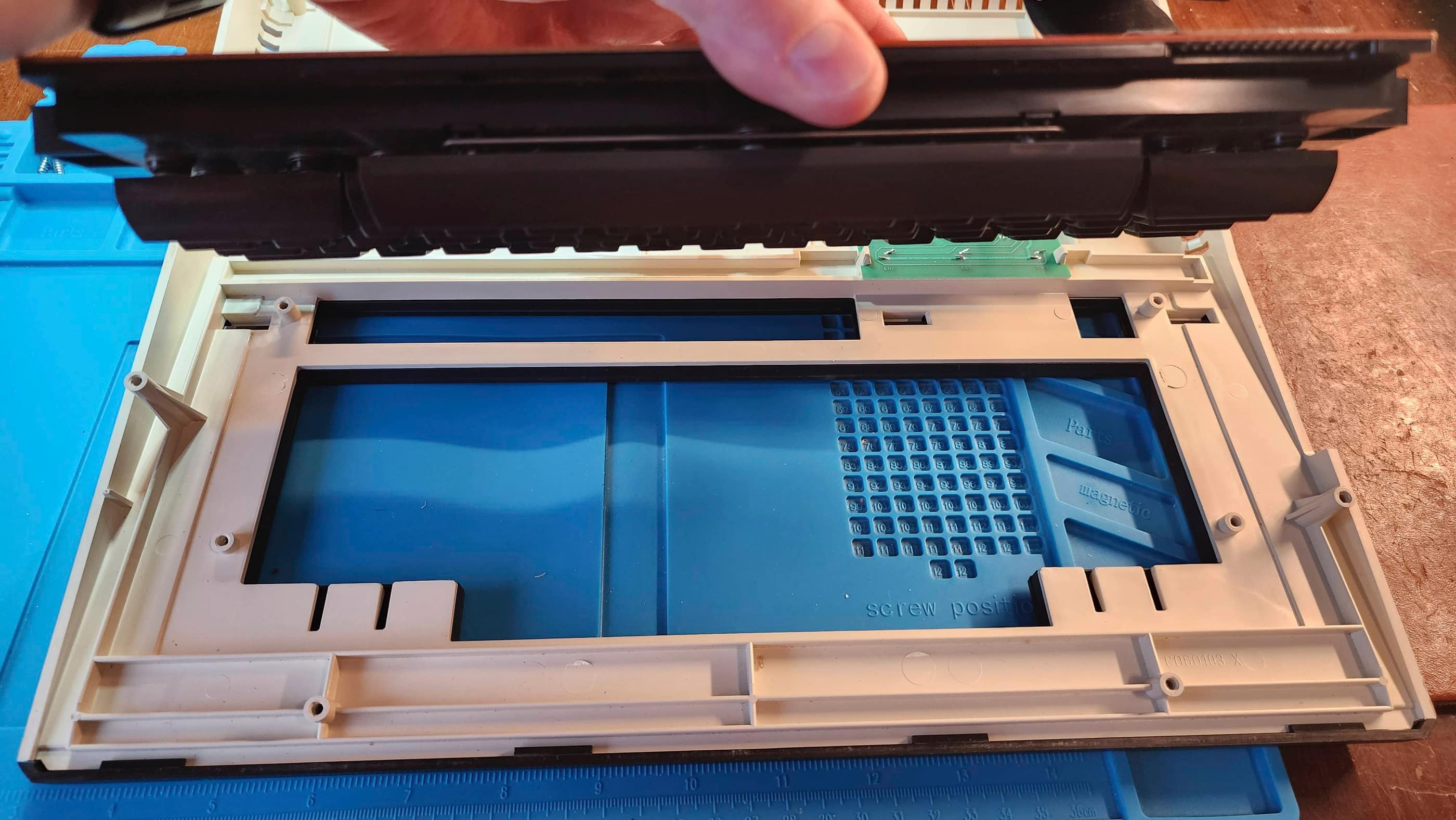
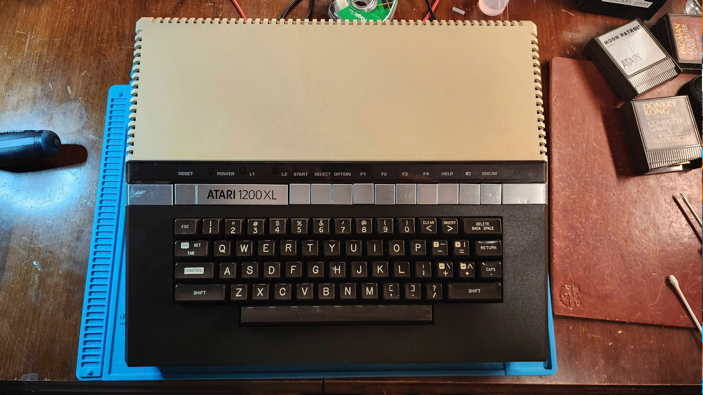
Before I starting anything else, my first priority was to fix the keyboard. So, after removing it from the top case and then unscrewing and removing the PCB from the back of the keyboard, I began to inspect the old mylar. Following the detailed instructions provided by Best Electronics along with supplemental information from FlashJazzCat, I proceeded very carefully, using my hot air tool set to 100 C while slowly lifting the old mylar off the PCB beginning with the edges. Since I wanted to preserve the old mylar just in case, it took me over an hour to get the PCB fully exposed and cleaned.
Installing the Best replacement mylar was incredibly simple and once complete, I restarted the computer to test it out. Using the built-in diagnostic test, I tried every key and confirmed all of them to be in working order. With the keyboard now fixed, I moved on to explore the pulsating video issue.
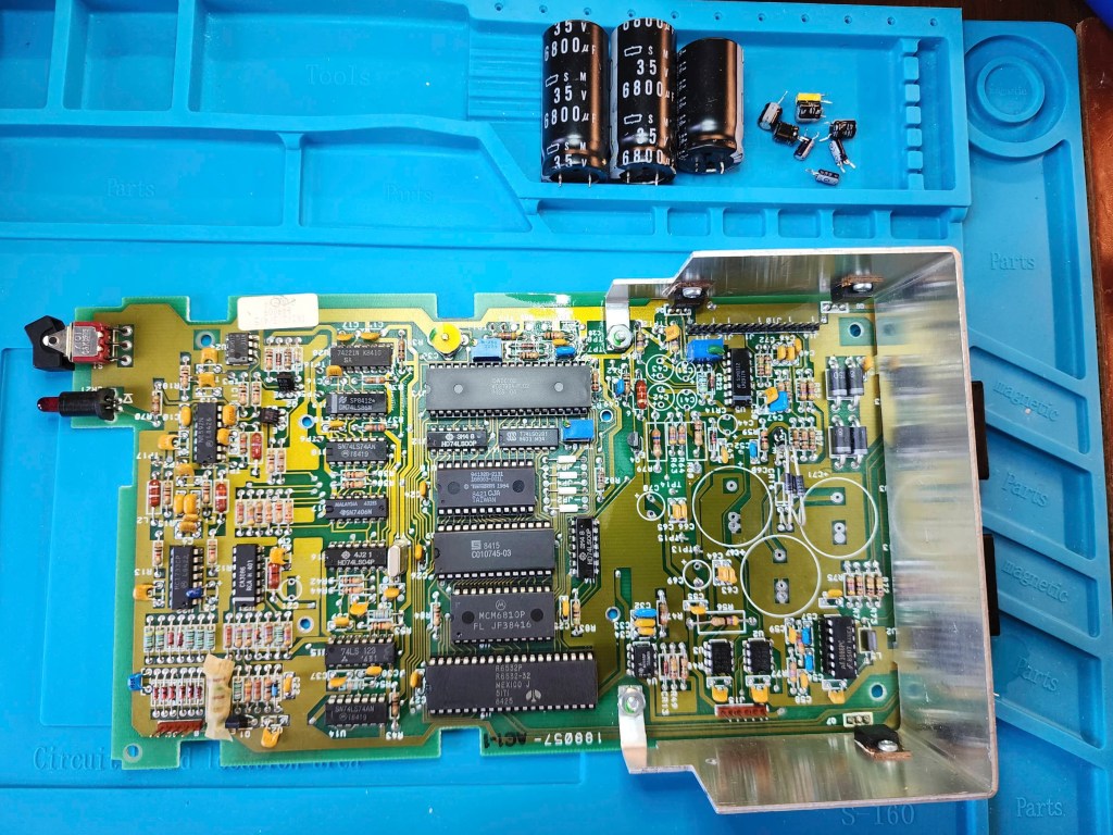
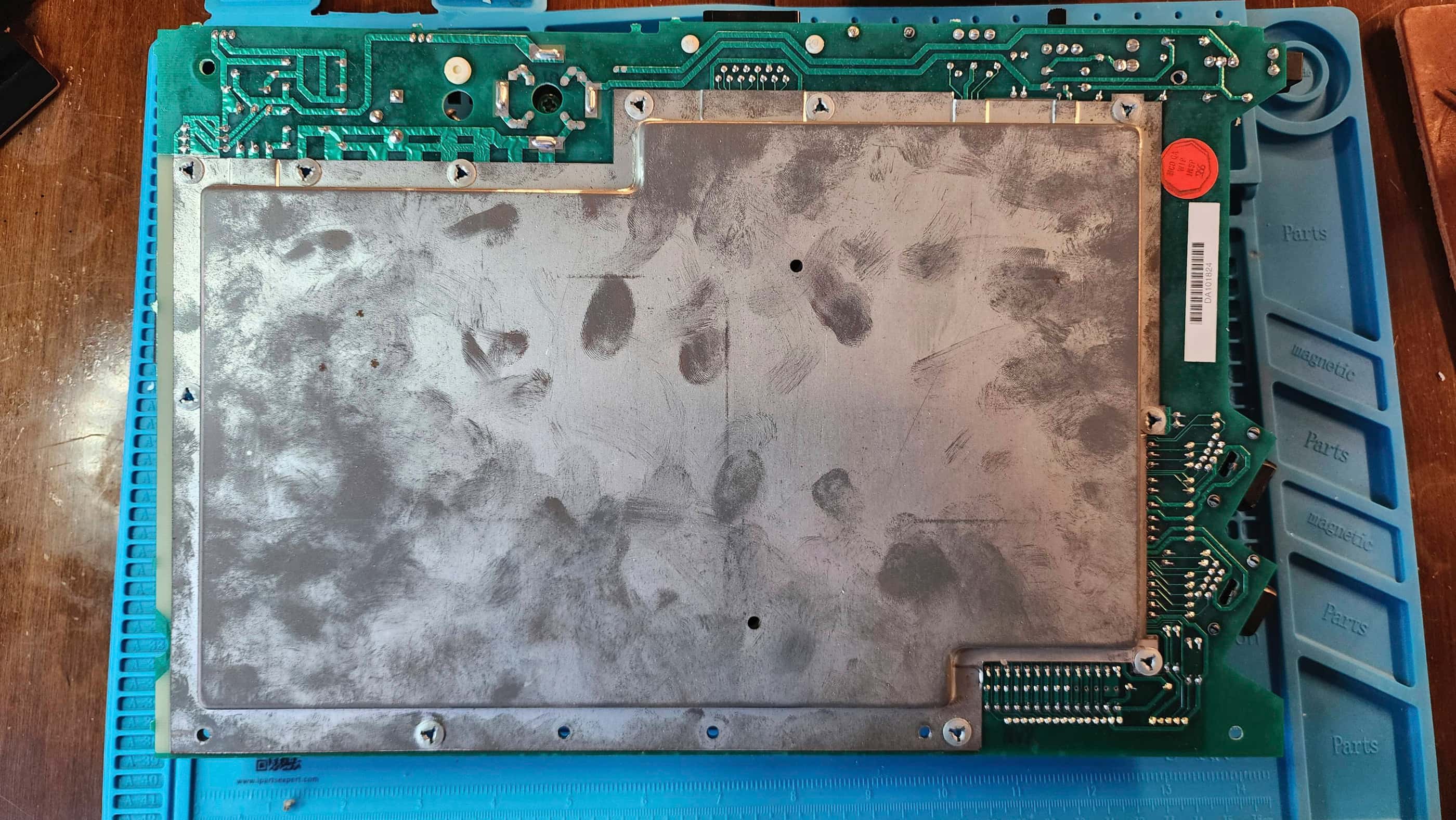
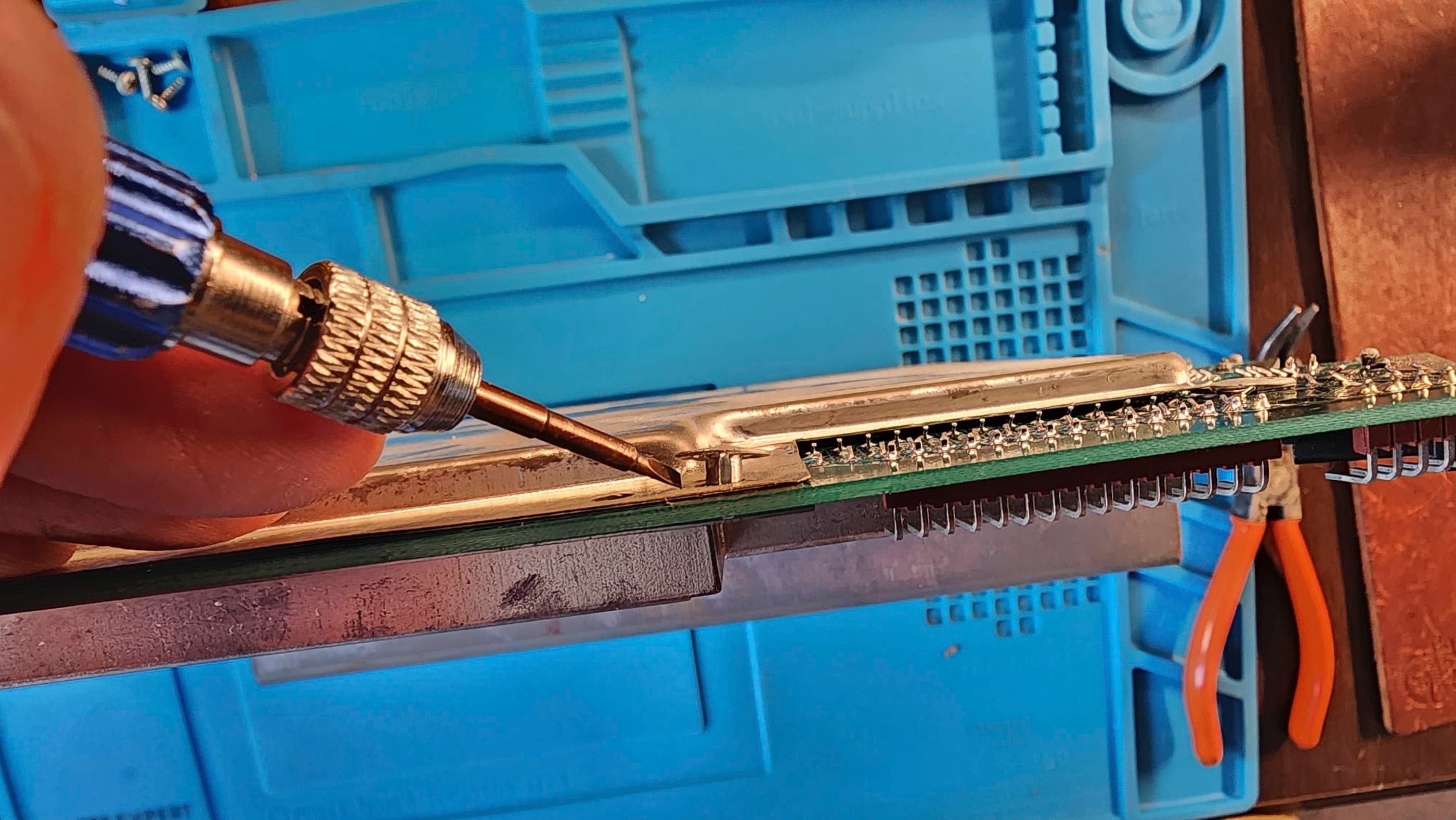
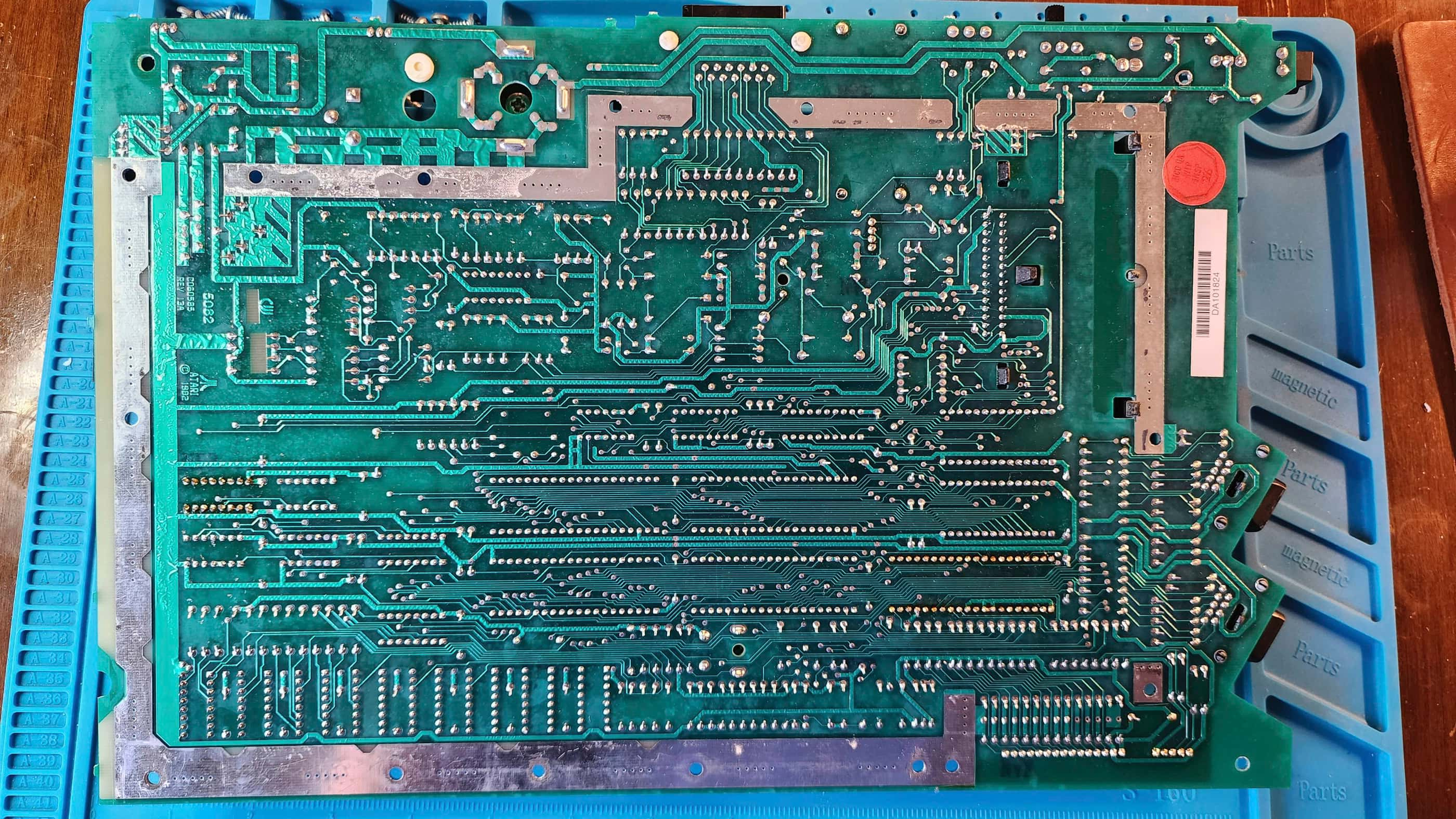
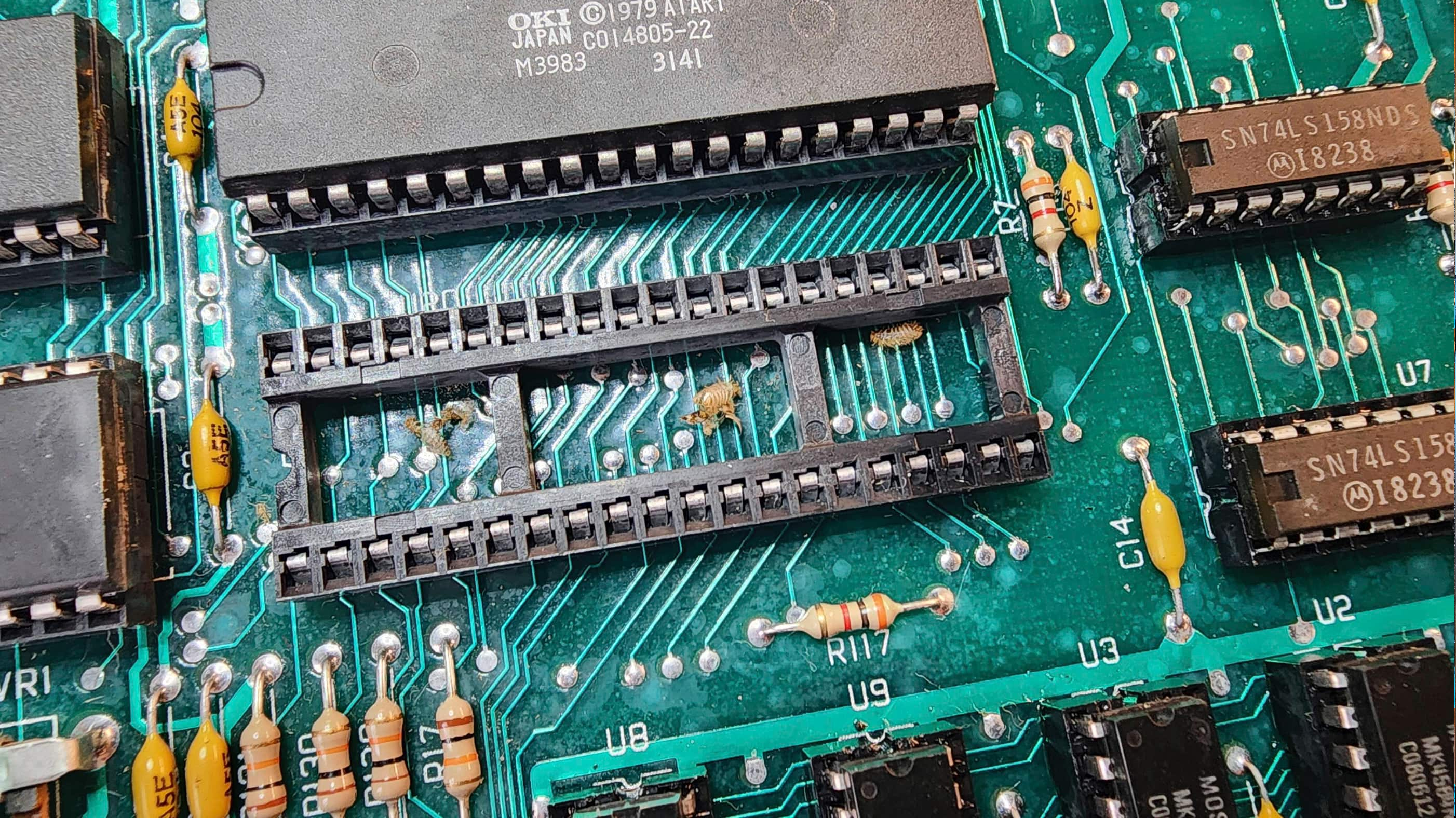
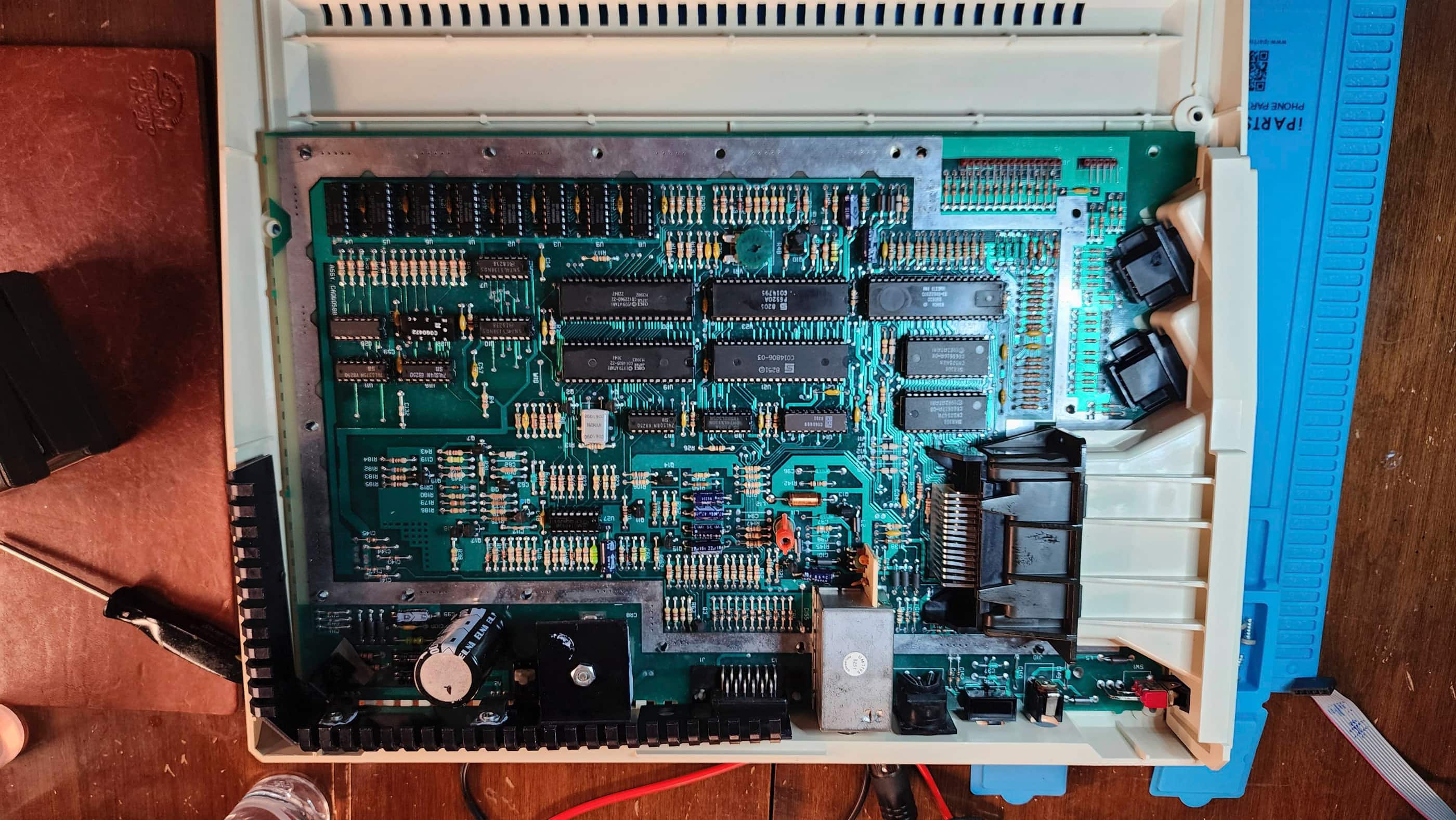
Removing the RF shielding was an interesting experience, as it used push-through rivets to hold it in place instead of screws and/or folding tabs. After removing the shielding, I quickly noted that the board was full of insect exoskeletons. Yuck! Wherever it had been stored in the past, it was obviously a favourite for the resident insect population. So, before going further into my inspection, I spent time vacuuming out the dust and exoskeletons.
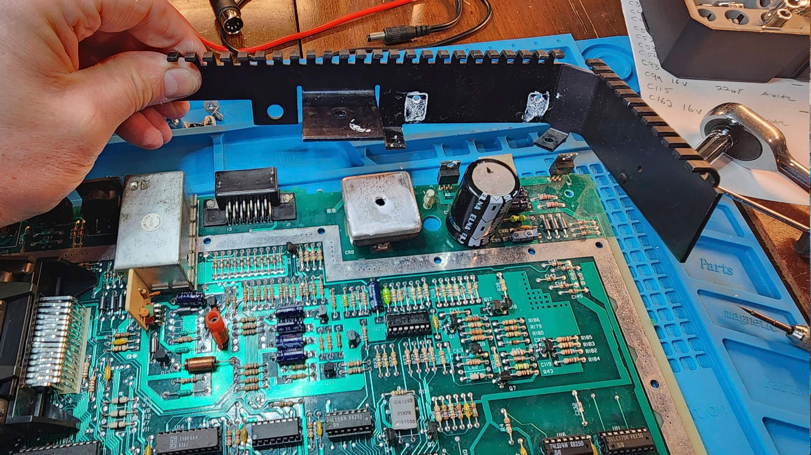
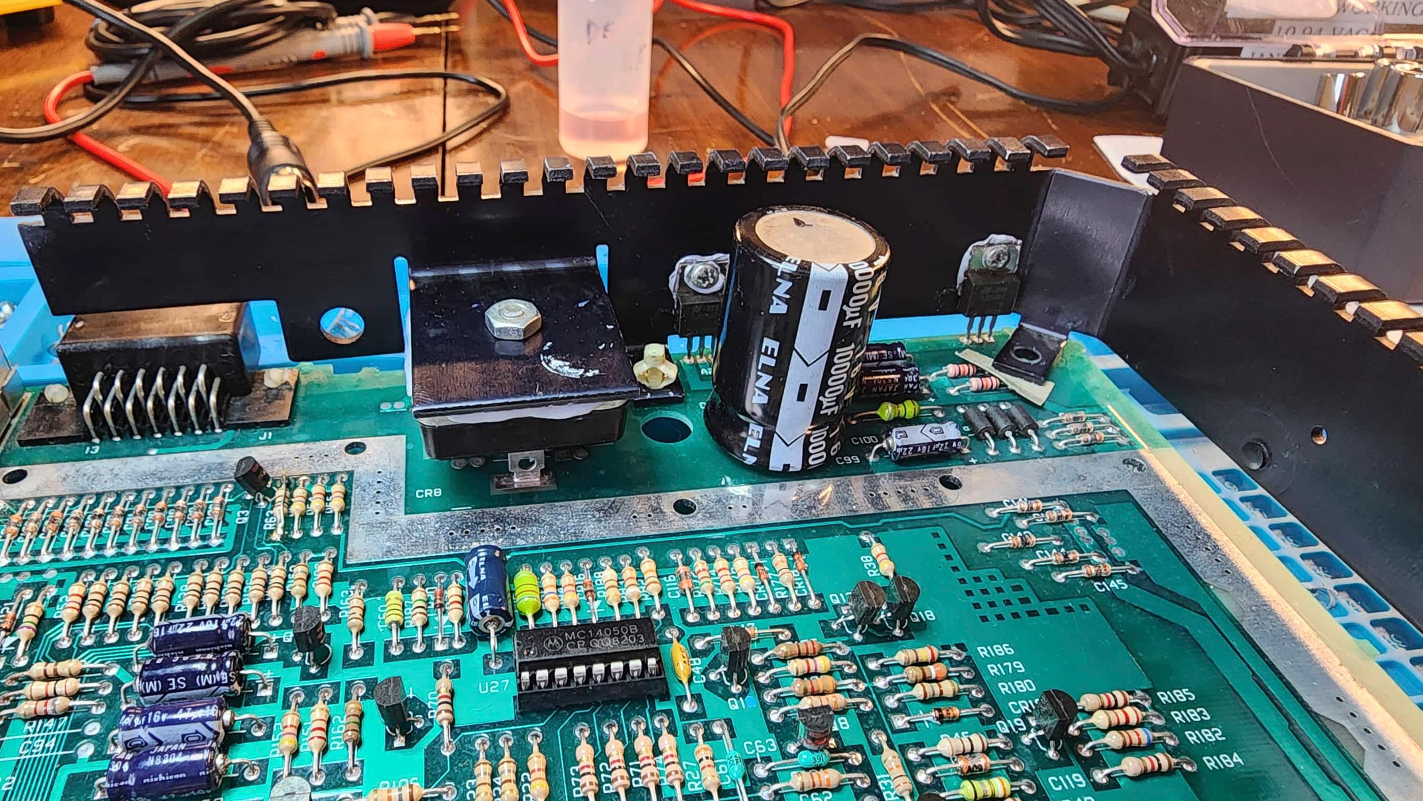
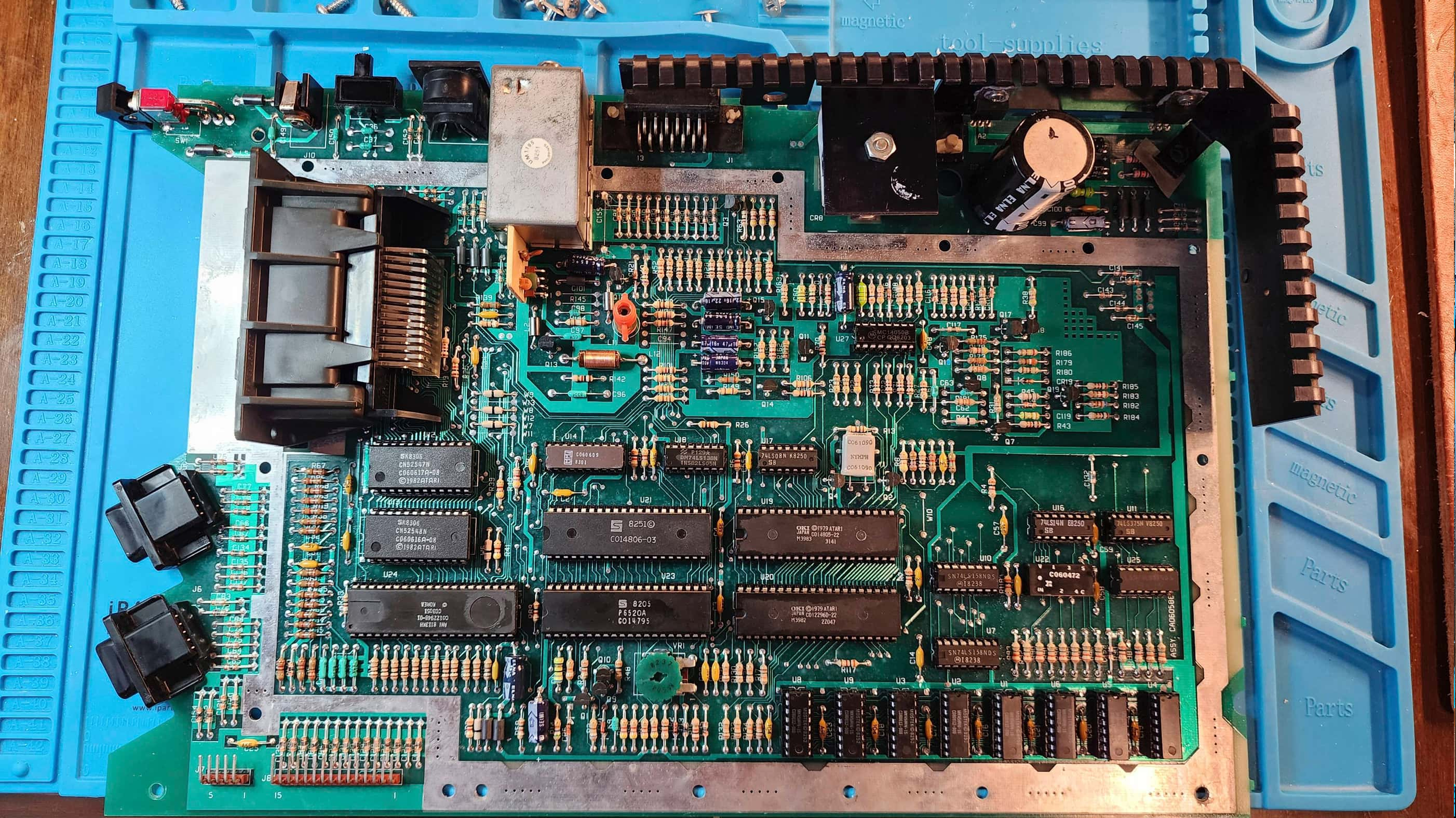
With bugs no longer an issue, I began to closely examine the board. It was fascinating to see that the Atari engineers used a massive rectifier to convert the 9 VAC from the PSU to 12 VDC followed by two 7805 regulators to convert the 12 VDC to 5 VDC. To compensate for the heat produced, the rectifier and the regulators are affixed to a massive heatsink that wraps around the top right side of the board. Weird, but it makes sense if the design kept being changed during production.
Anyway, I did see that the PSU jack on the board was heavily oxidized, and so I treated it with Deoxit D5 and gave it good scrubbing. I then powered the unit back on and noted that the display was stable and not pulsating, so this was good news.
I could also see the “printer mod” that was done in 1984 by the service tech. This involved the very simple process of running a bypass wire on R63. I then spent a considerable amount of time debating whether I should perform Bob Woolley’s ClearPic mod to improve the 1200’s notably poor video output. After watching FlashJazzCat’s video I concluded that it was indeed a very easy mod; however, as 1200s are such rare items, I decided that I wanted to keep this unit as close to stock as possible to preserve its history.
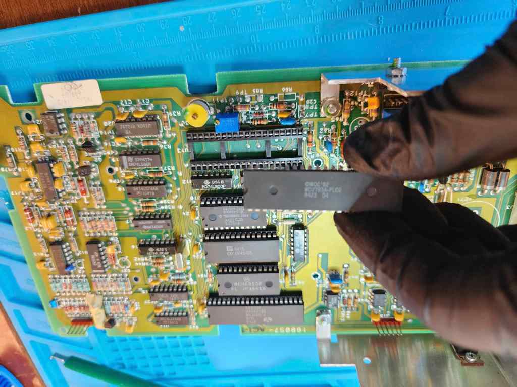
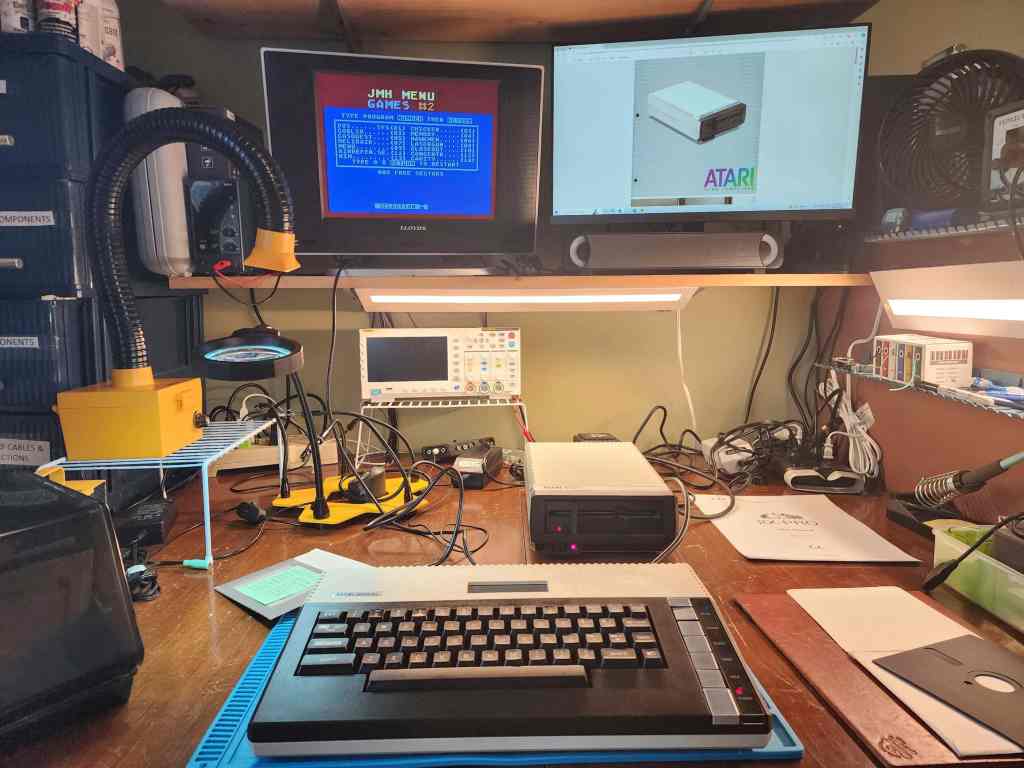
I then reseated and treated all socketed chips with Deoxit D5 and removed and reapplied new thermal grease to the rectifier and voltage regulators. Next, I gave everything a very thorough cleaning before reassembling. Once assembled, I ran another internal diagnostic test to verify everything was working followed by inserting and playing several different game cartridges.
I feel very privileged to own a working 1200 XL as these are not easy to come by.
Parts & Products Used: 99% isopropyl alcohol; Chemical Guys Natural Shine; Deoxit D5; thermal paste; Best Electronics Atari 1200XL Keyboard Mylar;
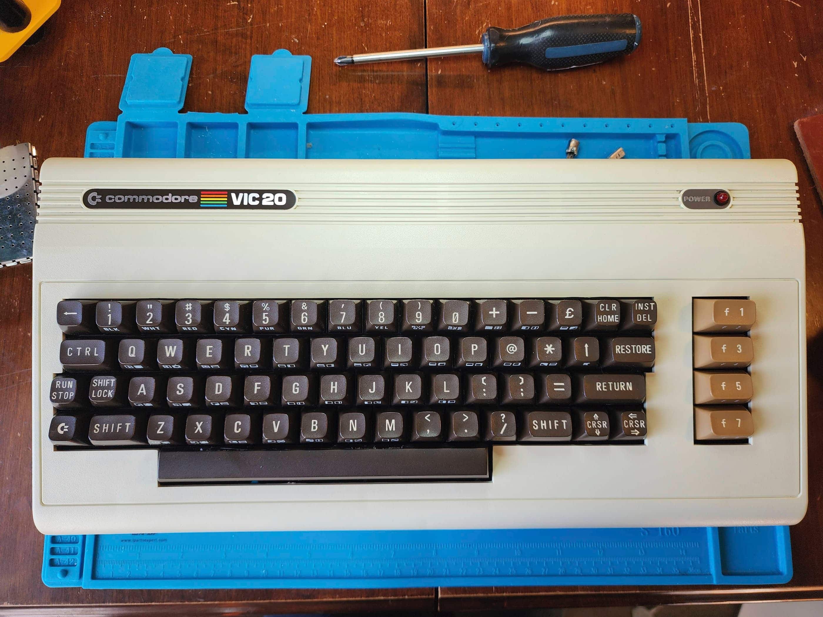
Commodore VIC 20
Years (1980 Japan & 1981 international – 1985)
Interesting Fact: The VIC 20 was the result of Commodore founder, Jack Tramiel’s decision to push the company into filling a gap in the early home computing market. (source) His famous quote, “The Japanese are coming, so we will become the Japanese”, was amplified as his fist pounded the table while he argued with Commodore’s senior leadership, that it was now or never if they wanted to be the first to create and introduce a colour computer for under $300 to the home market. (source) His determination paid off as the VIC20 became the first computer to sell over 1 million units, with production reaching 9000 units per day and $305 million in revenue. (source) According to Commodore’s Michael Tomczyk, the goal was to create a friendly image of a computer for the home buying public, and the name, VIC 20, comes from the proprietary Video Interface Chip combined with ‘20’ because it sounded friendlier than the proposed ‘22’ after its 22 columns. (source)
For a detailed insight into Jack Tremiel and the founding of Commodore, watch the documentary, The Commodore Story by Steven Fletcher.
Condition When Acquired: Partially Functional
Current Condition: Fully Functional


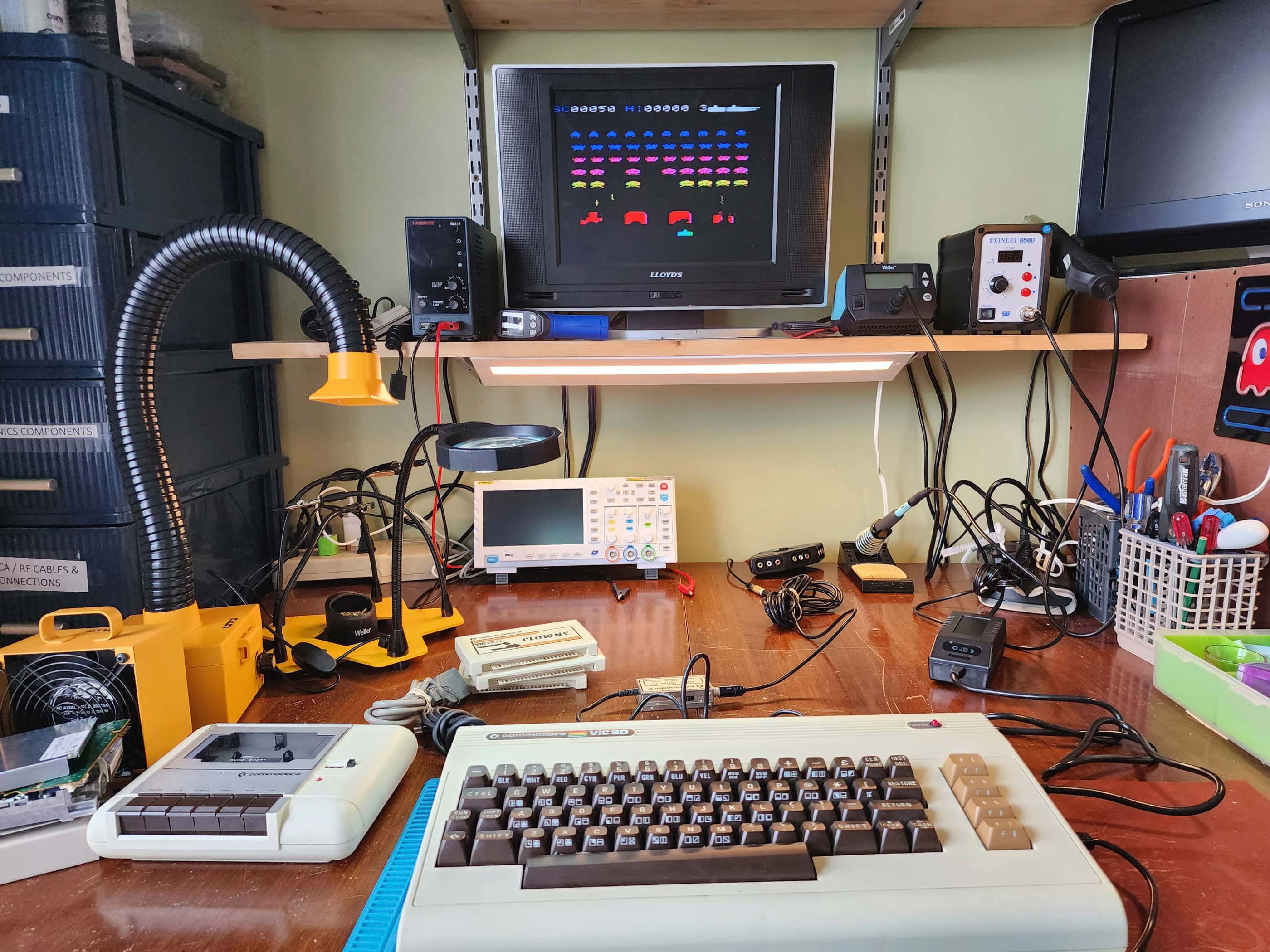


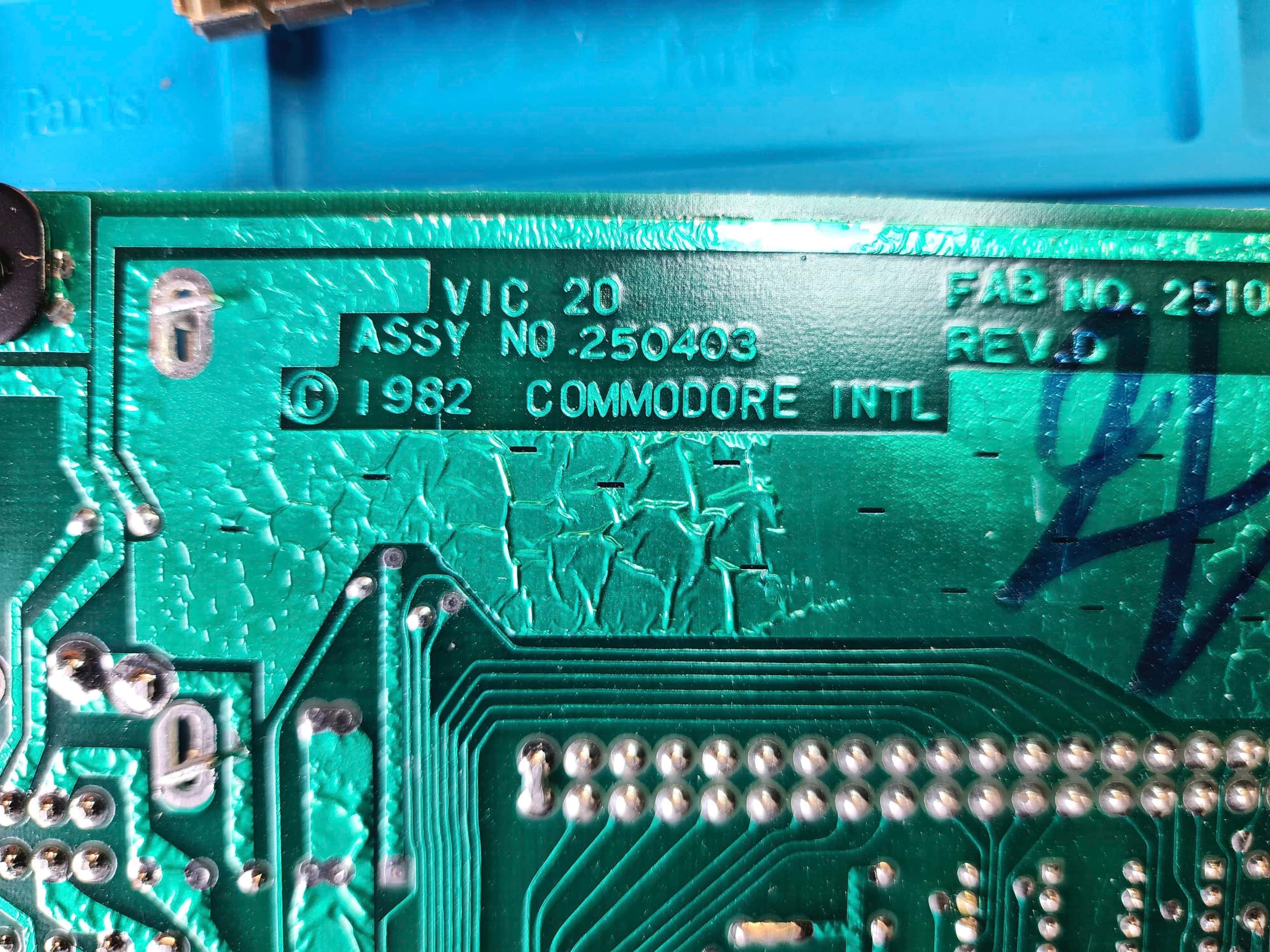


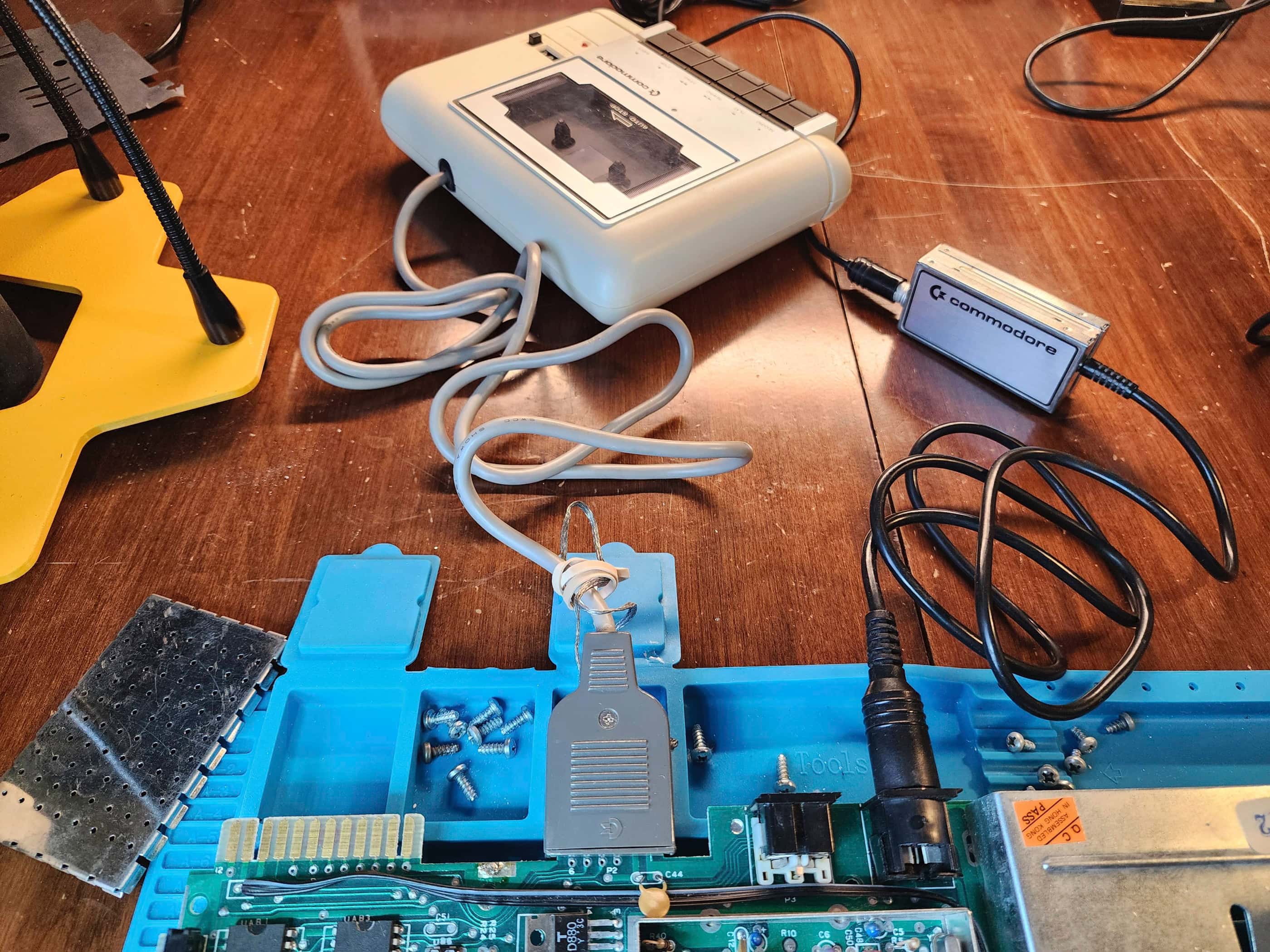


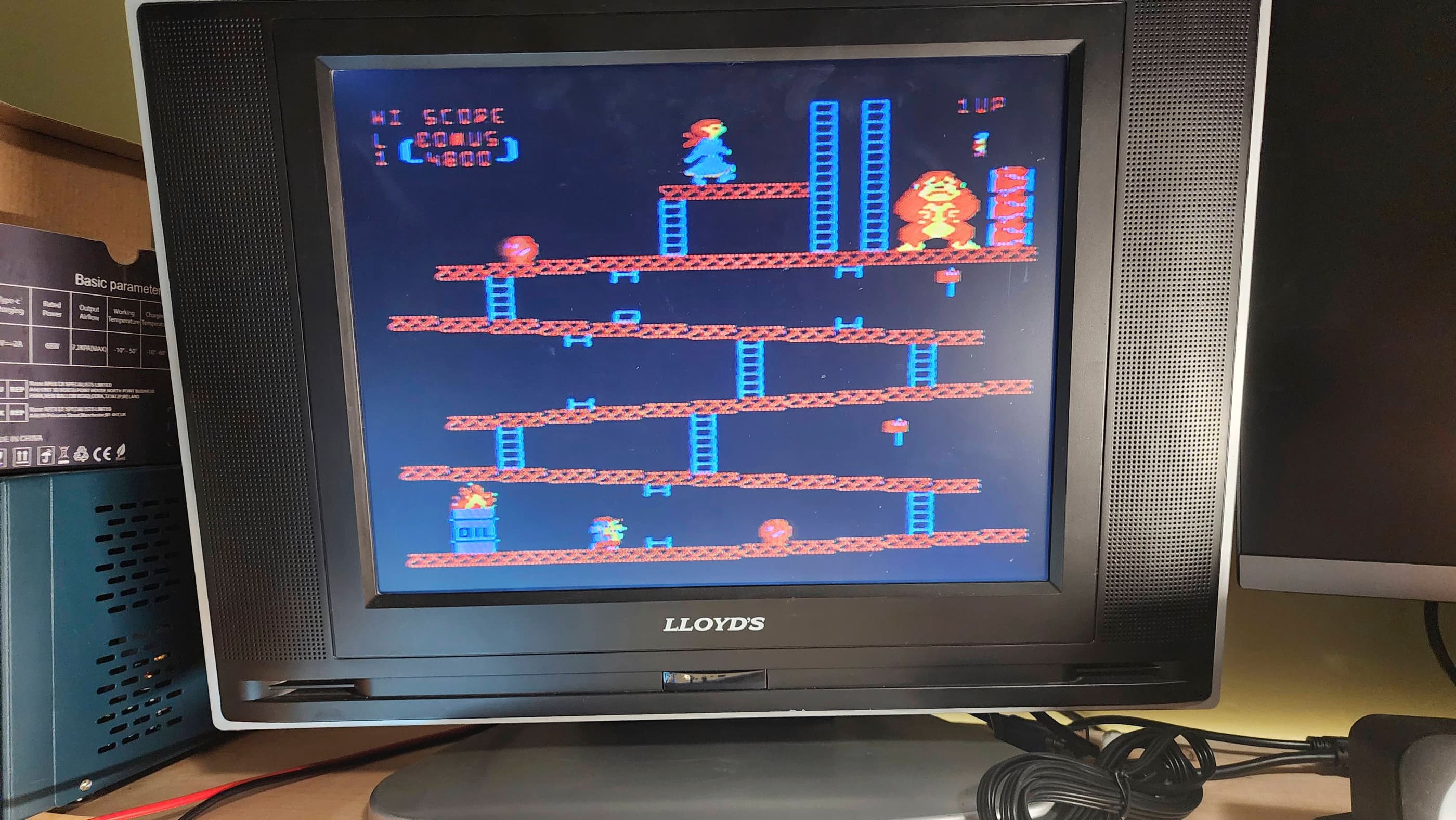
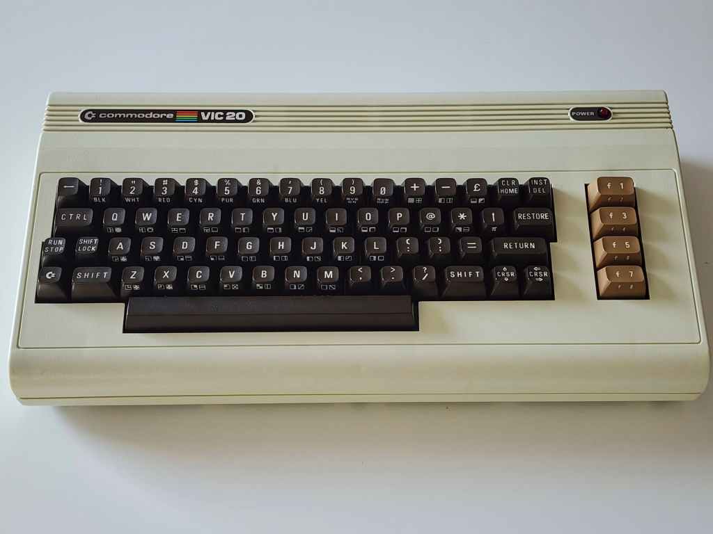
Project Details: This unit was a spectacularly priced, pawn shop find that came in the original box that included the original documentation, 4 games, and the Datasette. 🙂 Though it’s the later, Cost Reduced (CR) version of VIC 20, it still harkens back to the original version of the VIC 20 that was released in North America in 1981.
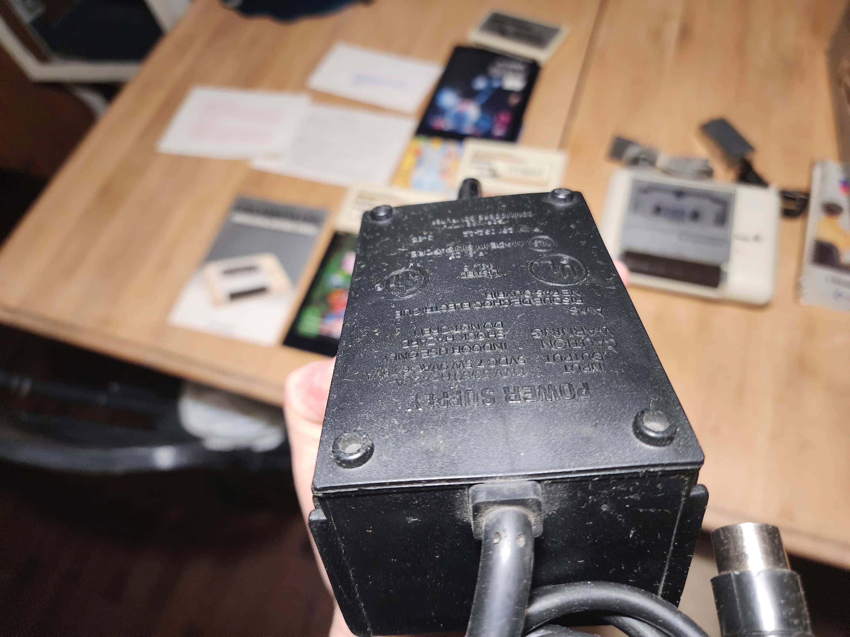
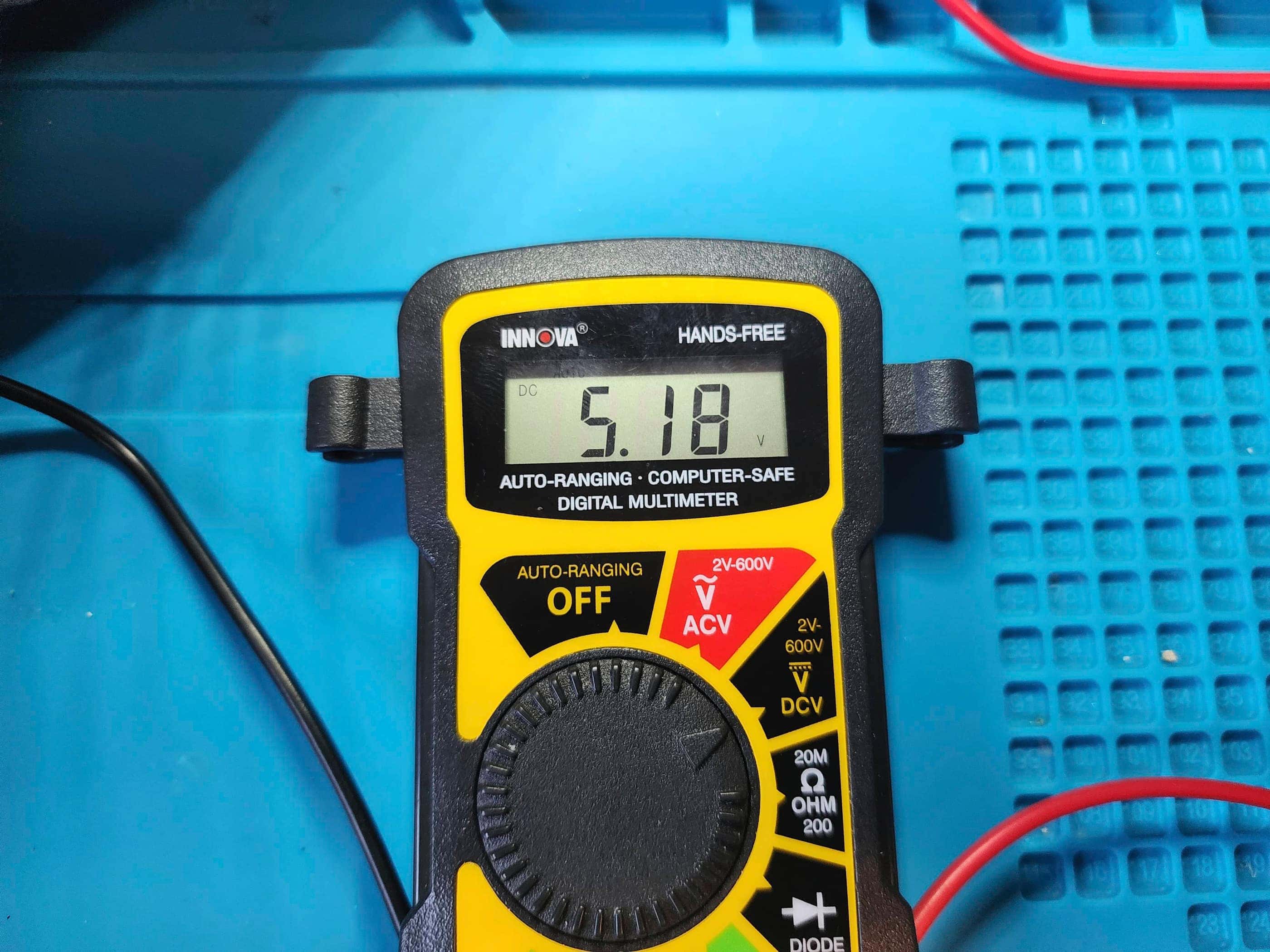
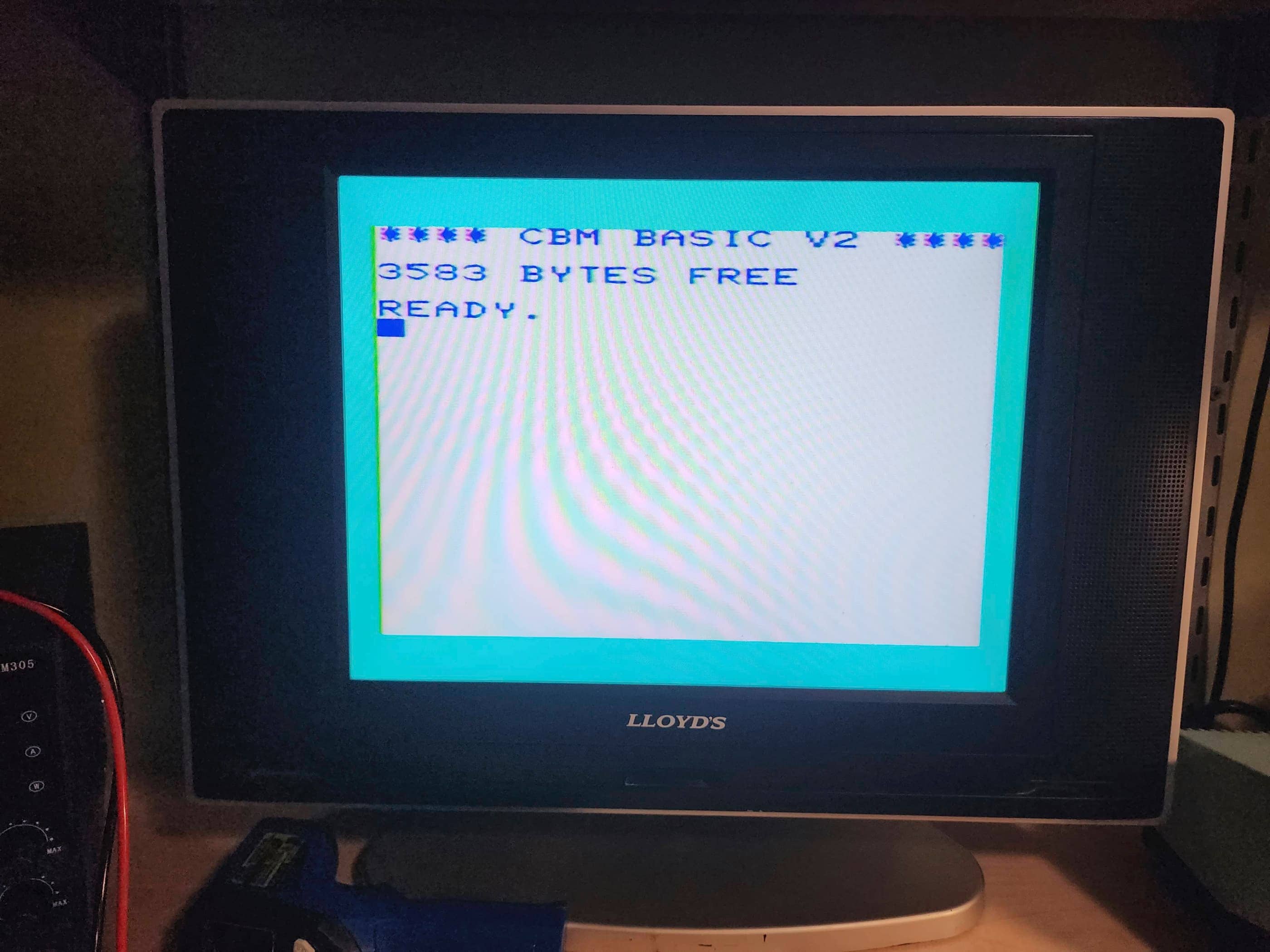
Before powering on the unit, I voltage tested the OEM power supply after noting a large bulge at the bottom of the casing. With the supply registering outputs of 5 VDC of the required 5 VDC but only 5.1 VAC of the required 7 VAC, I knew it was on the way out. However, as I wasn’t going to hook up the Datasette or my 1541 5.25 floppy drive, the AC voltage would not be needed to perform a simple test of the system. So, I proceeded to hook up the unit and power it on… success! It worked! 🙂
This was fantastic news, though I noted that the proprietary 5 pin DIN to RF modulator for video and sound output was wonky. I could get the main screen to display, but there was definite audio static and ghosting graphics. That the keyboard worked and the game cartridges also worked was a huge bonus. All in all, it looked like I’d stumbled onto a machine that was in fantastic shape minus the RF modulator.
However, before going further, I got sidetracked with my brother-in-law’s Amiga 1200 and when I ended up having to order a new power supply from Keelog for that project, I also ordered one for the VIC20. Once that arrived and I had finished the A1200, I got started on restoring the VIC 20.
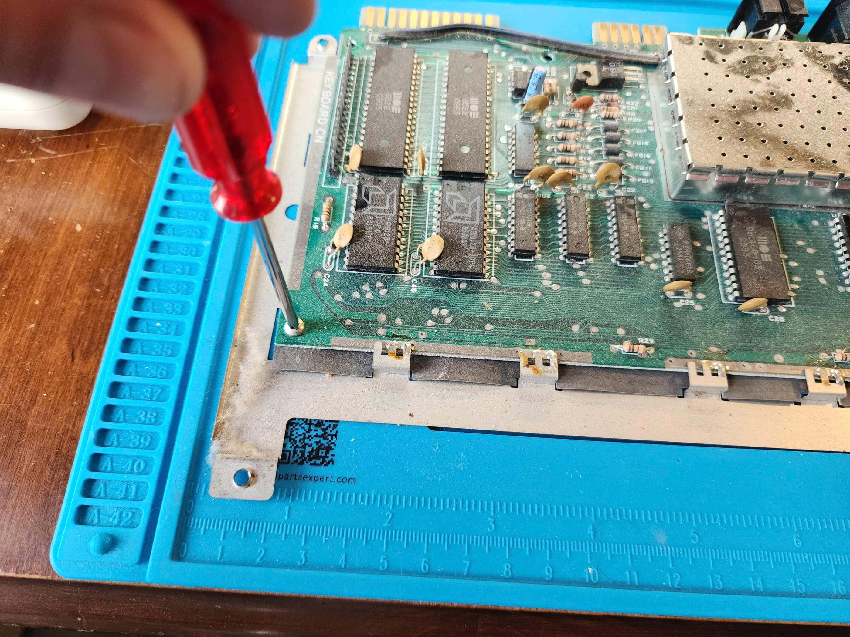
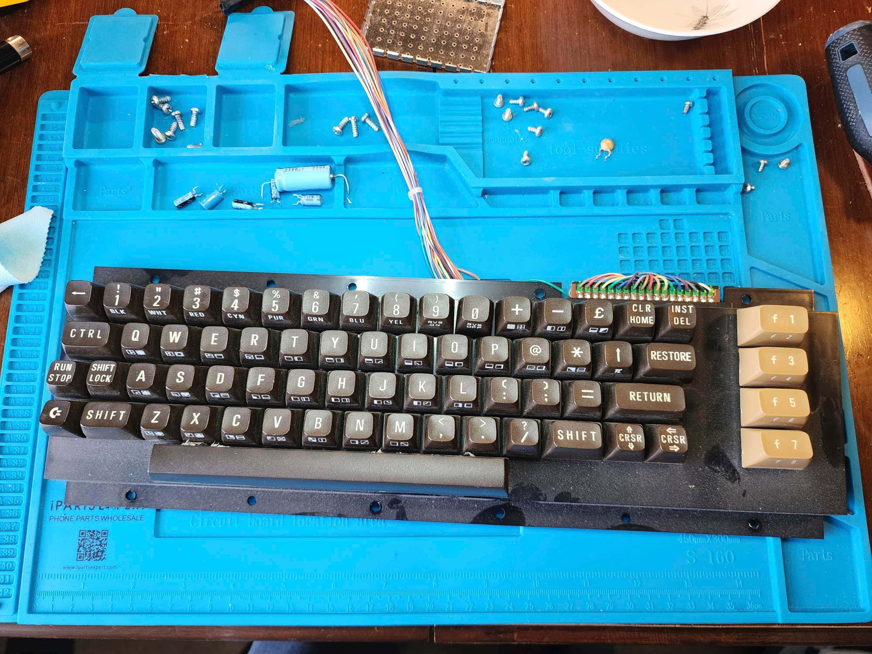
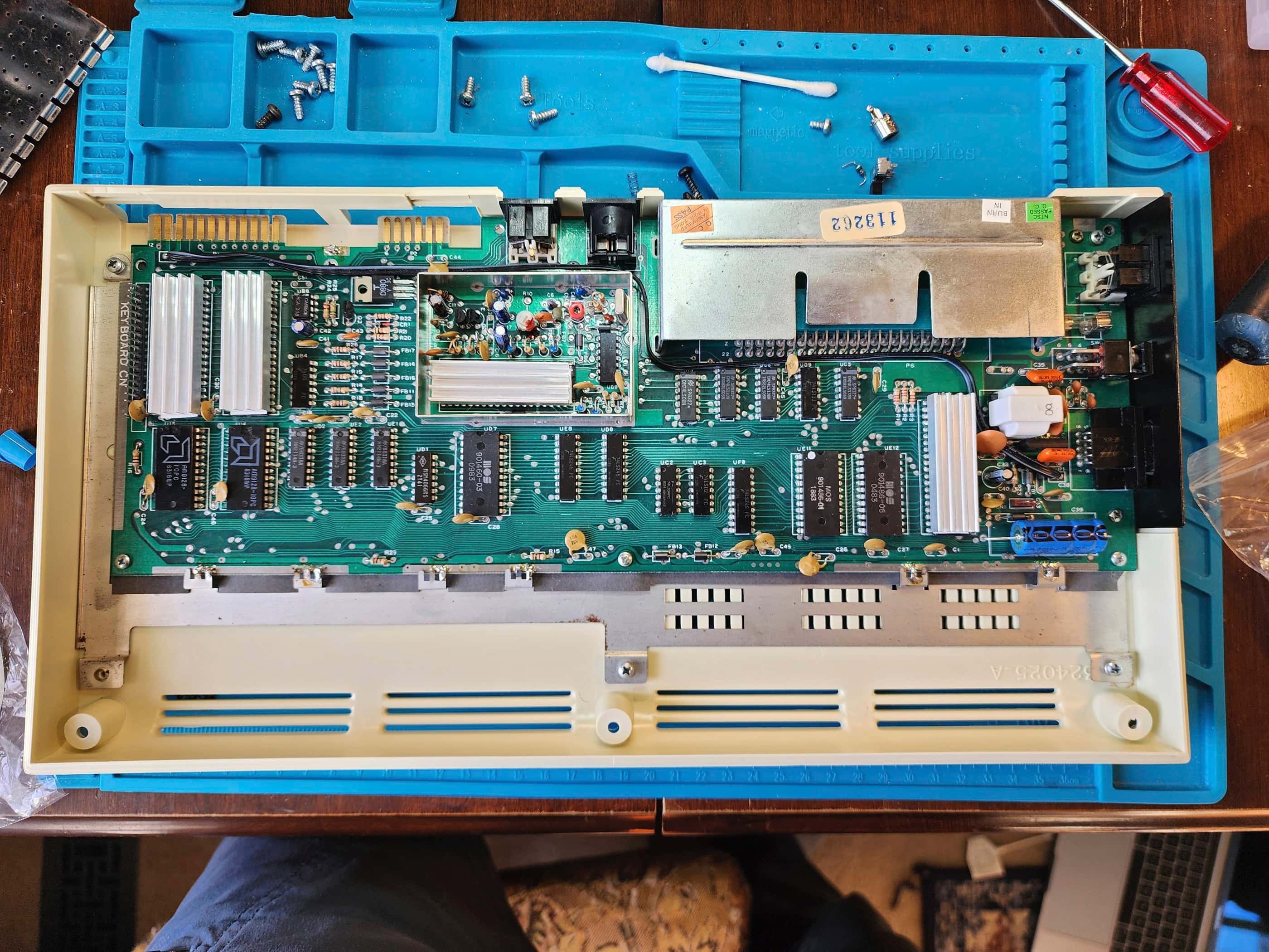
On opening the unit, I was surprised at how dirty it was inside. It had obviously been stored in a dry location, but the board was coated in a thick layer of dust – more than what I’ve normally found in other consoles of the same vintage. No matter, a good scrub with IPA removed the grime and cleaned the cartridge slot. I also spent considerable time cleaning the keyboard.
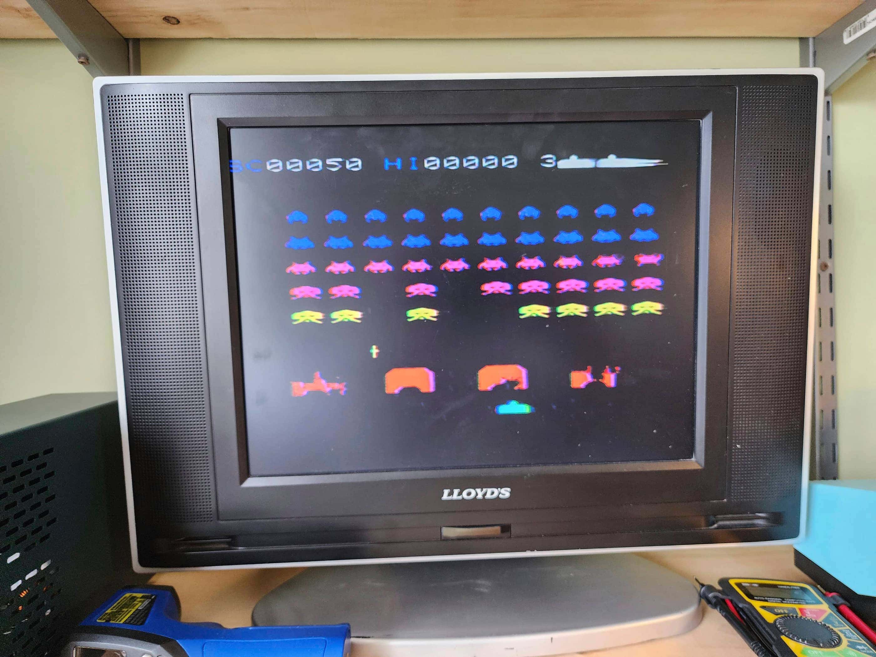
Given the condition, and in case the video issues did not originate with the RF modulator, I recapped the board. A quick test showed that everything worked, but the RF modulator was still sketchy. I even replaced the two caps inside the modulator, which helped stabilize the output, but when I played more graphically involved games like Garden Wars, the output deteriorated quickly until it was unplayable.
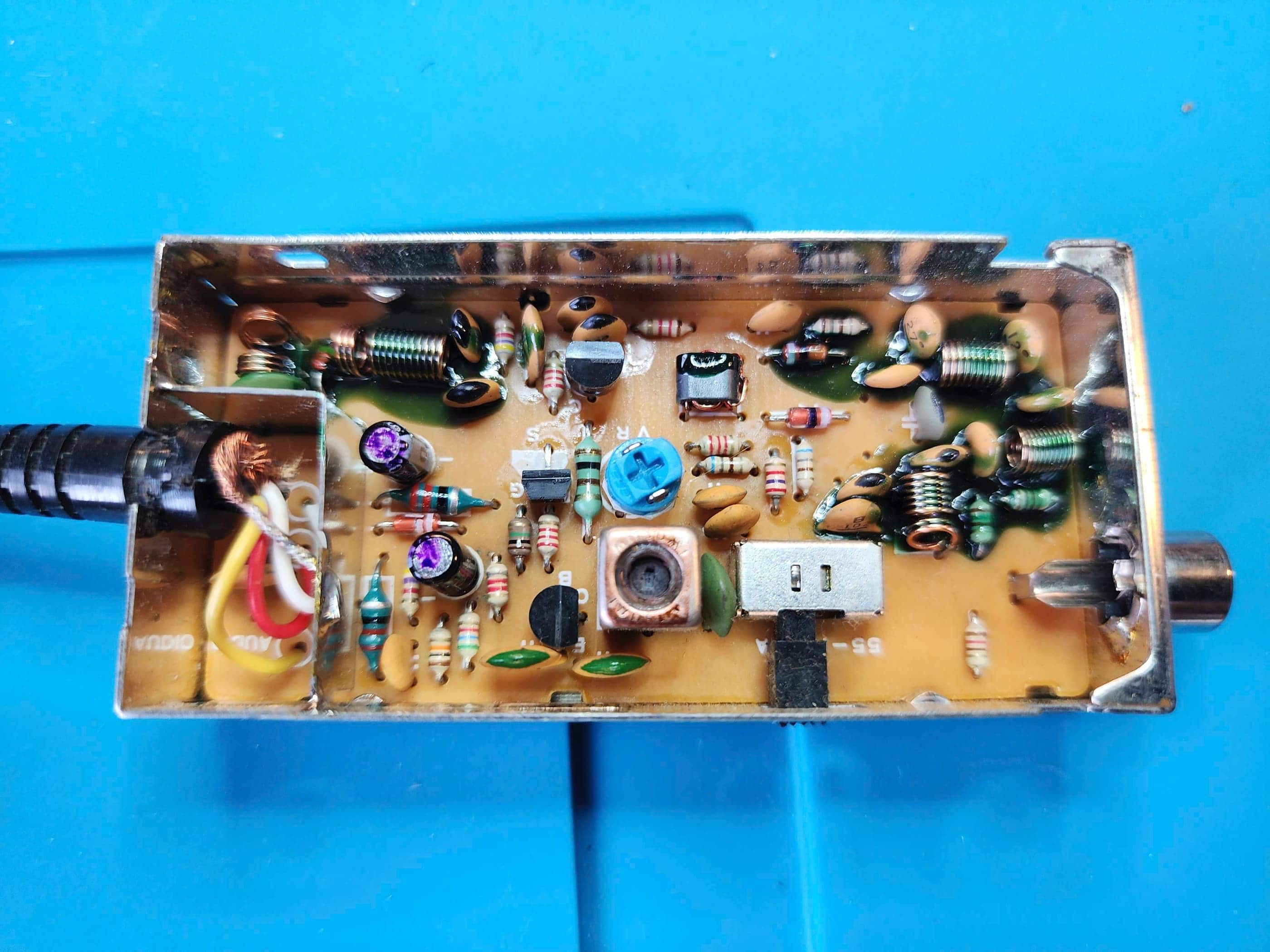
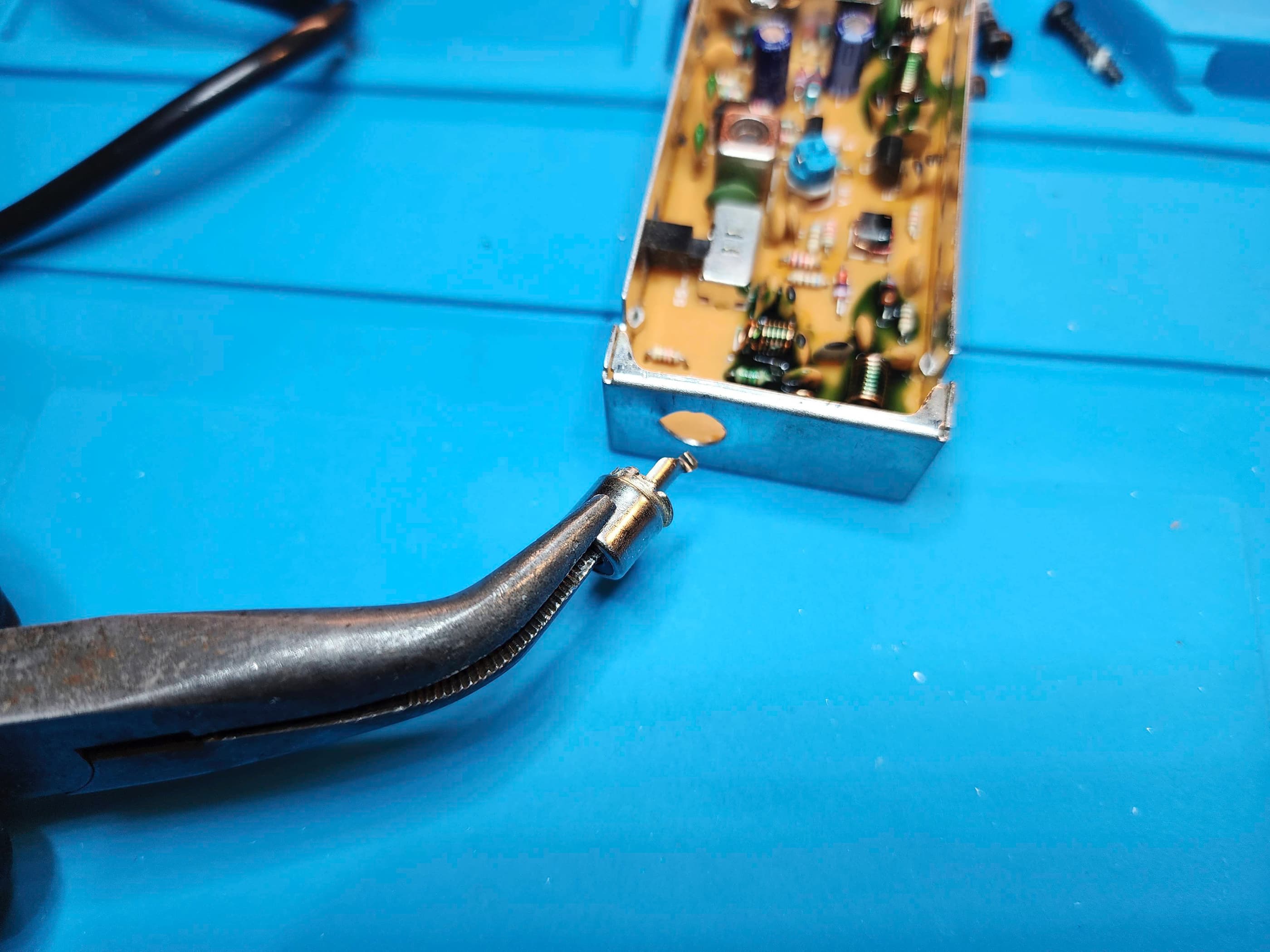
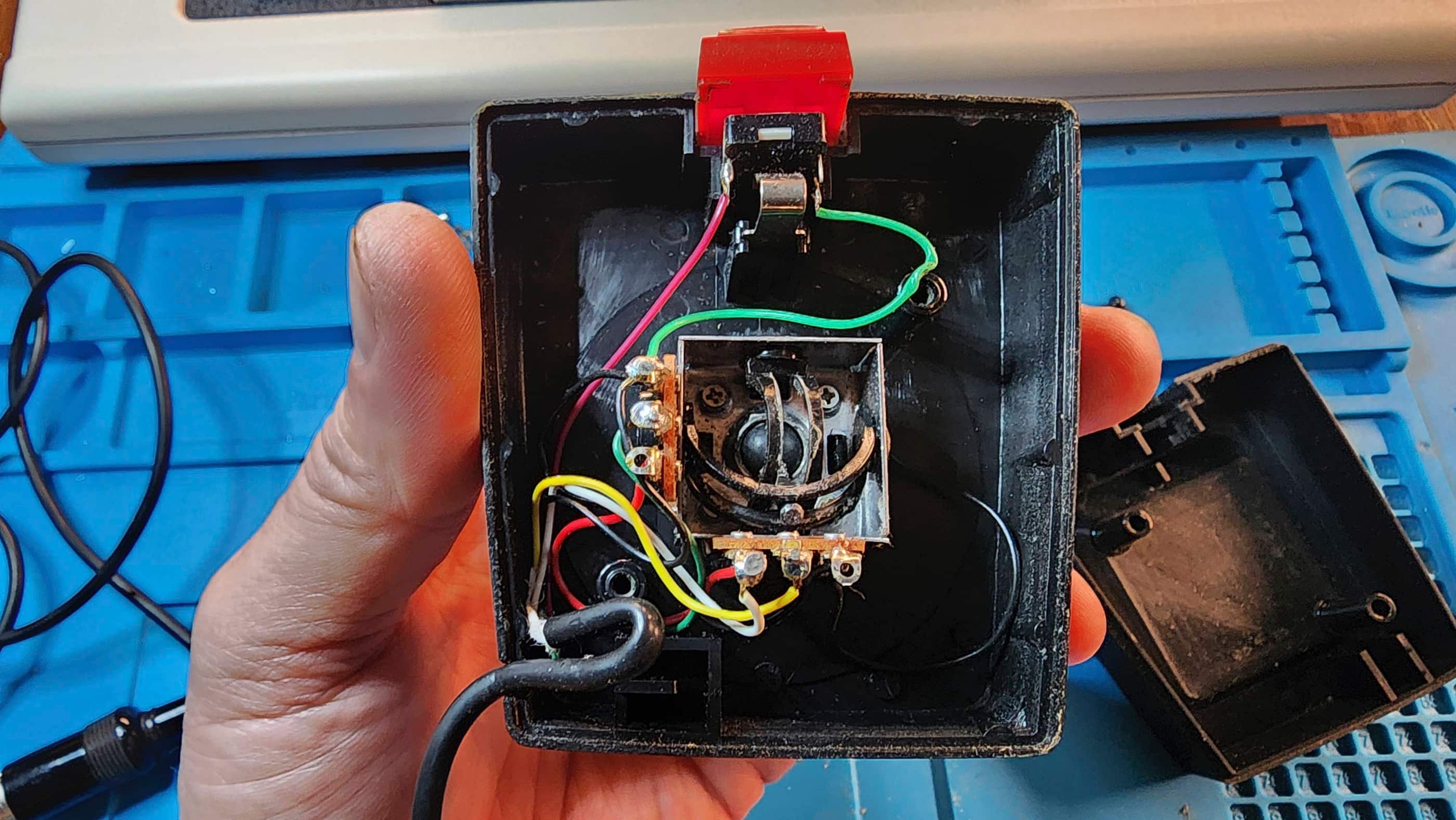
As I did not have a 5 pin DIN to composite replacement cable, looked to modify the existing cable. Knowing that the VIC20 supplied a great composite signal along with audio through the DIN cable to the RF modulator, I debated whether to simply remove the modulator and affix a couple RCA cables as others have done, or – and this was the idea that popped into my head just as I was about to cut off the modulator – preserve the RF modulator by replacing the RF jack with a 3.5 mm TRRS composite jack.
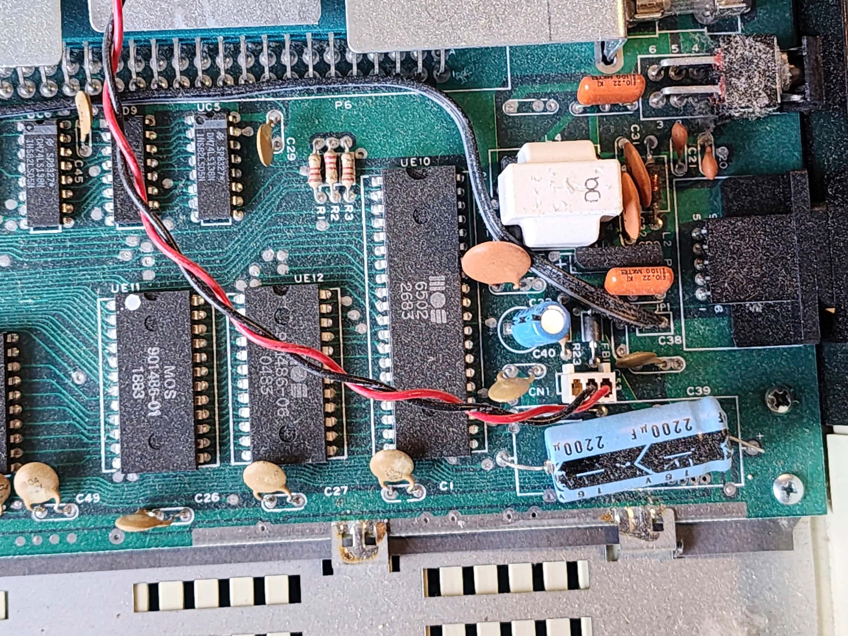
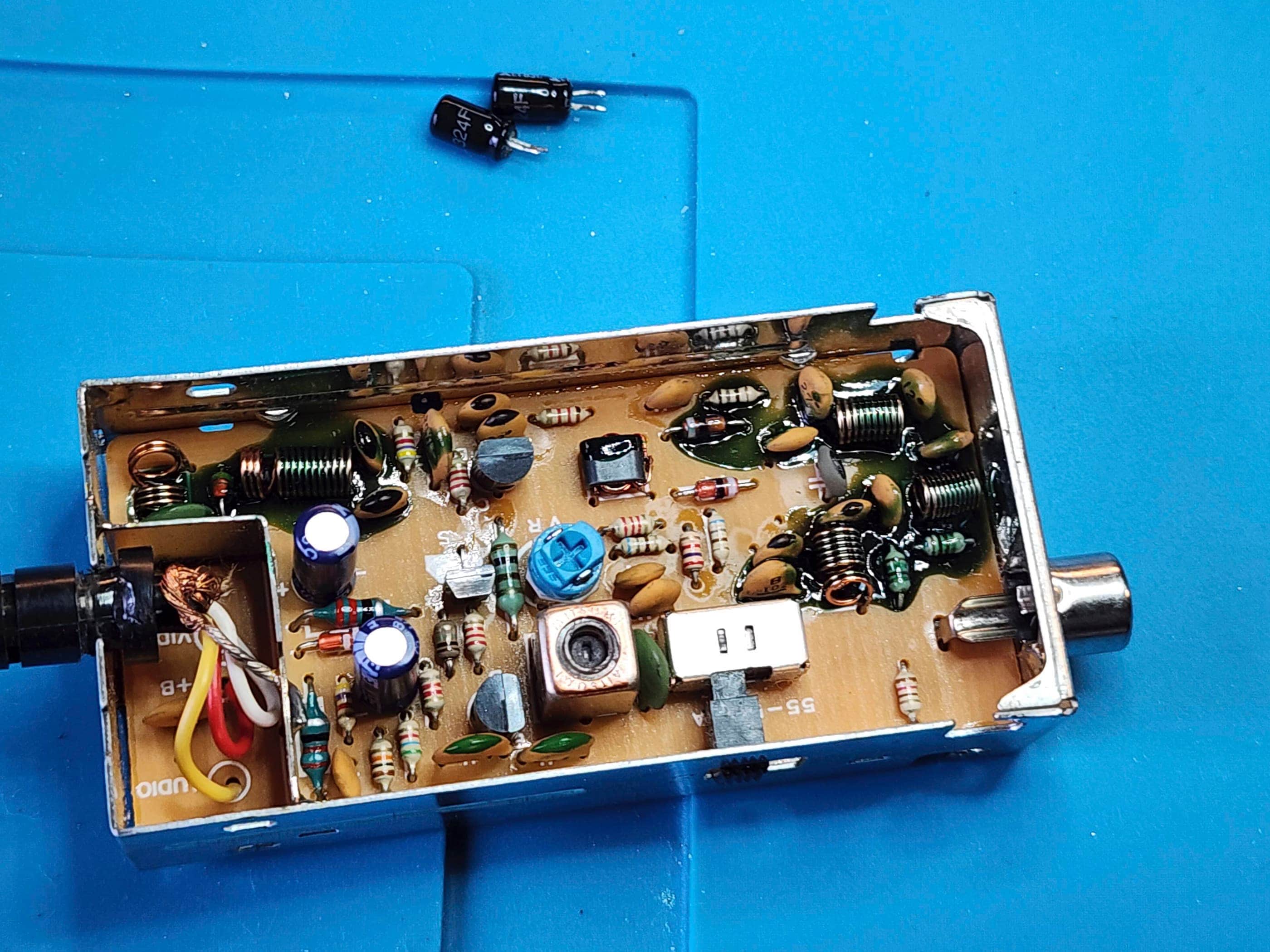
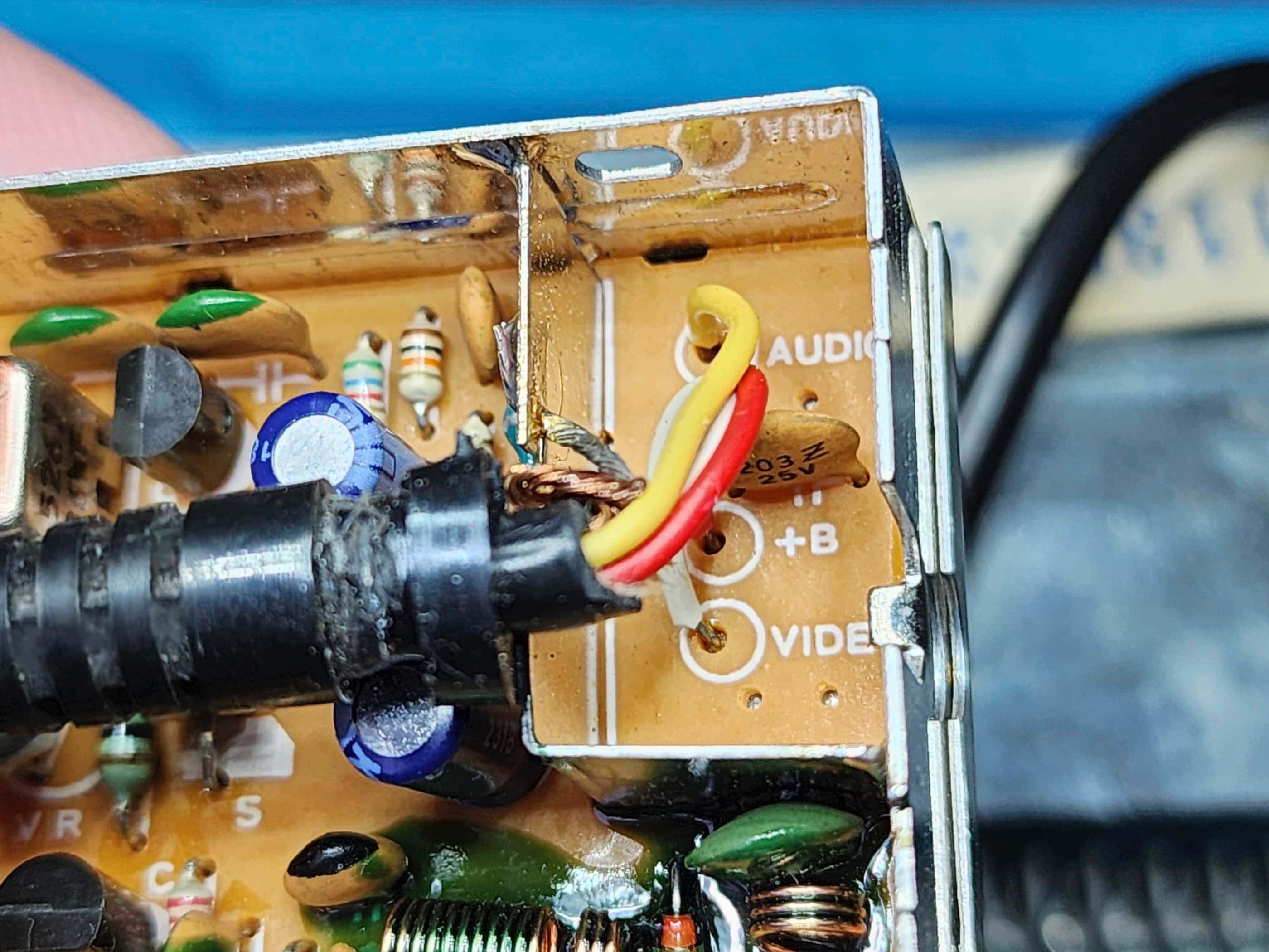
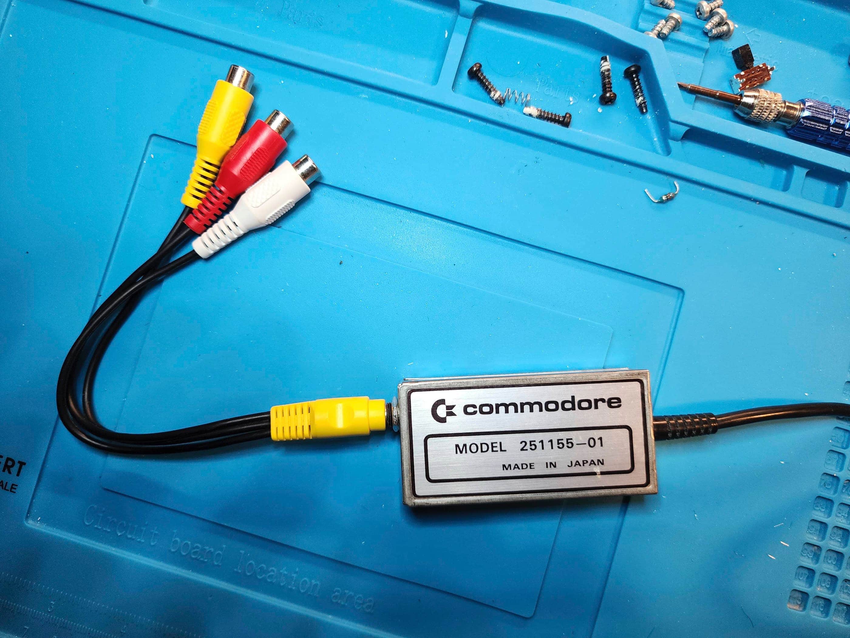
This seemed to me to be a cool way to keep the original aesthetic and authenticity of the system, but upgrade it to a much better output. To do this was simple and merely required removing some components from the RF box. First, I de-soldered and removed the RF jack. I then drilled the hole so it was slightly larger so it would fit the TRRS jack. Next, I removed the channel select switch and anything that would interfere with the placement of the TRRS jack. I then de-soldered and removed the two electrolytic capacitors along with the blue 22 ohm resistor that was connected to the audio wire. As the 6v power supplied to the modulator was not needed, I snipped the red wire from the cable and from the modulator. Next, I attached a wire through the hole where the anode of the electrolytic capacitor met the trace coming from the input video wire, then I attached a wire through the hole where the removed resistor met the trace coming from the input audio wire. I then soldered a ground wire to the box at the point where the incoming ground was also soldered. Finally, I soldered all the wires to the TRRS jack, making a bridge between the two audio points so the sound (mono) would come from both the red and white audio cables. I then installed the TRRS jack, deliberately leaving lots of wire slack inside the box to ensure an easy fitting of the jack, before closing everything up.
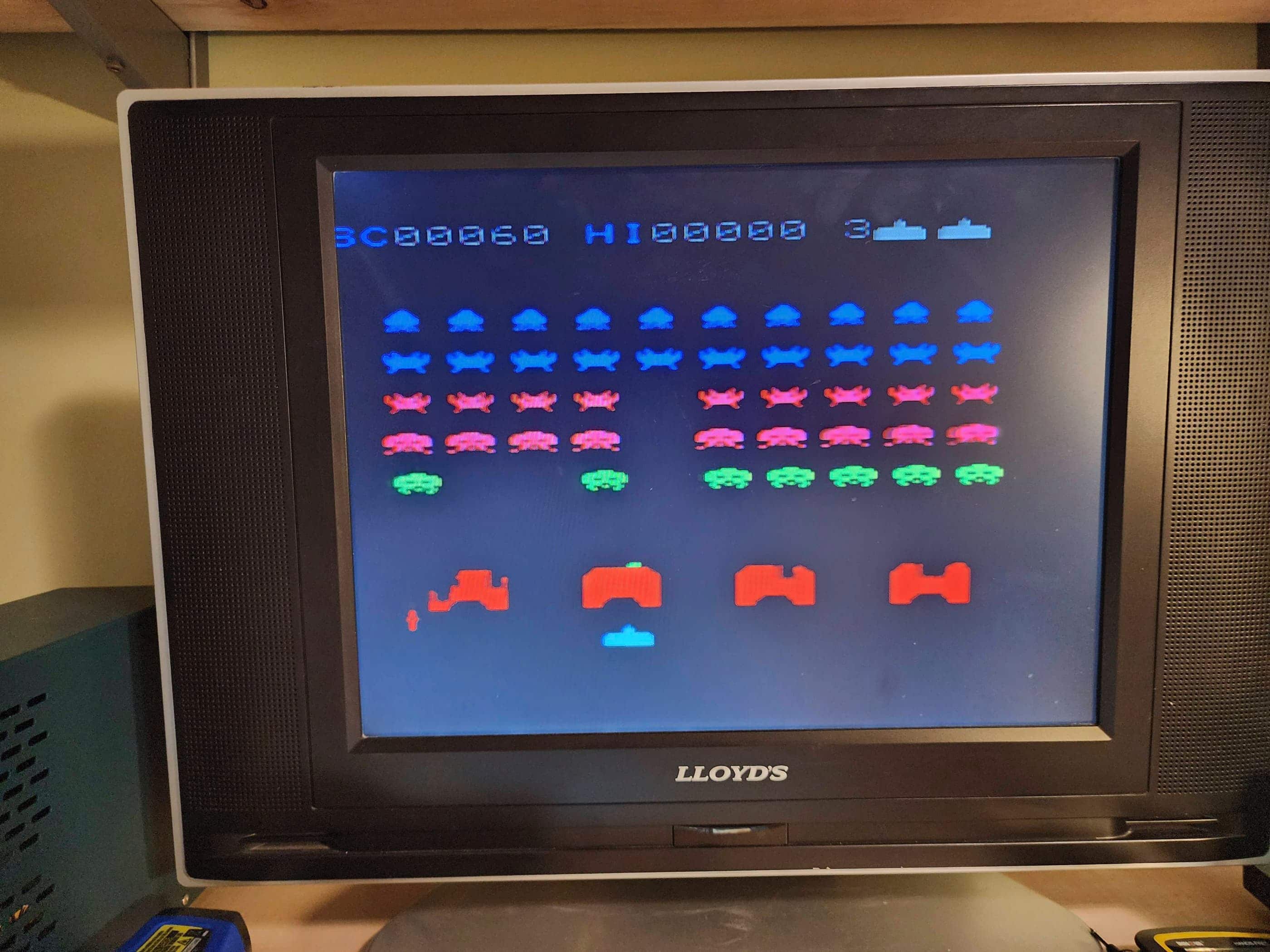
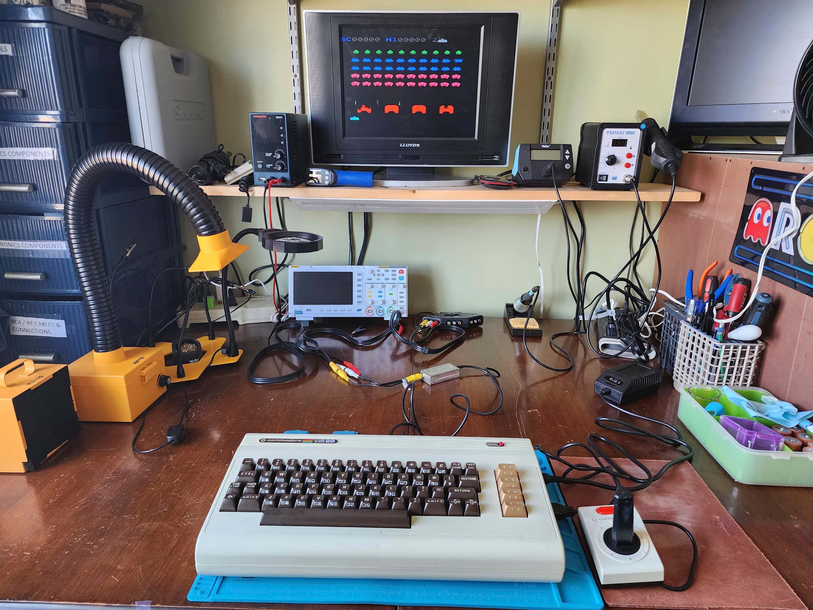
That was it. It was perhaps a bit more convoluted than simply soldering on a new RCA cable, but in my mind, it was far more elegant. The new TRRS jack did not look out of place on the old RF modulator, and as I had paired it with a 6” 3.5mm to female RCA adapter, it would allow for more flexibility going forward. A quick test show a massive improvement in video and audio quality, with no glitching whatsoever when Garden Wars was played. Success!
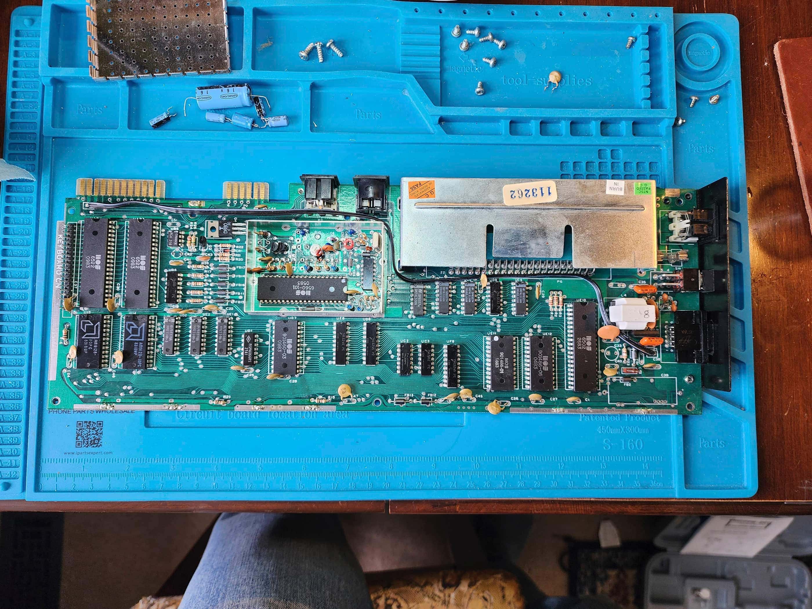
My next step was to reassemble the computer, but before I did, it dawned on me that I still had some DIP40 heat sinks and thermal tape leftover from my work on the Bally Astrocade. That’s when I decided to put these onto the two VIA chips, the all-important custom VIC chip, and the CPU. I also left the cover off of the box surrounding the VIC chip for better airflow.
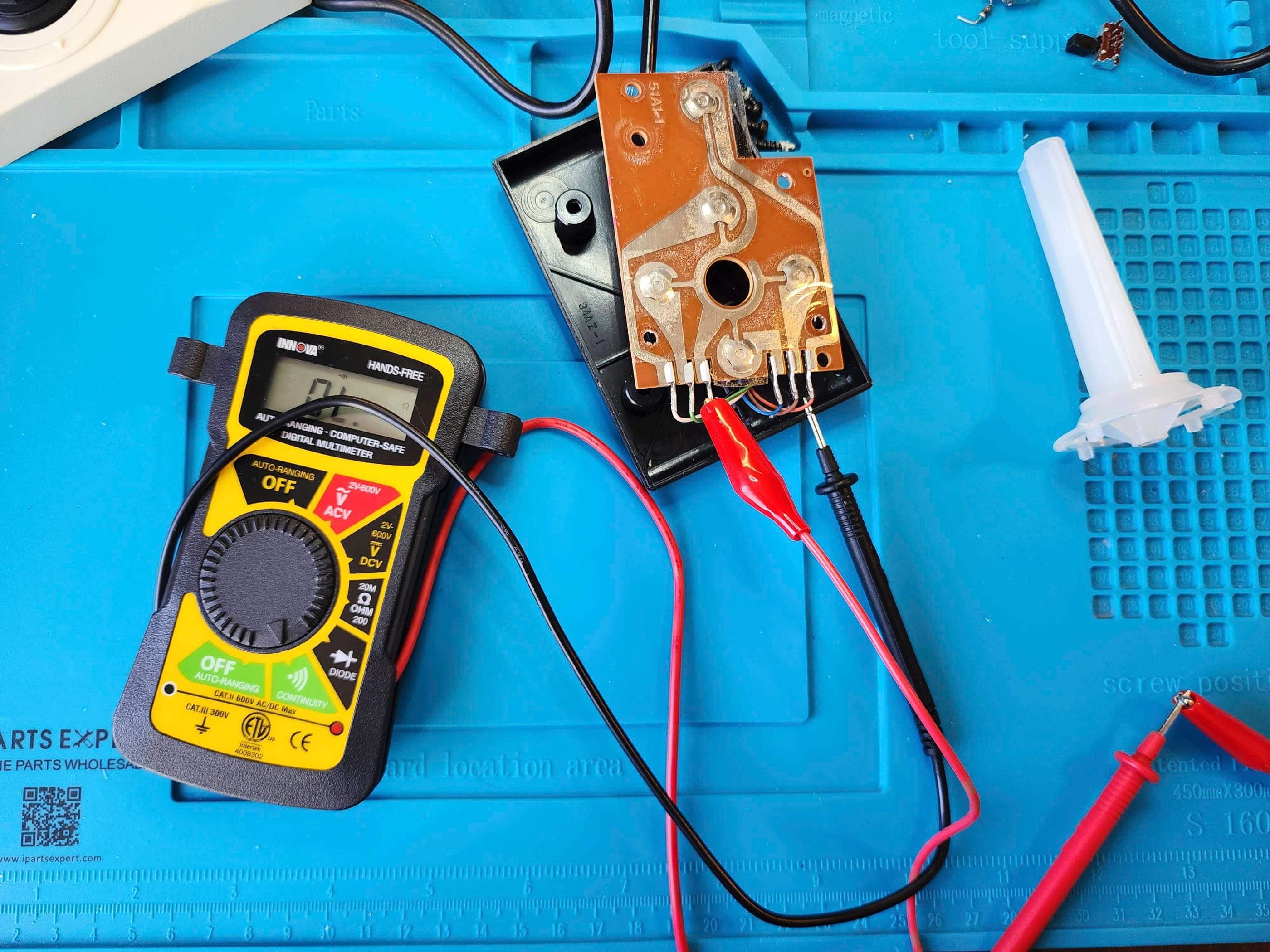
I then thoroughly washed and shined the case before reassembling the computer. Once done, I proceeded to inspect and recap the Datasette along with testing and cleaning the white Commodore joystick that I had found on Ebay. As I don’t have any cassettes to test the Datasette, all I could do was confirm that the belts were intact and that the machine’s buttons seemed to do what they were supposed to when hooked up to the VIC20. I also cleaned the play heads with IPA.
Once the machine was back together, I tested it the joystick and it seemed to also worked well, though it was obvious that Commodore did not put a huge emphasis on the build quality. Anyway, I’m very pleased to have this fantastic piece of history as part of my collection. 🙂
Parts & Products Used: 99% isopropyl alcohol; Chemical Guys Natural Shine; electrolytic capacitors (radial) – 16v 10μF (2); 16v 47μF (1); 16v 100μF (1); 50v 1μF (1); electrolytic capacitors (axial) – 16v 2200μF (1); 22 gauge wire; 3.5mm TRRS jack; 6″ 3.5mm to RCA female adapter; Keelog Vic 20 / C64 power supply
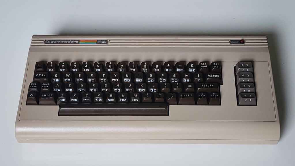
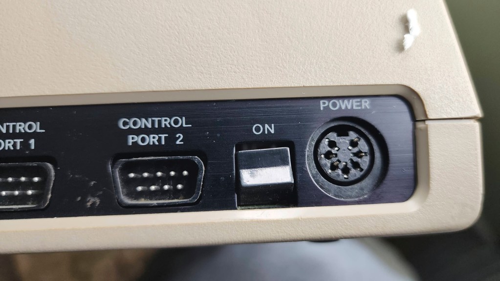
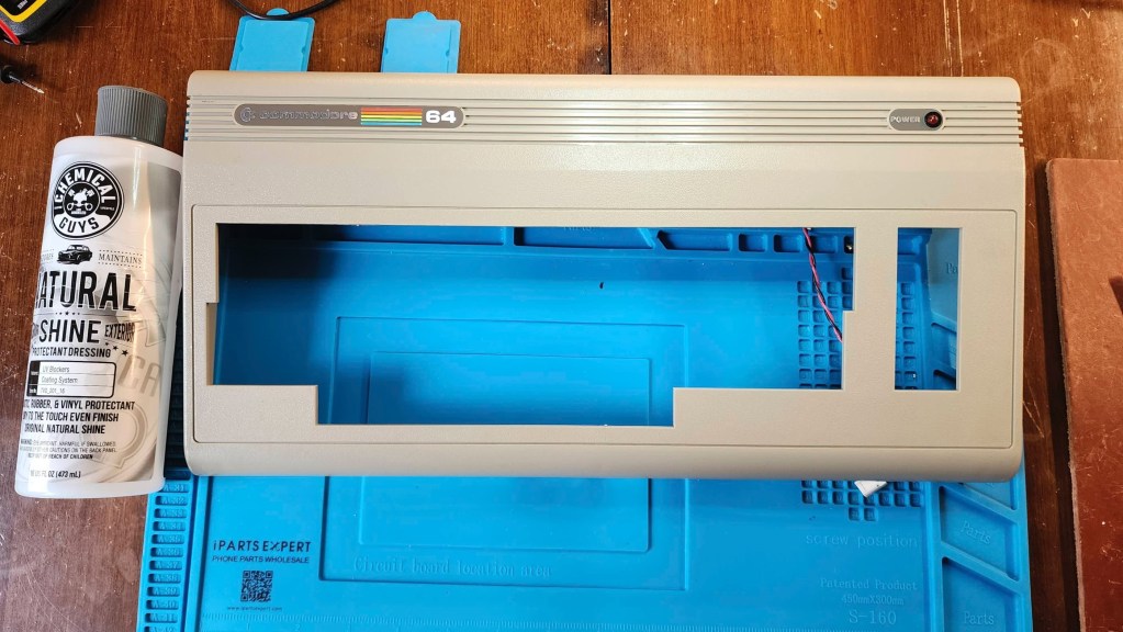
Commodore 64 (ASSY NO. 326298 REV A)
Years (1982-1993)
Interesting Fact: The C64 was my first computer! Before the C64, a Commodore MOS Technology engineering team headed by, Albert Charpentier, and green-lighted by, Charles Winterble, set out to “produce state-of-the-art video and sound chips for the world’s next great video game.” (source) These of course, were the early versions of the VIC II chip and the SID chip. When the President of Commodore, Jack Tramiel, heard about the new chips and the working protoypes in November 1981, he decided that they would go into a new 64 KB computer that would be displayed at the Consumer Electronics Show (CES) in early January 1982. (source) The only problem was, the computer had not yet been designed. That didn’t stop the Commodore team, and with parts and production lines easily switched over from the VIC-20, the C64 made its debut at the 1982 CES, and the rest as they say, is history.
What is interesting about this particular board, and the one I received for Christmas in 1983, is that it was made in Canada. This is because in 1955, Tramiel purchased a Toronto typewriter manufacturer and renamed it, Commodore International Limited. (source) It was from this subsidiary that the Canadian NTSC versions were manufactured. He also recruited Canadian, Irving Gould, to be Commodore Chair in the 1960s. (source)
For a detailed insight into Jack Tremiel and the founding of Commodore, watch the documentary, The Commodore Story by Steven Fletcher.
Condition When Acquired: Fully Functional
Current Condition: Fully Functional


Project Details: This was a special find for me. As I mention on my intro page, the C64 was my first computer and came at the request of my dad who had terminal cancer and wanted to make sure that I didn’t miss out on the computer revolution. He passed away in October 1983, but my mum still made sure that I received a C64 for Christmas that year. It was a great gift but an awful Christmas.
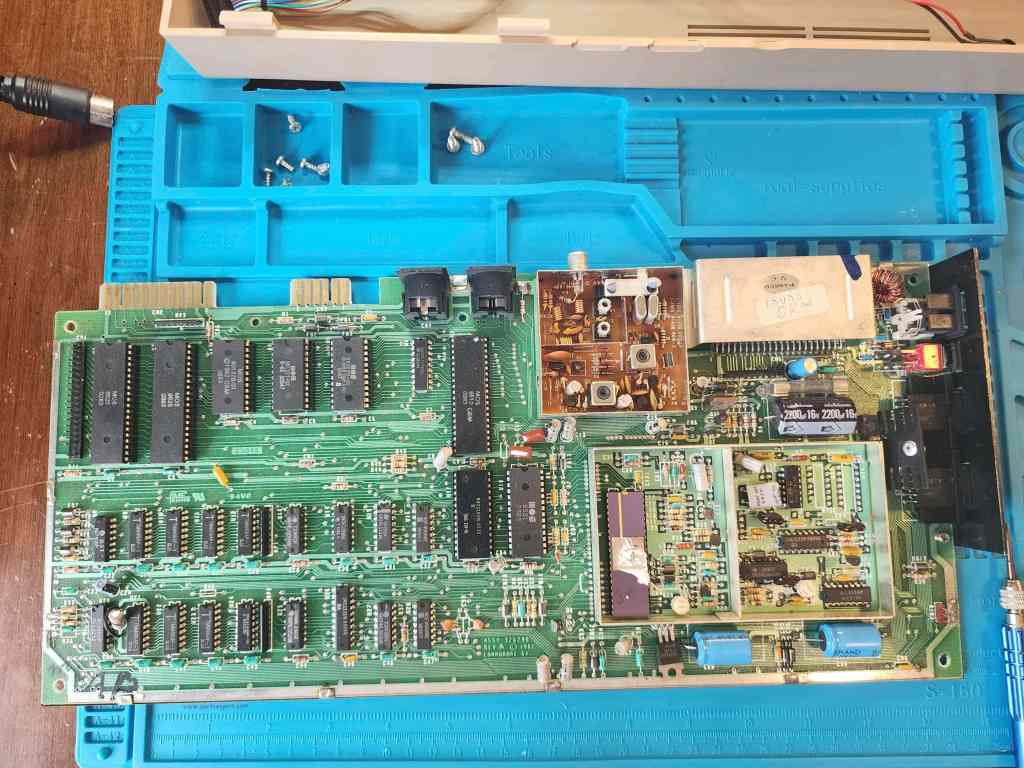
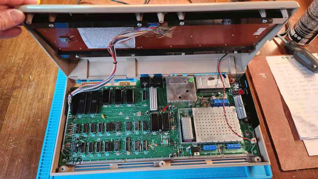
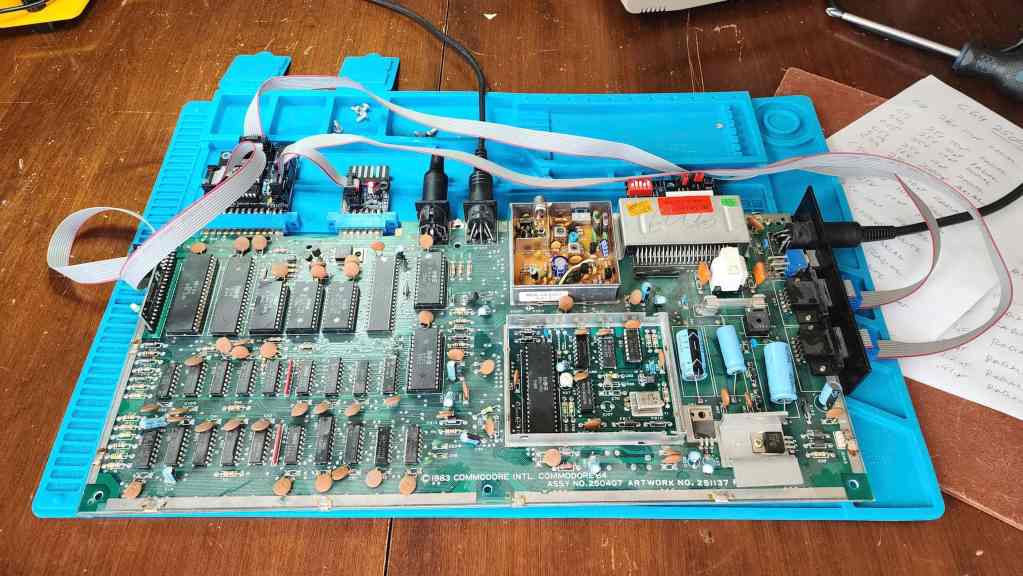
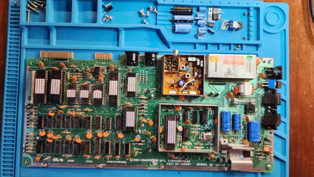
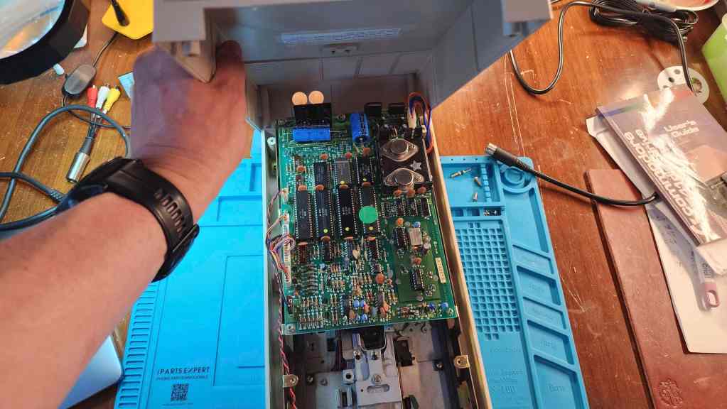
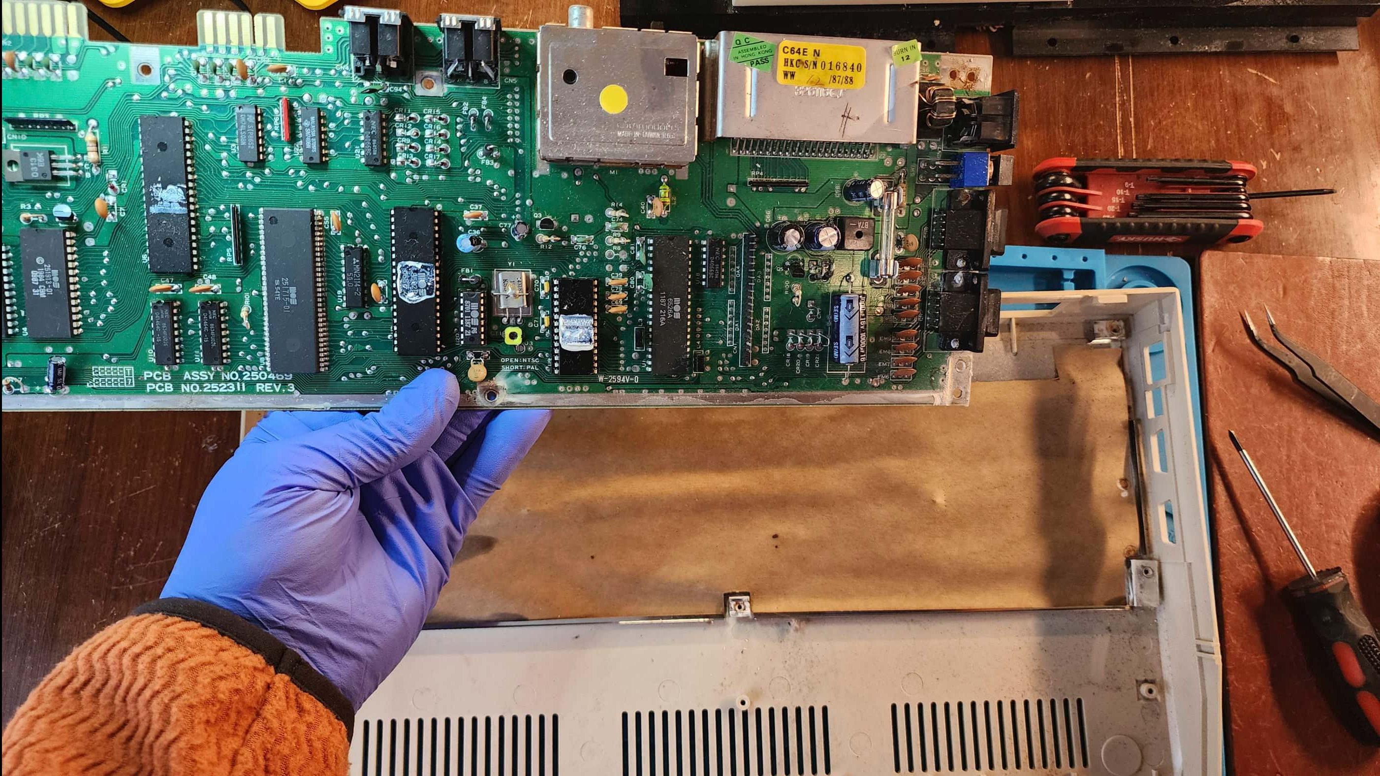
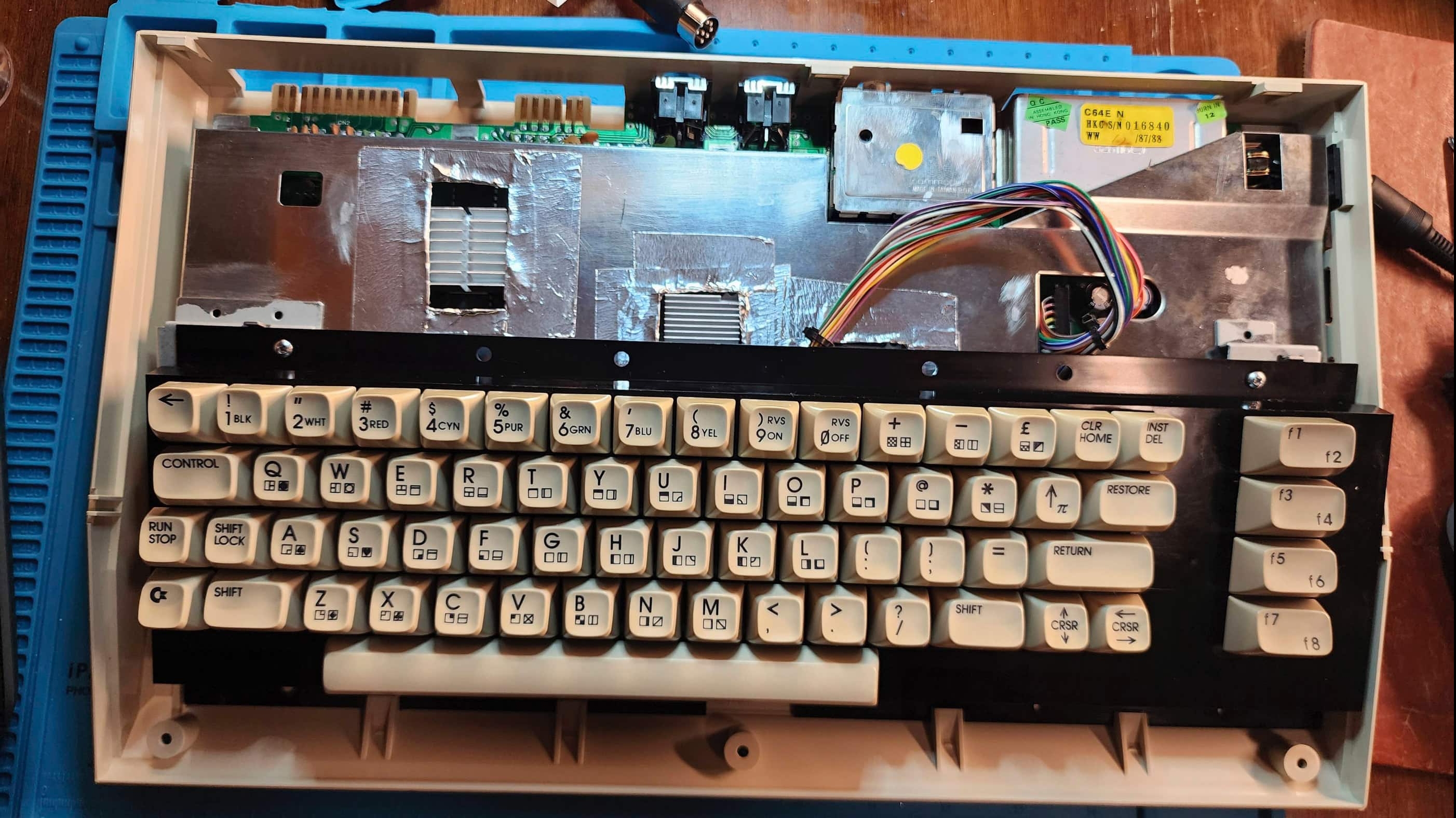
When I saw this popup as an untested unit for cheap, I thought, why not take a chance? Once it arrived, I was surprised at the great condition that it was in. I was even more surprised when I opened it up and looked the board number and the dates on the chips. It was a 1982 ASSY 326298 REV A with only a few chips dating into early 1983. Cool!
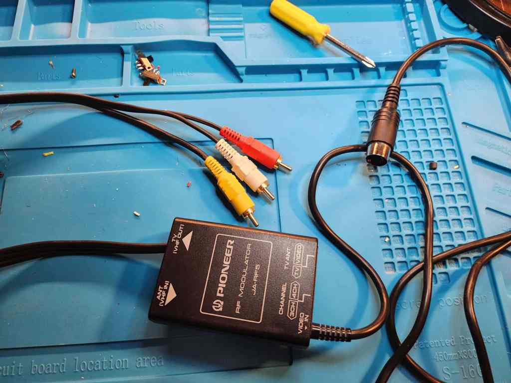
Once it arrived, I realized that it didn’t come with a video cable, so instead of using the one I modded for the VIC-20, I went to my local thrift store where I found a 5 pin RF modulator that I gutted and converted into a new 5 pin DIN cable using some perf board and an old composite cable. When I powered it on using the Keelog PSU that I had purchased for my VIC-20 project, I was further surprised to see that everything worked.
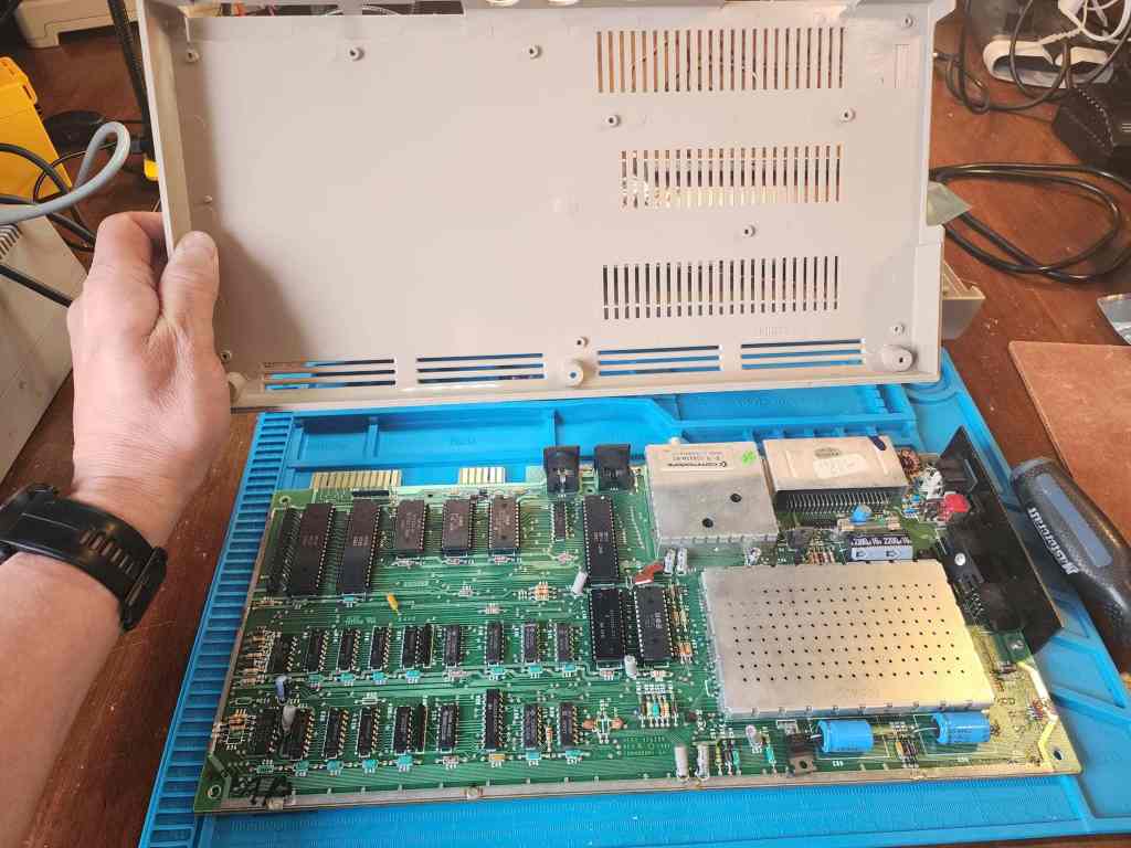
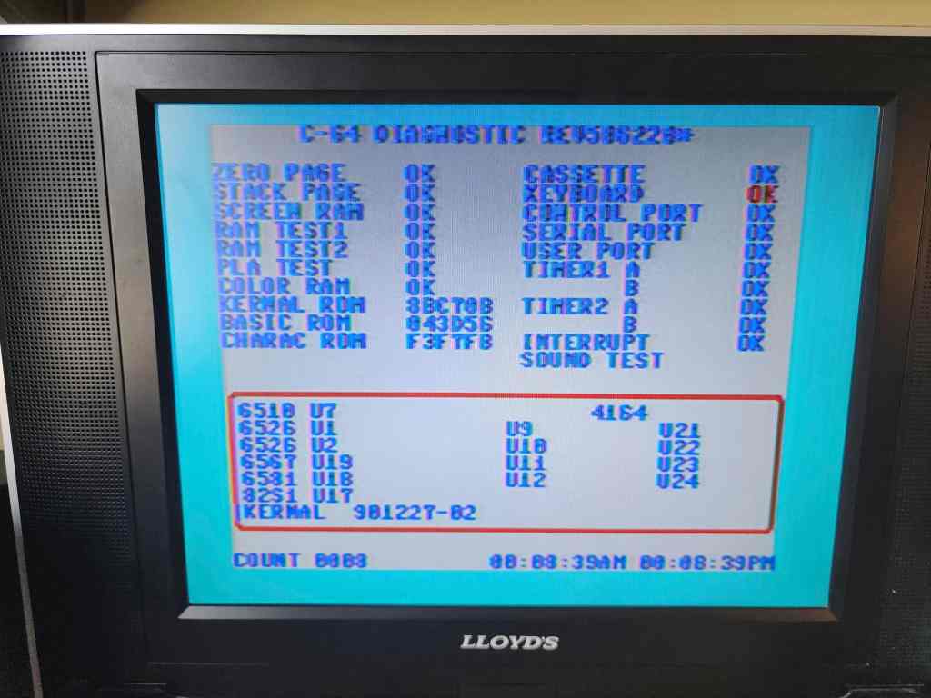
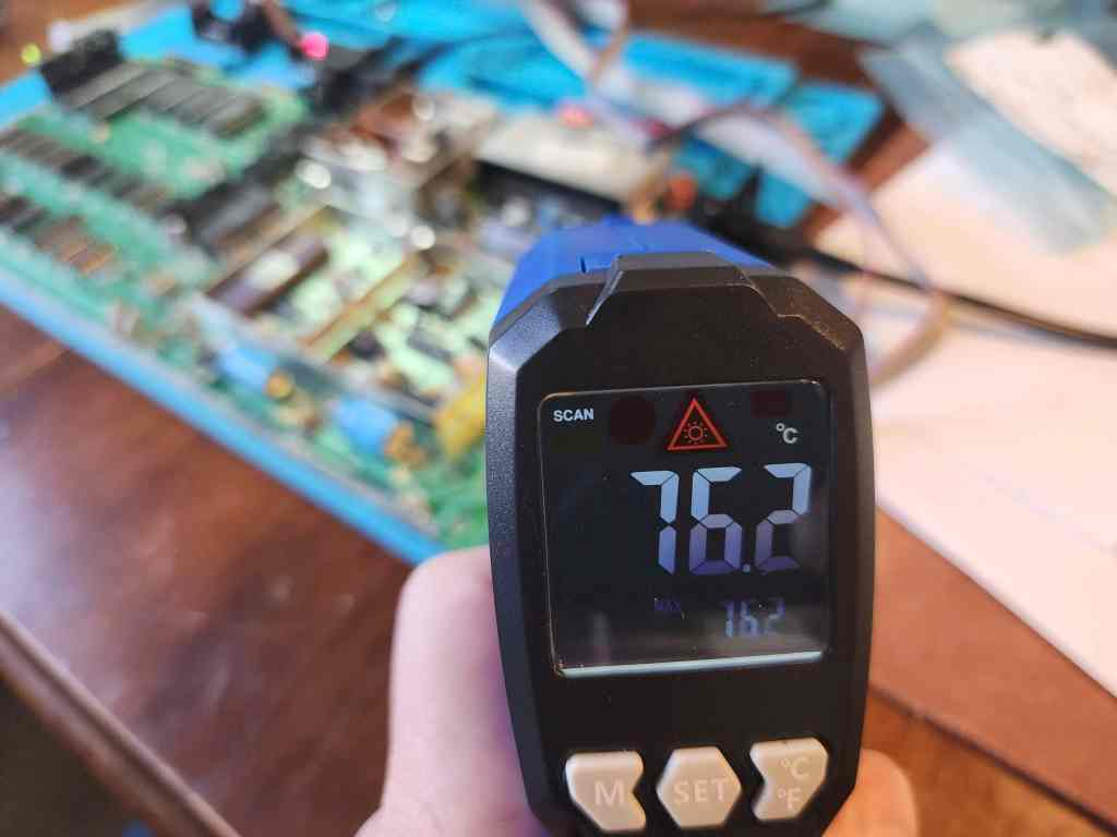
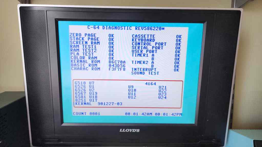
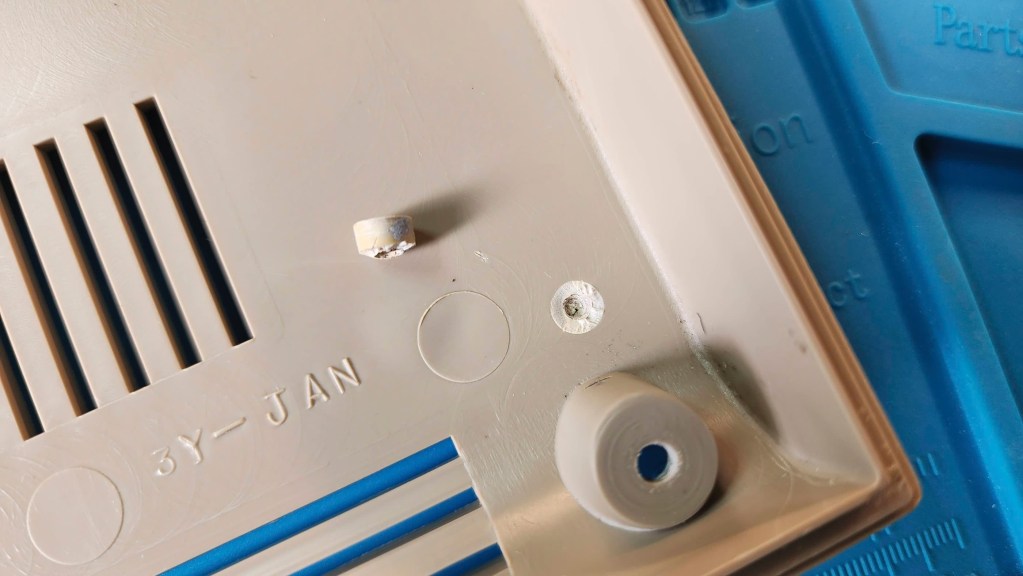
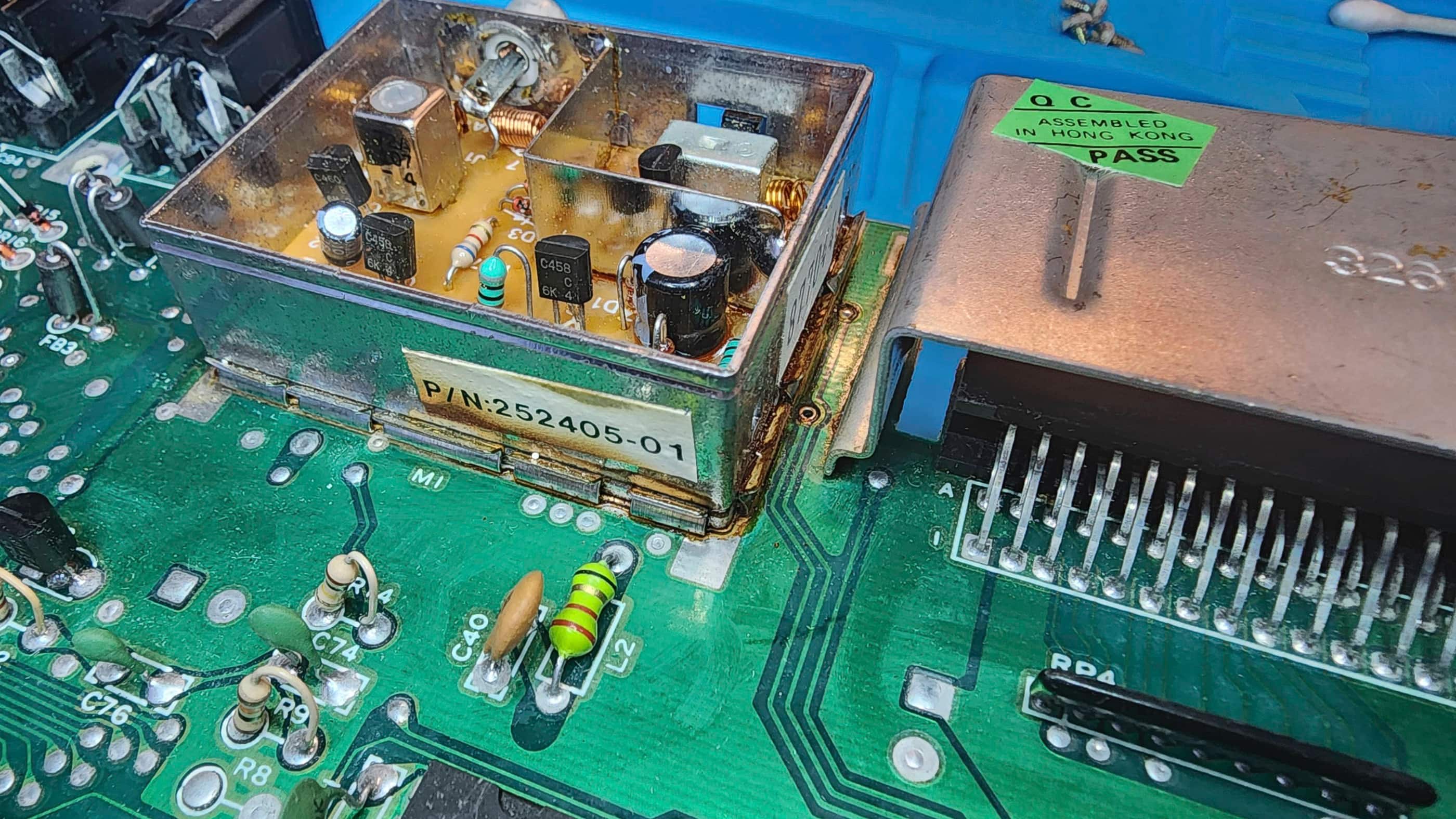
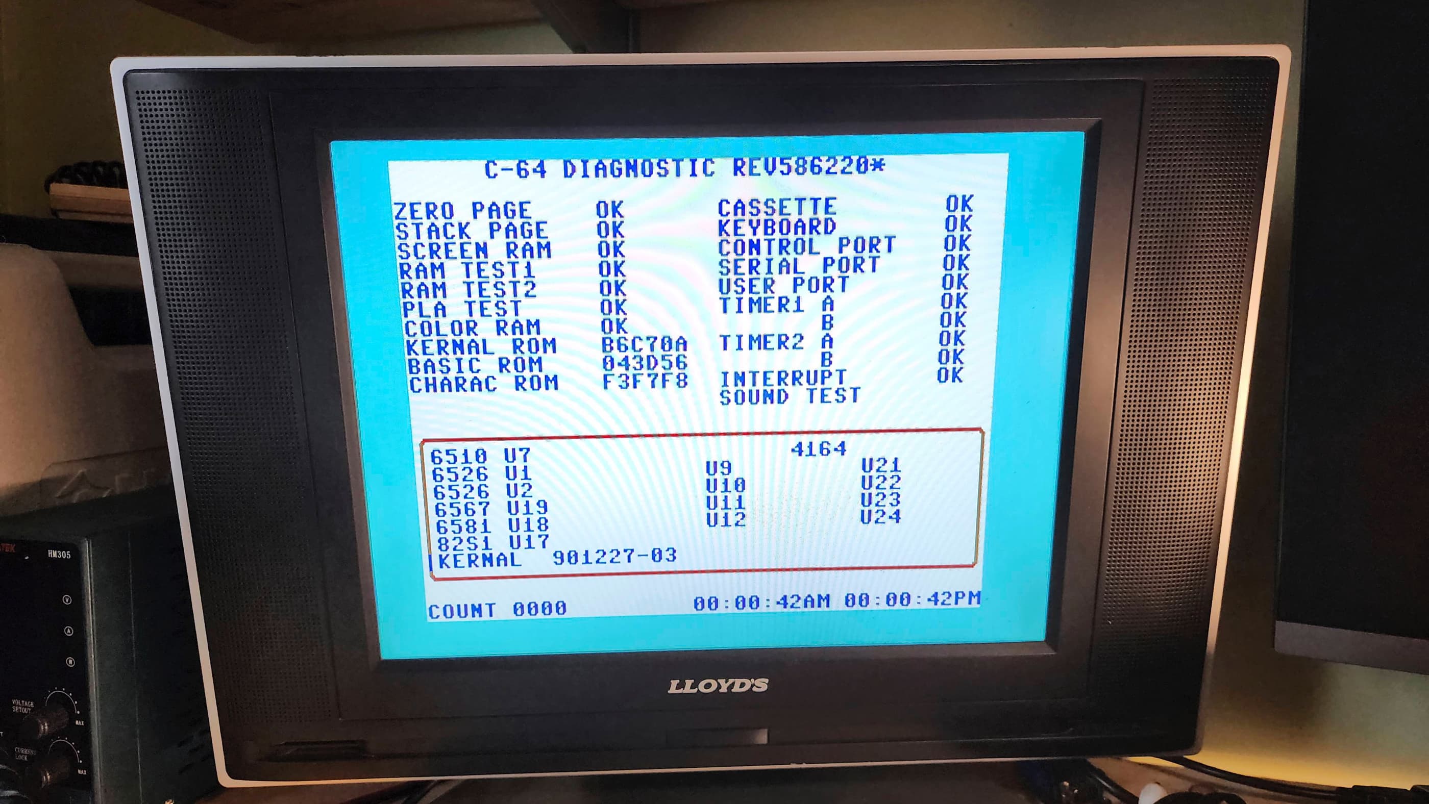
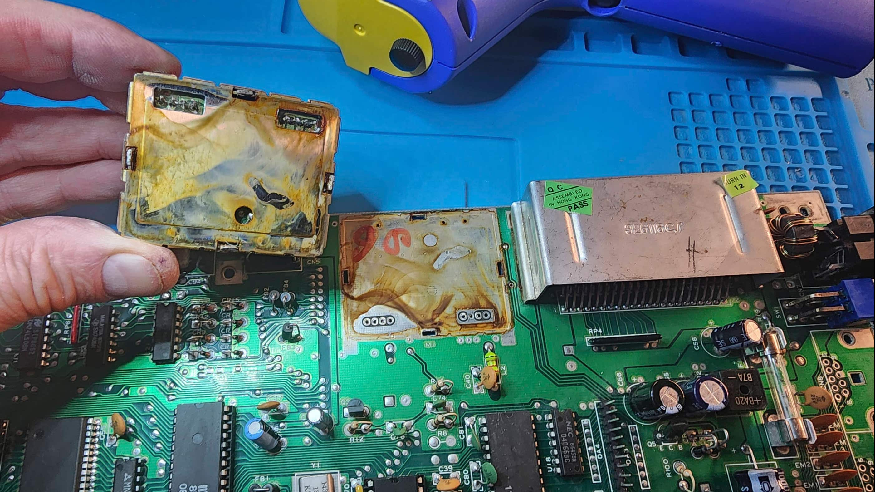
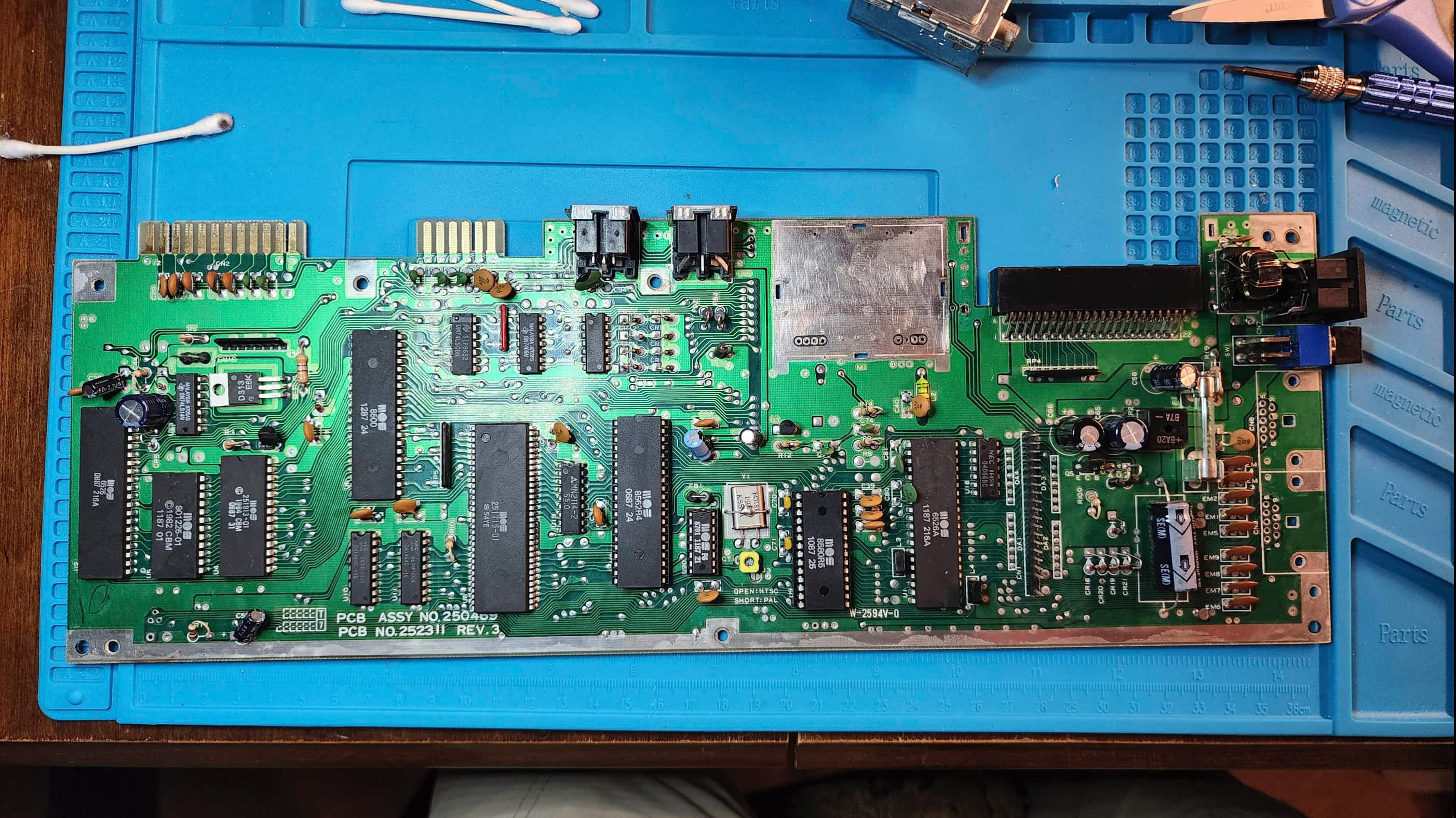
Initially, I was going to just clean it and leave it, then I began testing the components in more detail while concurrently learning from the folks at Lemon64 and Adrian Black. One of the things I learned was that though the REV A boards are usually reliable, the design made them prone to overheating issues, particularly the 7805 voltage regulator. On my computer, the 7805 was riveted to a flat TO-220 heatsink with no thermal paster inbeetween. When I began to test the operating temperature of the regulator, I was astonished to see that it reached over 85 C just from running the C64 Test Cartridge.
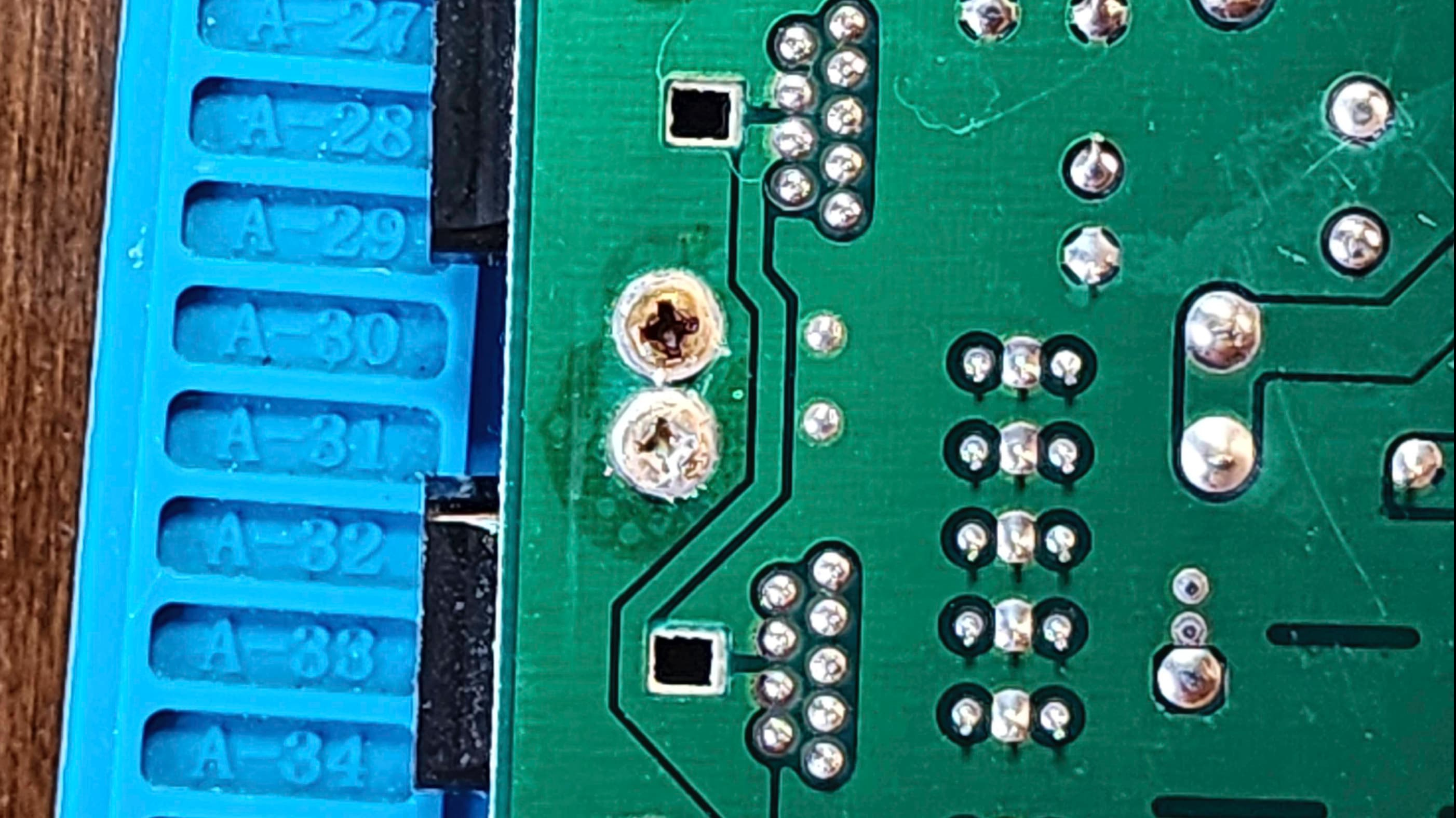
I also noted that capacitor C94 was installed backwards (probably at the factory since it did not look like anyone had touched the board before) and that R10 had a 300 Ω resistor instead of the 120 Ω in the schematic. The only reason I looked for the resistor value was because of what I’d read on Lemon64, where it was determined that the video output quality could be enhanced by fixing this factory error and reverting the value back to the schematic. Since the RV A boards have poorer display outputs than later revisions, I thought this would be a good thing to do.
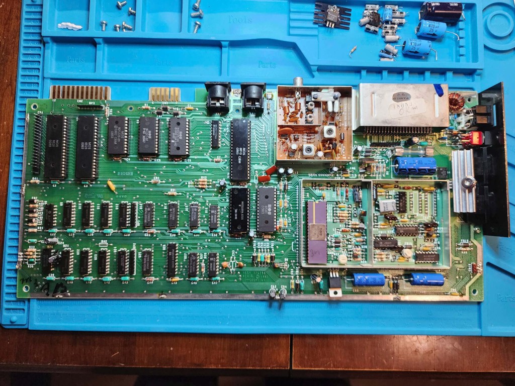
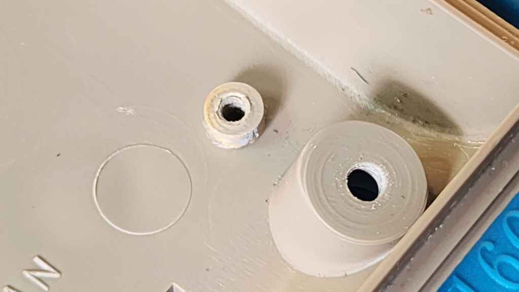
For me, the voltage regulators were my first area of concern and when coupled with fixing the backwards capacitor, I thought I’d be safe and just swap in all new caps and regulators. Once this was done, I set about trying to figure out how to create a better heatsink for the 7805. Later board revisions moved the location and put in a beefier heatsink, but given the limited space in the REV A board, my options were few and far between. What I ended up doing, was drilling a hole in a DIP40 heatsink and then mounting it horizontally to the 7805. This provided a more robust way to distribute the heat but also allowed it to fit within a small space. Testing it after installation saw it get hot, but nowhere near as hot as it was getting before. I’m talking a good 30 C difference running the same test for the same time which tells me that the new heatsink helped but most likely, the original 7805 was probably on its way out. Therefore, just to be safe, I also replaced the 7812 regulator.
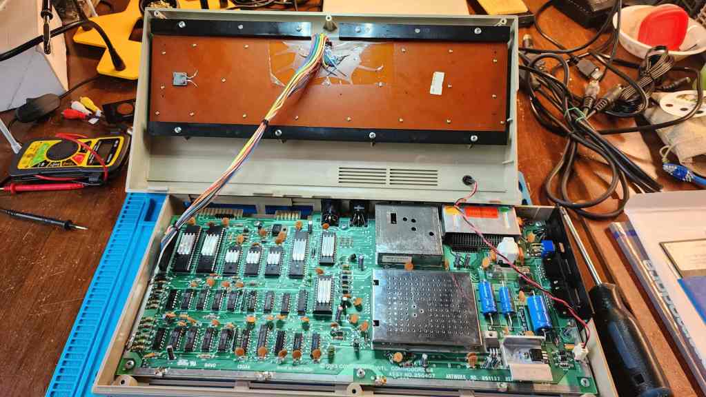
I then changed R10 to a new 120 Ω resistor and can confirm, it does make a noticeable improvement. To fix the computer reset, I added a 1K resistor to R36 and snipped pin 9 of the MC3456 timing chip – but importantly, left the factory installed bodge wire attached to the lower portion of the chip’s arm. Finally, my biggest dilemma, was how to put a better heatsink onto the VIC-II chip to preserve it while still trying to keep some of the board’s authenticity. At the end of the day, I did the Canadian thing and found a compromise.
I found an old NVIDIA Gforce 64 video card I had laying around, and pulled off the heatsink. I then cut it in half so it would fit inside the RF box. I then cut the RF cover to provide an opening for the heatsink fins. Thus, I destroyed a piece of history to hopefully save a more important piece of history. I figured finding a REV A, RF box lid in the future would be easier than a working R56A VIC II, should I ever want to revert it back. Then again, I could’ve just left the lid off…
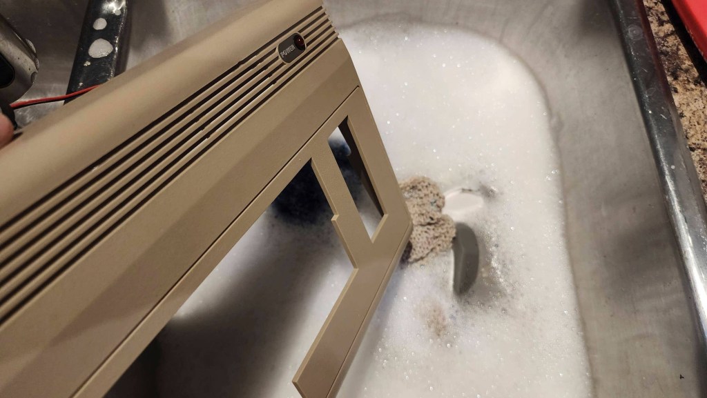
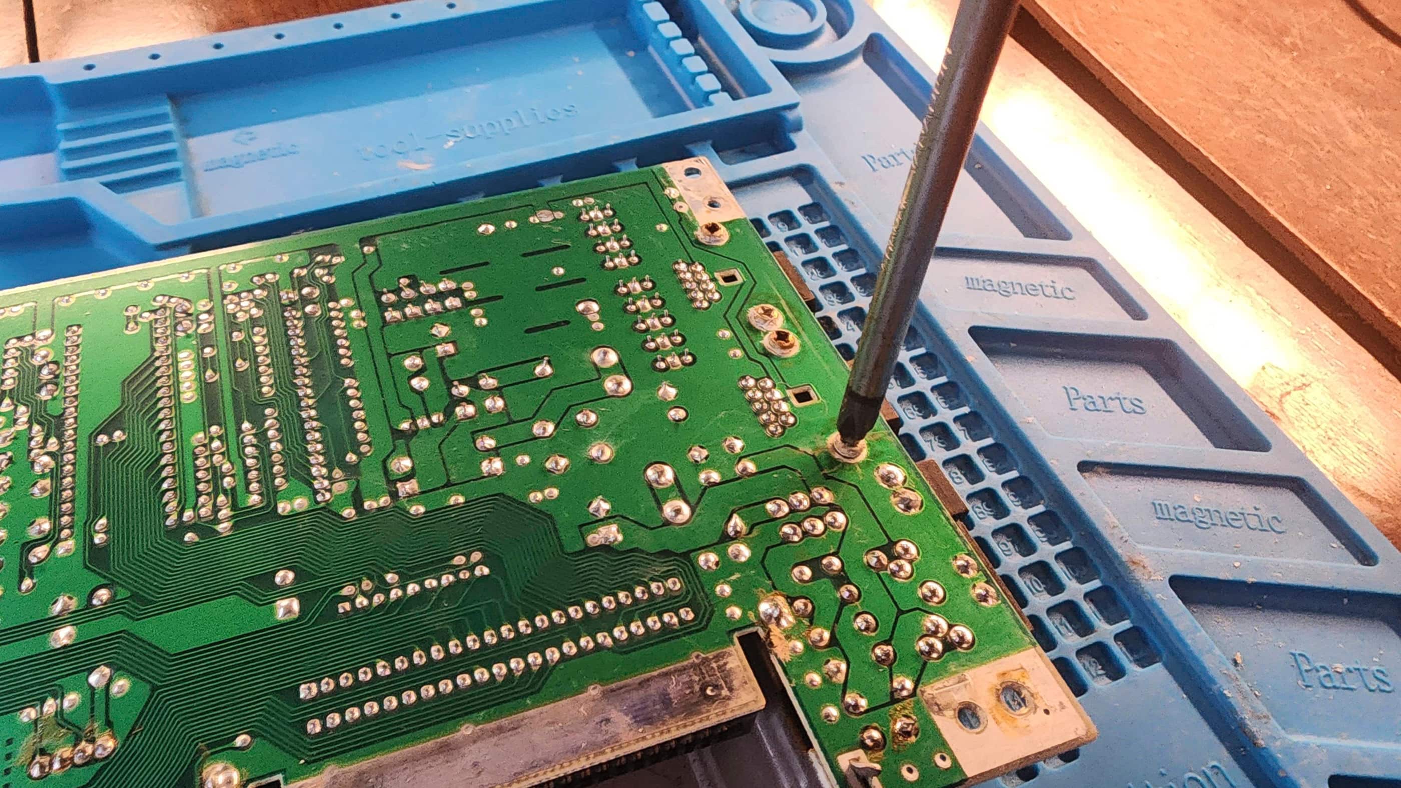
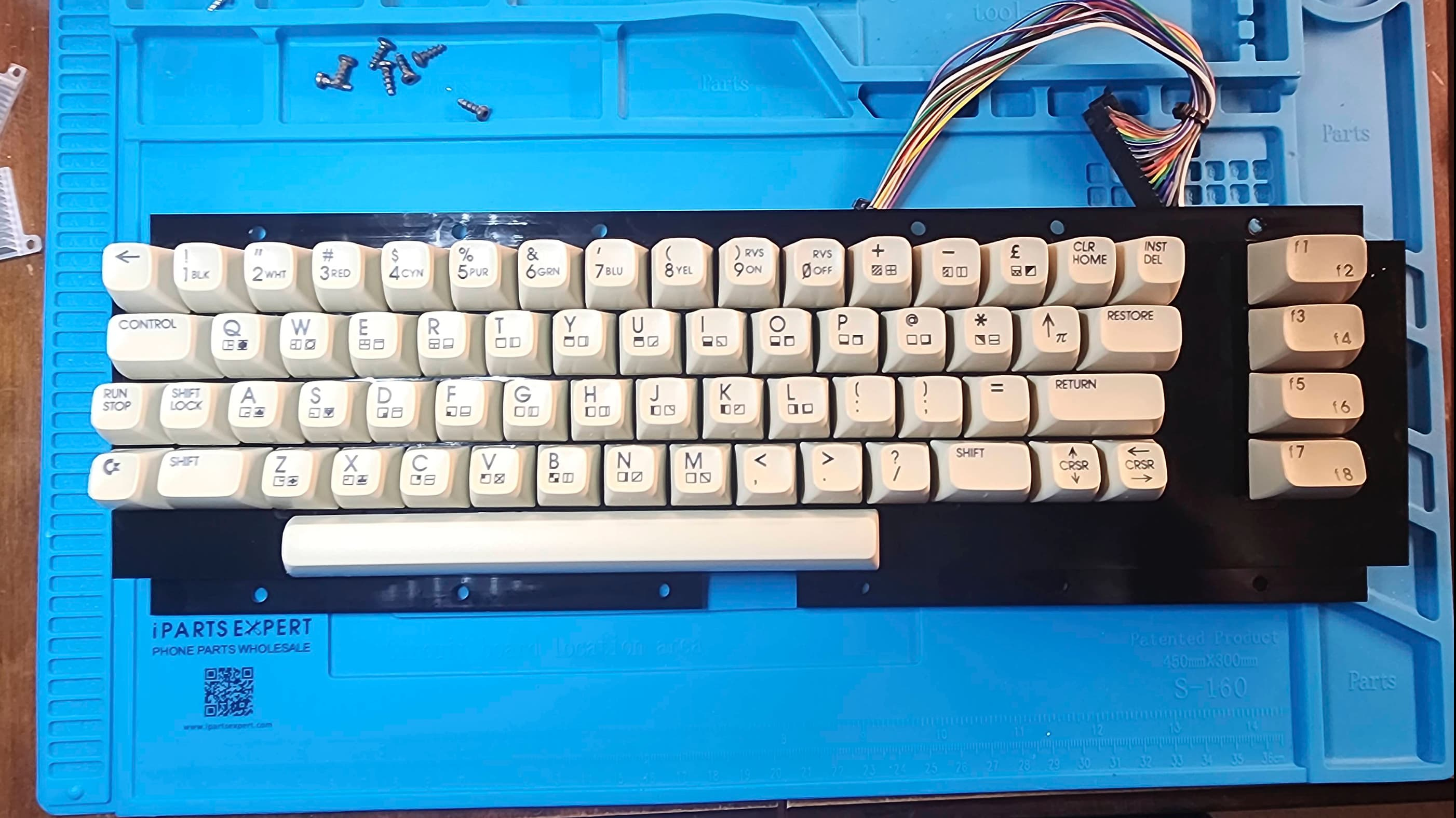
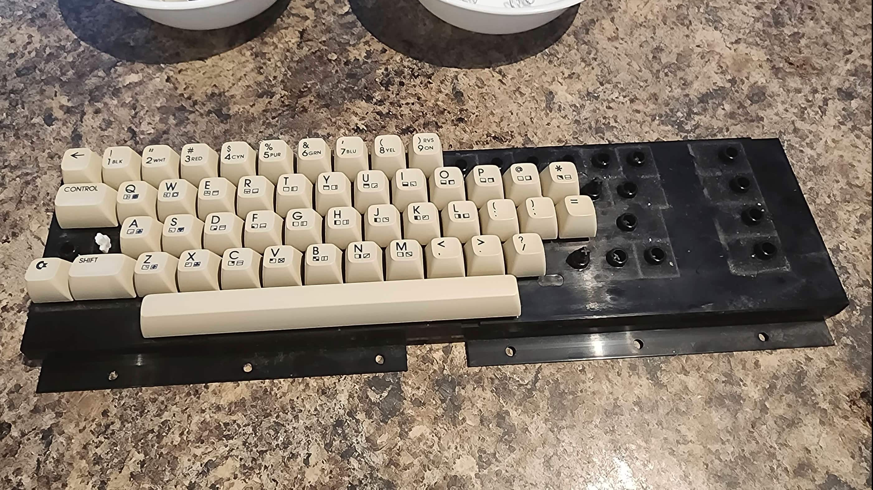
Finally, I reseated and put heatsinks on the PLA, SID, 6502, and the ROMs using thermal tape. I then cleaned the keyboard and the casing. Thorough testing not only showed everything worked as it should, but it things were still running much cooler and to me, that’s what counts.
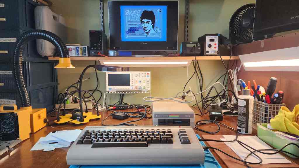
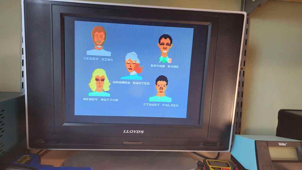
Of course, the first game that I played was, Bruce Lee. My best friend, Jason, and I would play this for hours and as he passed away in 2015, I felt that it was a fitting first game.
Parts & Products Used: 99% isopropyl alcohol; Chemical Guys Natural Shine; Deoxit D5; electrolytic capacitors (radial) – 25v 10μF (13); 25v 100μF; electrolytic capacitors (axial) – 16v 2200μF (1); 25v 470μF; 7805 voltage regulator; 7812 voltage regulator; resistors: 120 Ω (1); 1K Ω (1); heatsinks; thermal paste; Keelog C64 power supply
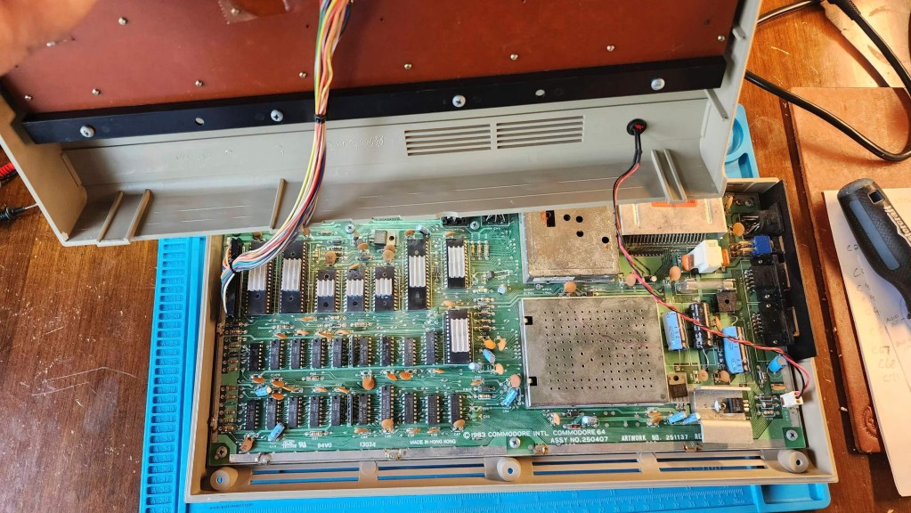
Commodore 64 (ASSY NO. 256407)
Years (1982-1993)
Interesting Fact: When the C64 was launched, it was targeted at the home consumer and unlike its competitors, was more powerful, cheaper, and could be purchased from department stores, toy stores, and discount retailers. (source) It became the most popular home computer ever, making “instant geeks out of millions of people back in the 80s.” (source) Total sales during its production were close to 17 million with 10,000 commercial software titles developed. (source) In short, it was a runaway hit, costing $595 USD at its release and then dropping to $149 USD by 1985. (source)
For a detailed insight into Jack Tremiel and the founding of Commodore, watch the documentary, The Commodore Story by Steven Fletcher.
Condition When Acquired: Fully Functional
Current Condition: Fully Functional


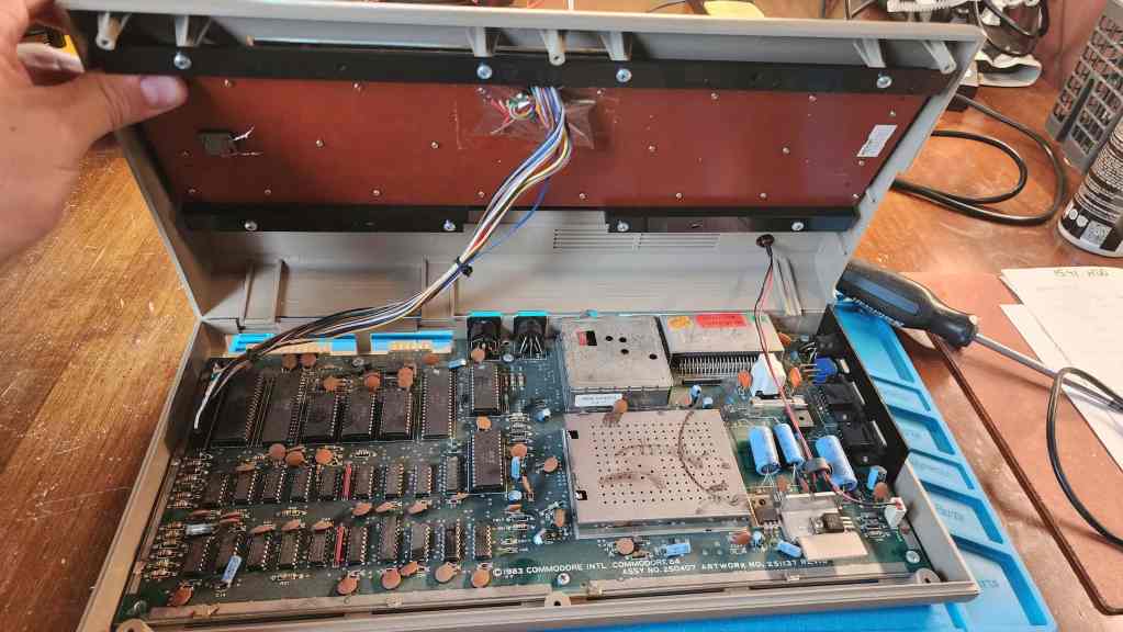


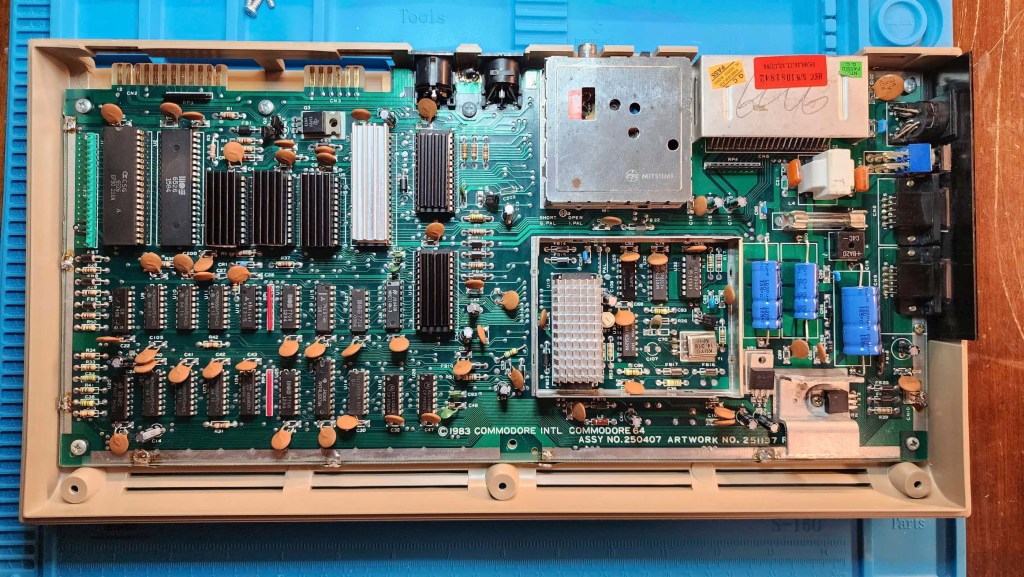


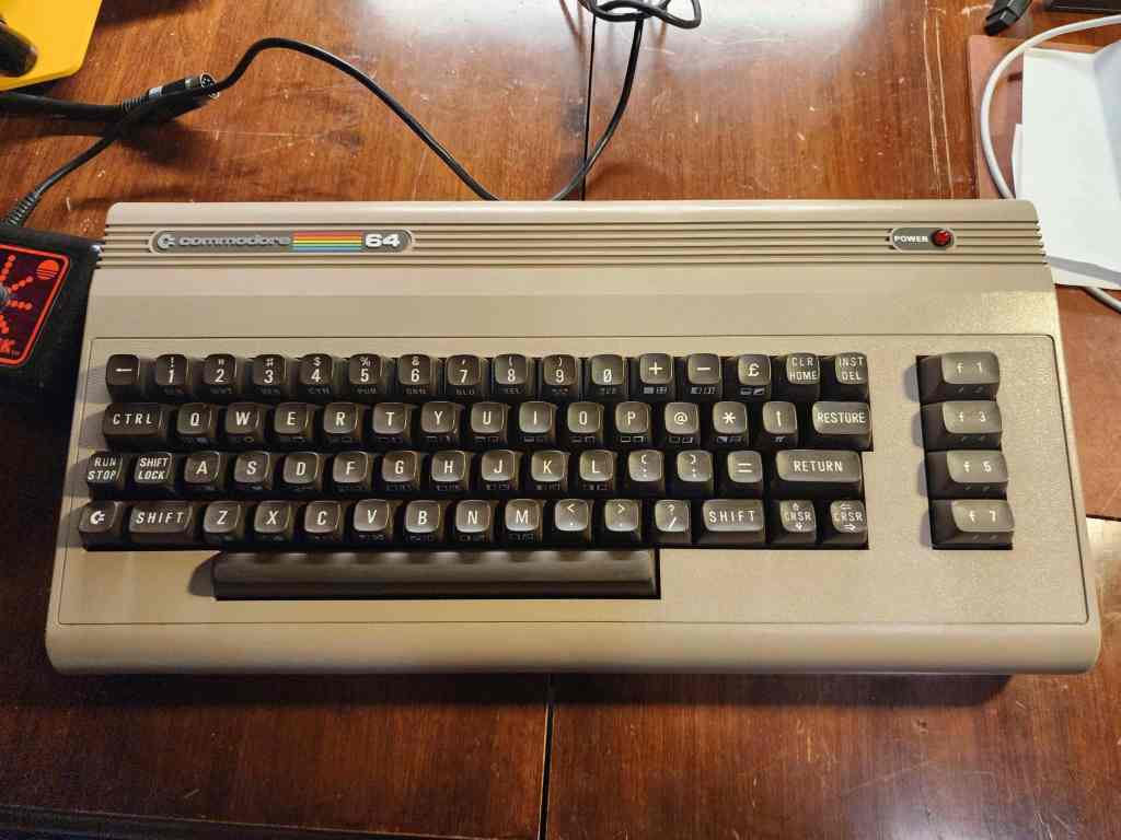
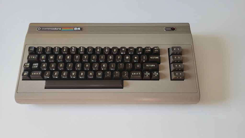
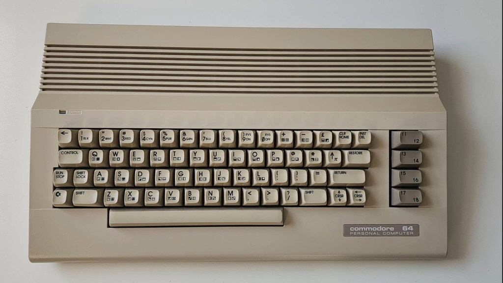
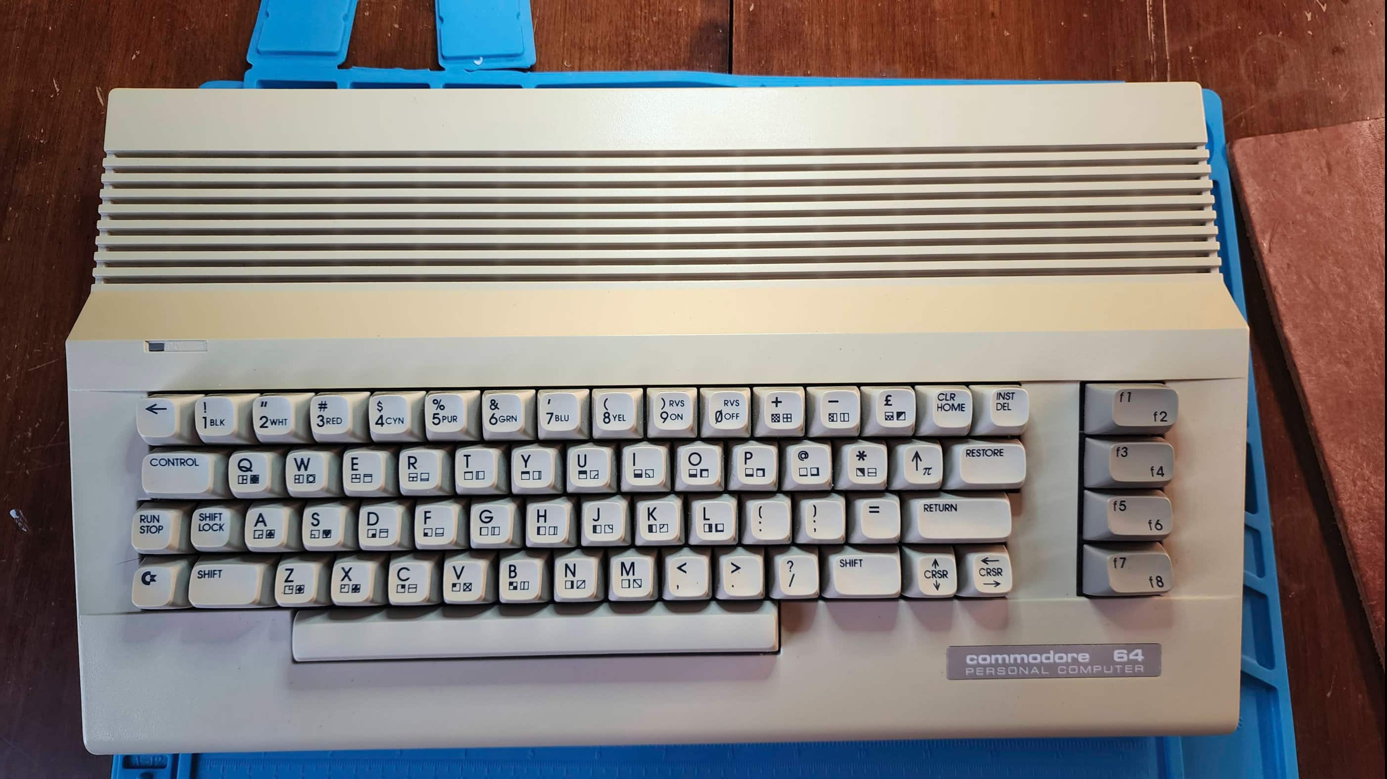
Project Details: Okay! I lucked out on another working C64. This one is a later model than my REV A board and I believe it is probably the same revision that my original 1983 C64 was. The first thing I noticed after unboxing, was that it had a band of yellowing on the back of the machine. Some of the keys were also a bit yellow, but all in all, it wasn’t too bad.
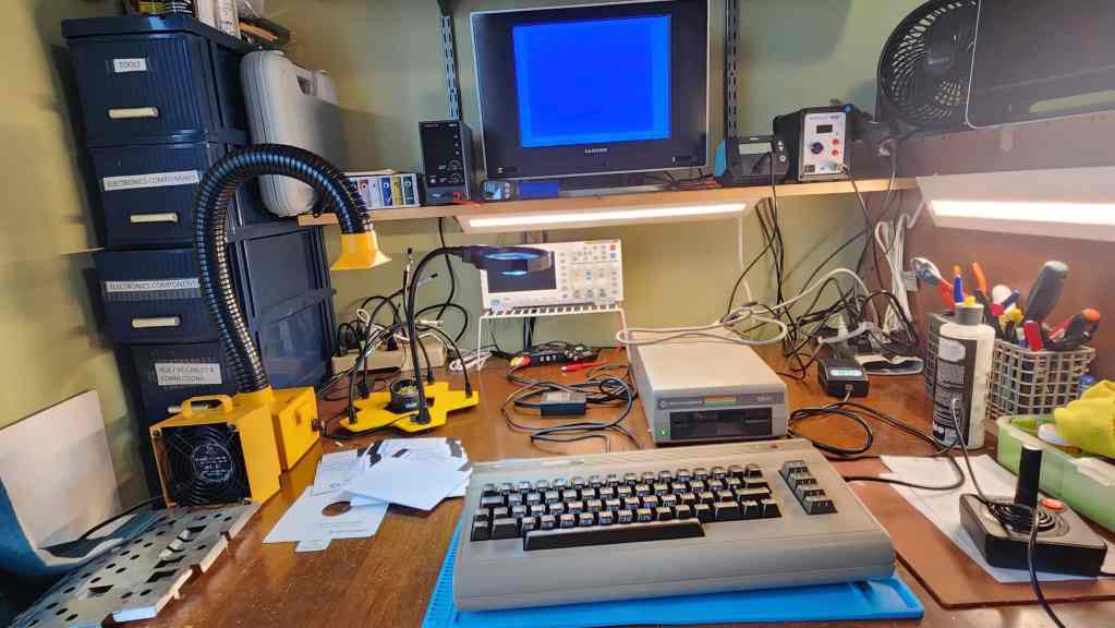
As I did with my last C64, I did not power it on with the OEM PSU, but instead used my Keelog PSU (in fact, after I was done with the machine, I ordered in another one). I also used the 5 pin DIN composite cable that I cobbled together for my REV A board. Though the 250407 revision outputs luma and chroma as well as composite, for testing purposes, composite was just fine. I have a 1702 monitor cable, but I don’t have the monitor, so someday I will build an s-video cable if I can’t track down a monitor. However, to be honest, the composite signal looks really good, but I’m also a Gen X’er so my eyes are probably going bad.
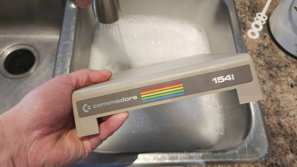
My first test of the unit proved that it was indeed, fully working. I further validated this by running it through a testing harness after I had opened it up. I then hooked up a working 1541 drive that I purchased last year, and loaded some games. Everything worked as it should. As a side note, the 1541 was my Christmas present in 1984.
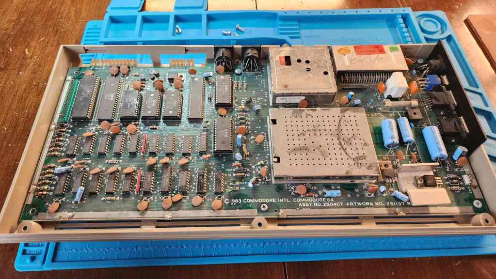
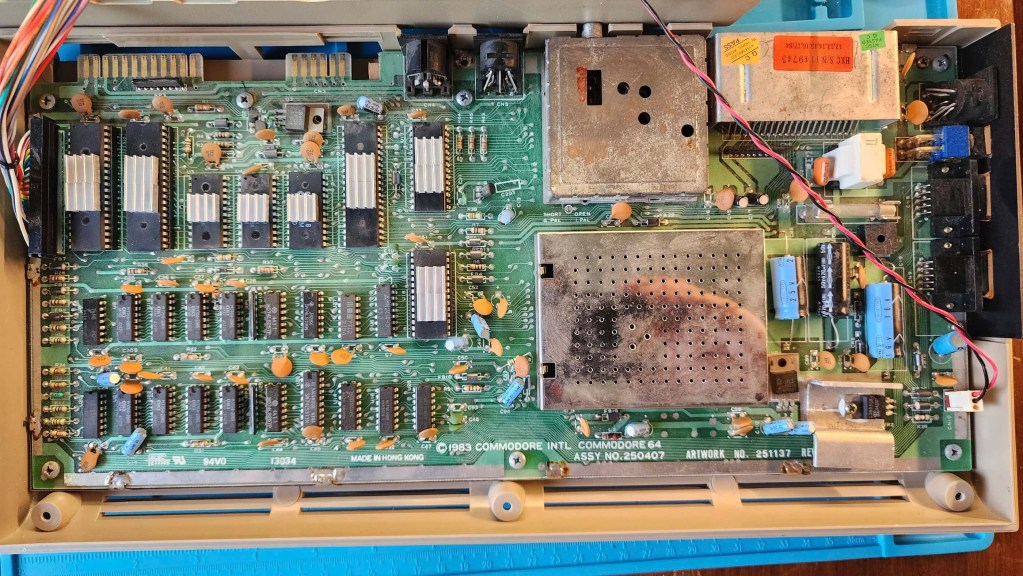
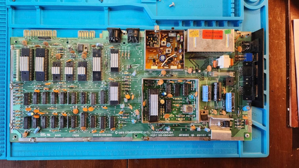
Inside, the machine had a thick layer of dust and grime, but unlike my REV A board, no capacitors were on backwards. In fact, in this revision, Commodore had changed the location of the 7805 voltage regulator and had paired it with a larger and much beefier heatsink.
After a good cleaning that included reseating all the socketed chips, I did what I previously said that I try to avoid unless necessary: re-capping for the sake of re-capping. I’ve debated this internally over the past few projects and after reading lots of good information for and against, I’ve elected to go with my gut when it comes to 40+ year-old capacitors (and anything from the 90s). Yes, eventually they will fail, but that could still be another 10 or more years from now; however, for some of my recent geriatric units, I’ve decided to err on the side of caution, especially ones that have sensitive power needs or ones with heat issues. Hence, I’ve chosen to re-cap but only with the highest quality modern equivalents that I can find.
So, with this ongoing inner dialogue, I chose to re-cap this unit as well as replace the 7812 and 7805 voltage regulators. What I didn’t do though – and it was a gut decision – was to de-solder the RF modulator and re-cap that. I left that as stock.
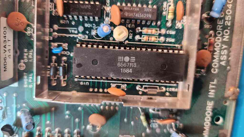
I then put new heatsinks on the R8 VIC-II, PLA, SID, 6502, and ROMs. For the VICII, I used the other half of the Nvidia Geforce 64 heatsink that I cut to fit my REV A board. In this case, I simply removed the RF box lid and kept it off.
A cleaning and polishing of the case and keyboard followed before testing where everything worked fantastically. As my 1541 needed a bit of TLC, I opened it up for an inspection. After I cleared out the dust, I cleaned the read/write head, made sure belt was in good shape, and then recapped the main board. I may also return to remove and apply new thermal paste to the 7812 and 7805 TO-3 regulators.
Once the drive and computer were back together, I then decided to make a new composite cable to go with either this C64 or the REV A model.
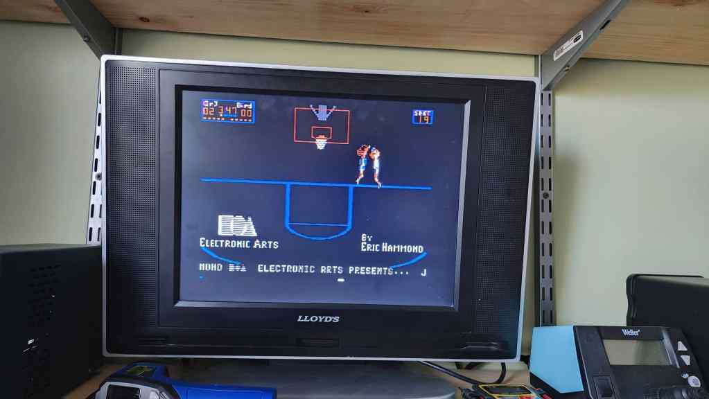
Since I’ve completed this work, I’ve spent a long time playing on this unit. It definitely has brought back the memories, including another game that I used to play with my best friend, Jason – One On One featuring Dr. J and Larry Bird. This 41-year-old EA game is still fun! I’ve also enjoyed a pile of other games including Spy Hunter, Jumpman Jr., H.E.R.O., and of course, Bruce Lee.
I didn’t think that getting these C64s would trigger this much nostalgia, but since the computer is tied to two people who have passed away, it amplifies things a bit.
Parts & Products Used: 99% isopropyl alcohol; Chemical Guys Natural Shine; Deoxit D5; electrolytic capacitors (radial) – 16v 100μF (1); 25v 10μF (13); electrolytic capacitors (axial) – 16v 2200μF (1); 25v 470μF (1); 25v 1000μF (1) 7805 voltage regulator; 7812 voltage regulator; heatsinks; thermal paste; Keelog C64 power supply. 1541 Floppy Drive: electrolytic capacitors (radial) – 10v 220μF (1); 16v 47μF (2); 25v 1μF (2); electrolytic capacitors (axial) – 16v 4700μF (1); 25v 6800μF (1)
Commodore 64 (ASSY NO. 256407)
Years (1982-1993)
Interesting Fact: When it was in development, the C64 was called the, “VIC-40” by Commodore engineers and in the six weeks after Jack Tramiel announced its development, the Commodore team was able to produce five VIC-40 prototypes. (source) This was due in part because Commodore owned MOS Technologies and could build and test its own chips. (source)
Condition When Acquired: Partially Functional
Current Condition: Fully Functional

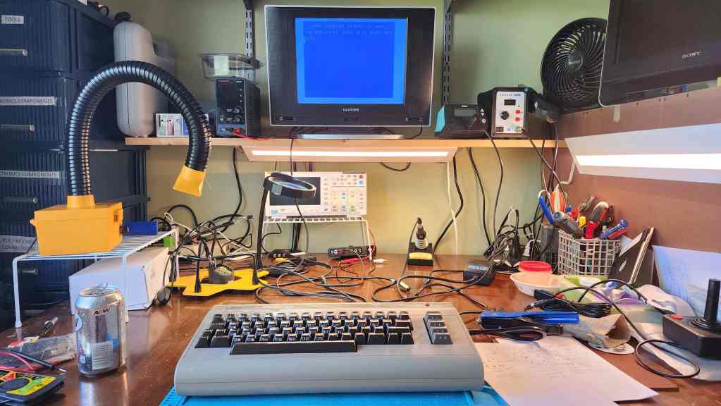


Project Details: I seem to be collecting C64s on a more frequent basis, which is fine by me. 🙂 This unit came to me with a broken power button but in otherwise, working condition. Separately, but at the same time, I also received another 1541 5.25” floppy disk drive, so I decided to work on them at the same time.
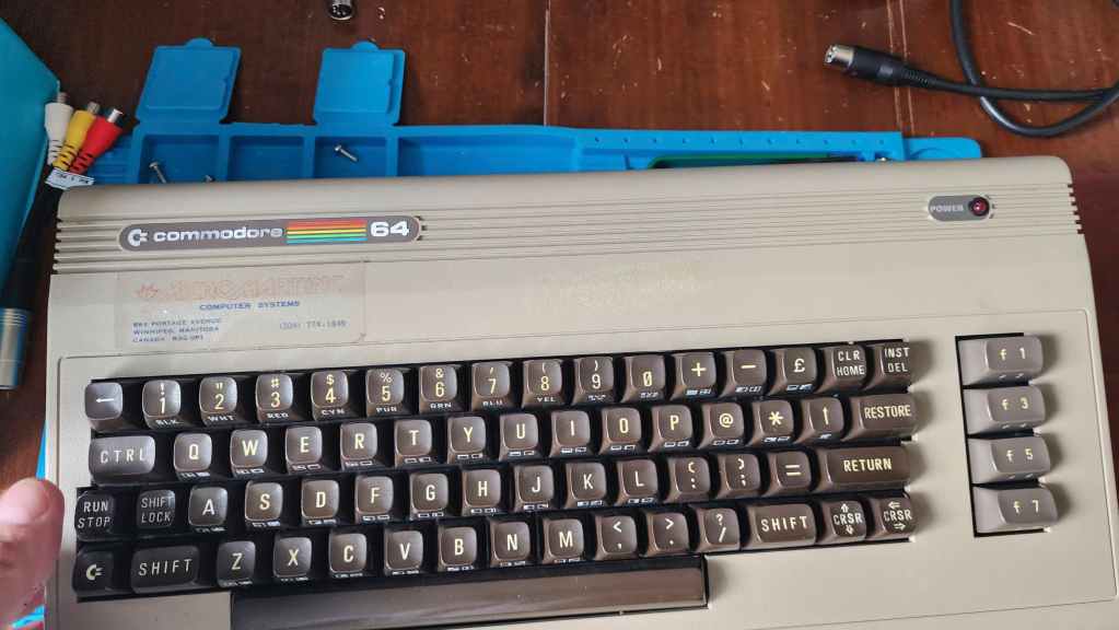
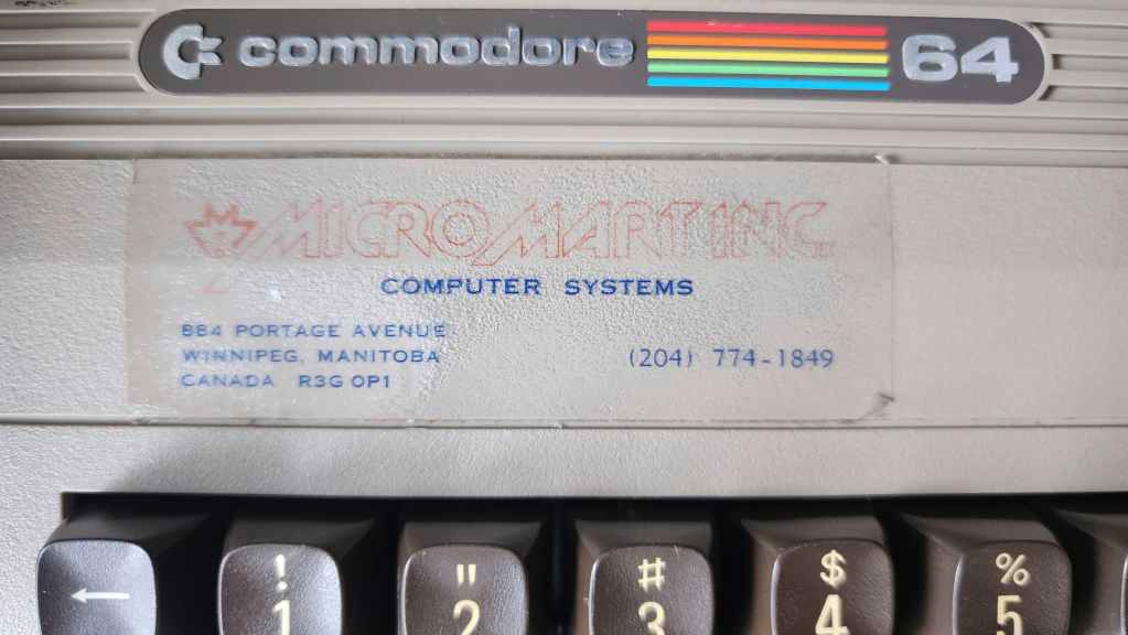
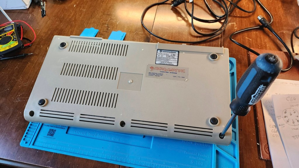
What I found interesting, was that the C64 had ‘Micro Mart Inc. Computer Systems’ decals on both the top and bottom of the case. I assume that Micro Mart was a Winnipeg based computer store (884 Portage Ave) and this might have been a demo unit that they used in the store. When I opened it up, all of the chips had heatsinks installed, so this furthered my suspicion that it was a demo / test machine. Also of note, is that this is another C64 that was made in Canada.
After an initial inspection, I could see that the power switch was not salvageable. Though it could turn the machine on, it could sometimes take several attempts to get there. Before diving into fixing the switch, I was able to hook it up to the diagnostic harness and run it through a quick test where everything came back as good. I also noted that the memory was OKI and not MT, so that also was good news, as MT DRAM can be failure prone.
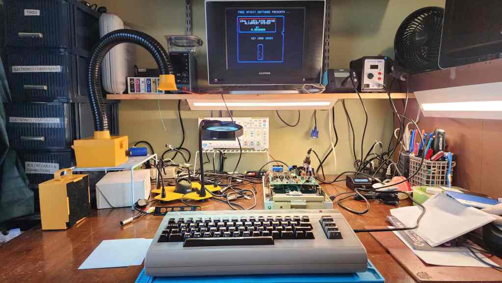
Before beginning, I also took the time to build a new C64 S-video cable using Jan Beta’s tutorial. It worked perfectly; though I would later acquire a working Commodore 1802 monitor, so now at least, I have the best of both options. I am keeping my eye for a 1702 however…
As I have a C64 that I use as a parts machine, I was able to use its power switch on the new C64. It was a simple matter to desolder both switches and then solder the replacement one onto the new C64. After this was done, I then retested the machine and noted that it now turned on perfectly and that all the diagnostics were still normal as well.
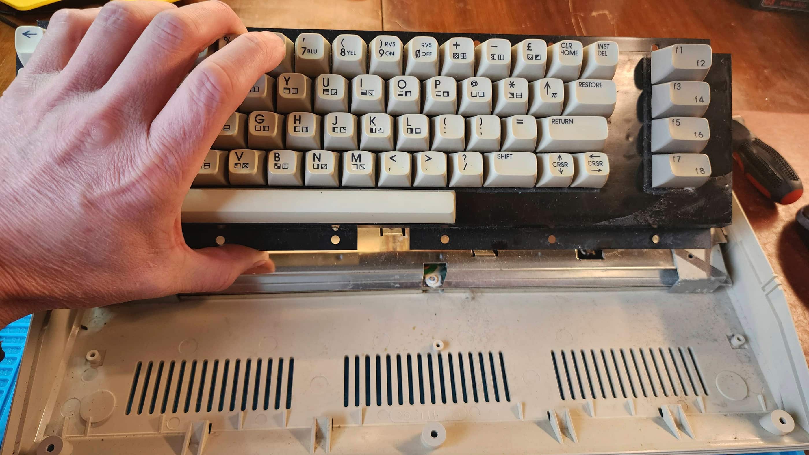
I then gave the board a thorough cleaning with IPA and reseated and treated all the socketed chips with Deoxit D5. I then removed and cleaned the keyboard and the both halves of the case. When I was taking the unit apart, I also noted a broken stand post on the front of the bottom case, so after it was washed, I used Permetex Plastic Welder to fix the post. I also tried to get as much rust off the RF shielding as I could.
Finally, I re-capped the entire board, replaced the 7812 and 7805 voltage regulators, and paired it with a new Keelog C64 power supply, as I never use the old bricks even if they test okay. It then put everything back together and once again, used the diagnostic harness for testing. Everything worked perfectly and the newly cleaned machine looked good too.
Next, I moved on to the new 1541 drive. The person I received it from, told me that he had built it from two different drives almost 30 years ago, hence the difference in yellowing between the case and the ALPS faceplate.
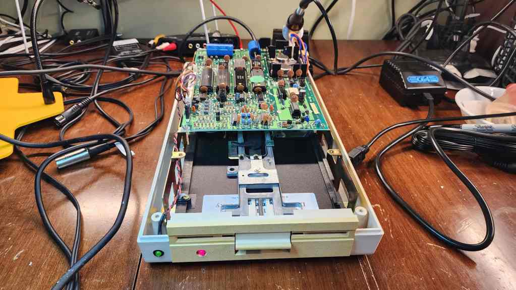
The nice thing was the drive worked and so this was a pleasant surprise. On opening it up, I noted that it was quite dirty and more concerning, capacitor C17 had started to leak, so that would be my first fix. Again, if I’m going to replace one capacitor, I may as well replace them all, so that’s what I did. I also reseated and treated all socketed chips with Deoxit D5.
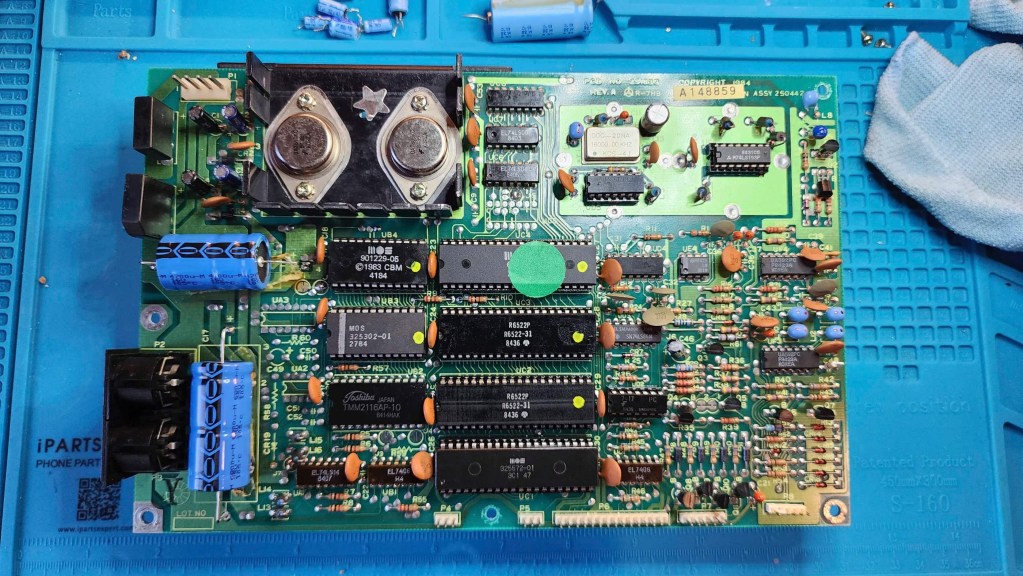
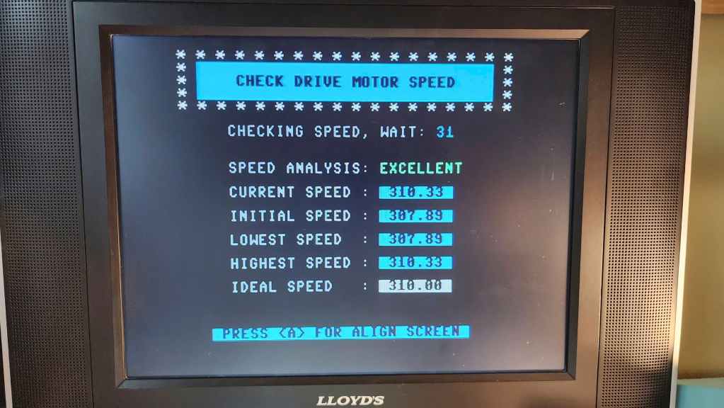
After cleaning the board and case, I proceed to test the drive including with realignment software. Everything was up to spec and was working as it should. I now have another wonderful working C64 and 1541 as part of my collection.
Parts & Products Used: 99% isopropyl alcohol; Chemical Guys Natural Shine; Deoxit D5; electrolytic capacitors (radial) – 16v 100μF (1); 25v 10μF (13); electrolytic capacitors (axial) – 16v 2200μF (1); 25v 470μF (1); 25v 1000μF (1) 7805 voltage regulator; 7812 voltage regulator; heatsinks; thermal paste; Keelog C64 power supply. 1541 Floppy Drive: electrolytic capacitors (radial) – 10v 220μF (1); 16v 47μF (2); 25v 1μF (2); electrolytic capacitors (axial) – 16v 4700μF (1); 25v 6800μF (1)
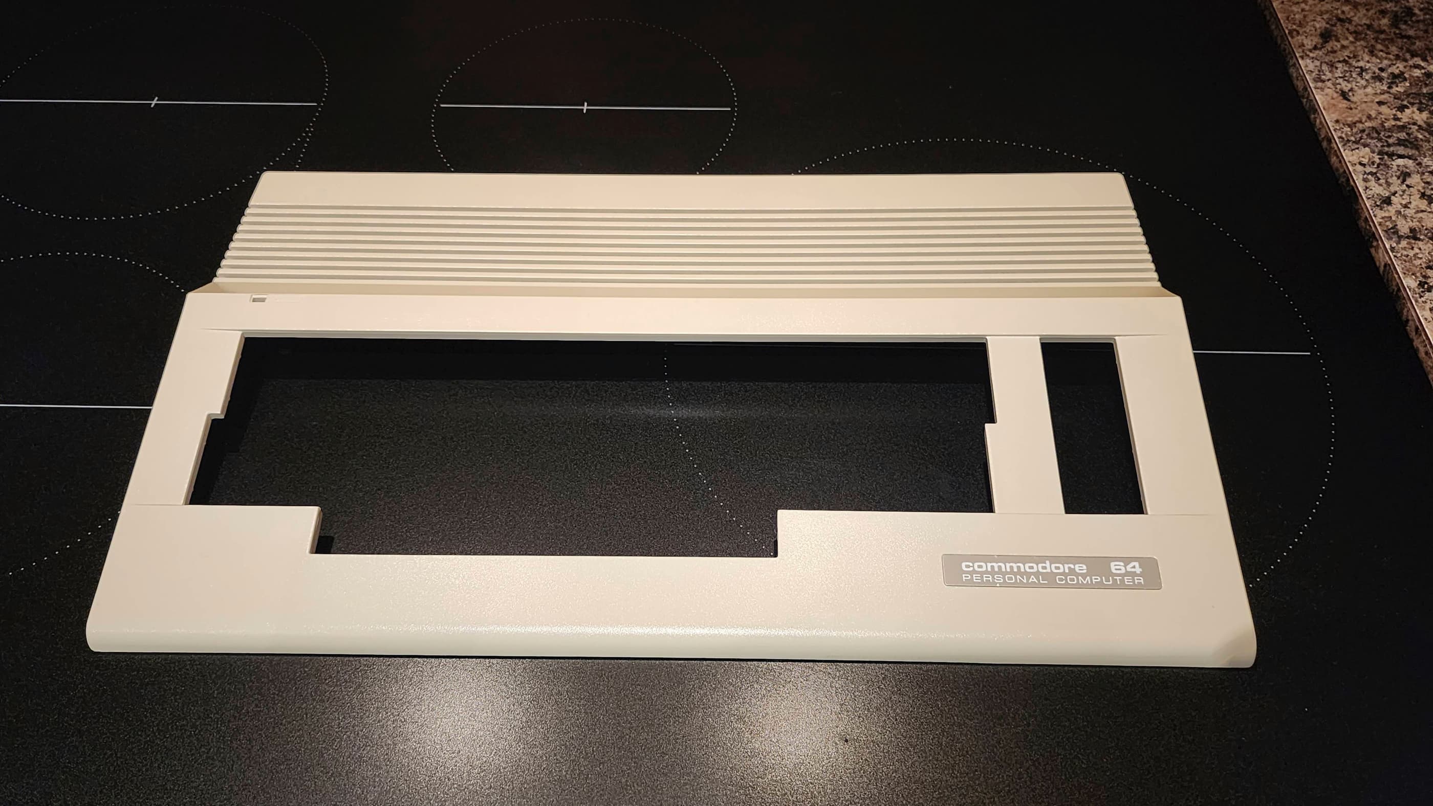
Commodore 64C
Years (1986-1993)
Interesting Fact: The C64C was a redesign of the original C64. Released in 1986 with colour and styling to match the new C128, the 64C also featured several cost-cutting measures. (source) For example, the 41464 DRAM was consolidated from 8 chips to only 2, and the PLA chip and the colour RAM was integrated into the ASIC chip. (source) The mainboard was also pared back (hence, the nickname ‘short board’) and the PETSCII graphics were printed on the top of the keys instead of the side, to save production costs. Also notable, was the redesign of the SID chip to use less voltage and new sound filters. (source)
Condition When Acquired: Fully Functional
Current Condition: Fully Functional


Project Details: This C64C came to me as an untested unit. However, a quick power test (not using the stock PSU) showed that it was fully functional. It was badly yellowed, but everything seemed to be in order.
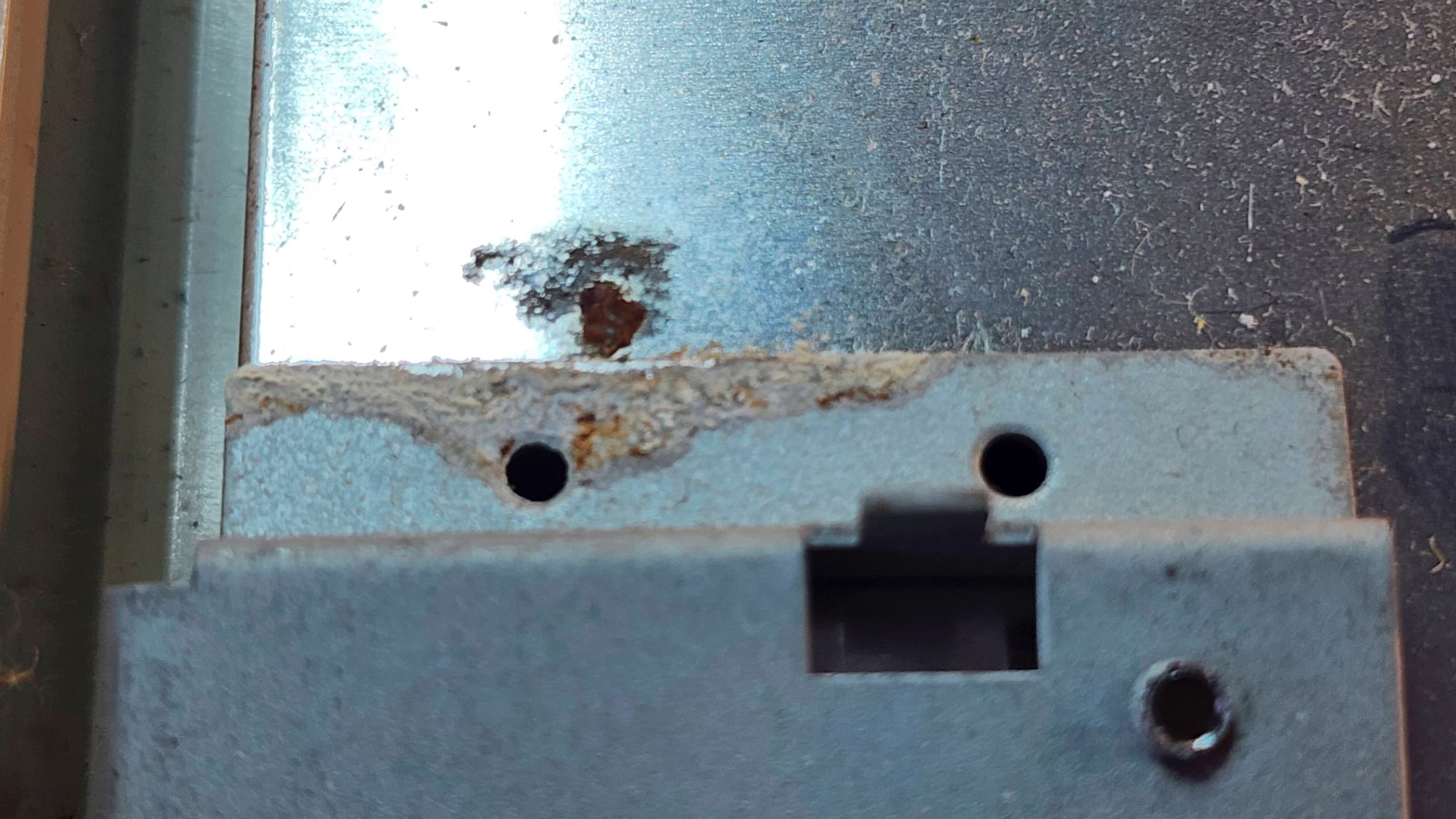
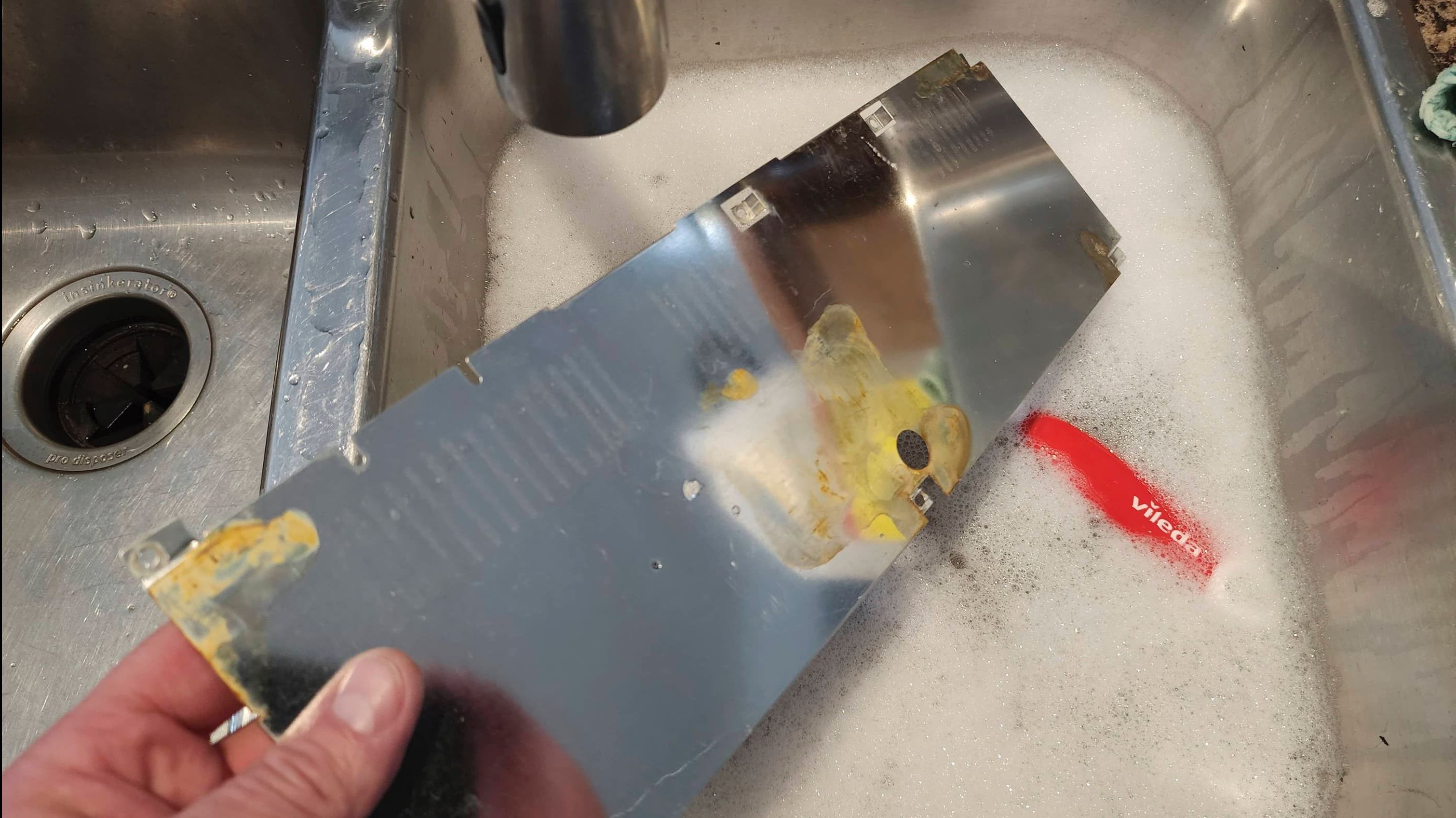
On opening the case and removing the RF shielding, I was surprised to see a ton of rust on the board. Removing the bottom case revealed a large rust stain in the plastic and then removing the bottom RF shielding showed more water damage with a mouldy cardboard liner and another pool of rust. Obviously, this unit had been exposed to a sizeable amount of water at some point in the past and it was remarkable that it still worked. In fact, this would end up being one of the rustiest boards that I’ve ever cleaned.
A quick test using the diagnostic cartridge and harness further validated that everything was working as it should, so the big challenge would be to safely remove the rust. To do this required me to desolder the RF modulator, the metal shielding over the cartridge slot, and both controller ports. It also required a lot of vinegar and sanding on the larger metal areas.
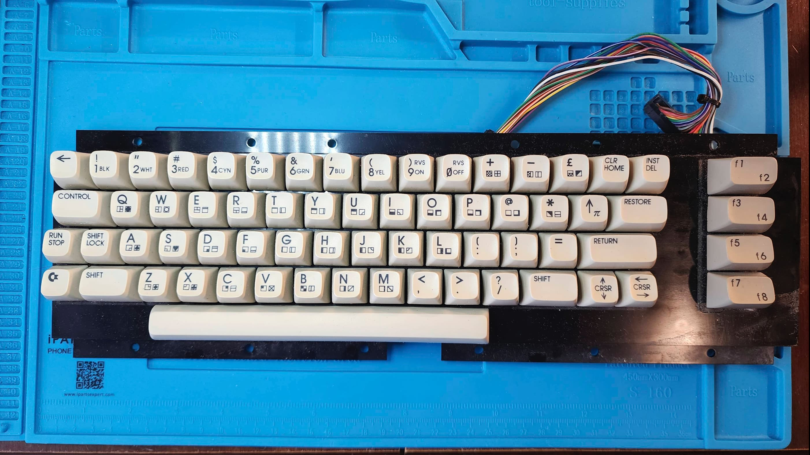
Once everything was as clean as I could get it, I resoldered the parts back onto the board and ran it through another round of diagnostic testing. Everything checked out so I moved on to cleaning the rest of the unit, including reseating all of the socket chips and applying a treatment of Deoxit D5.
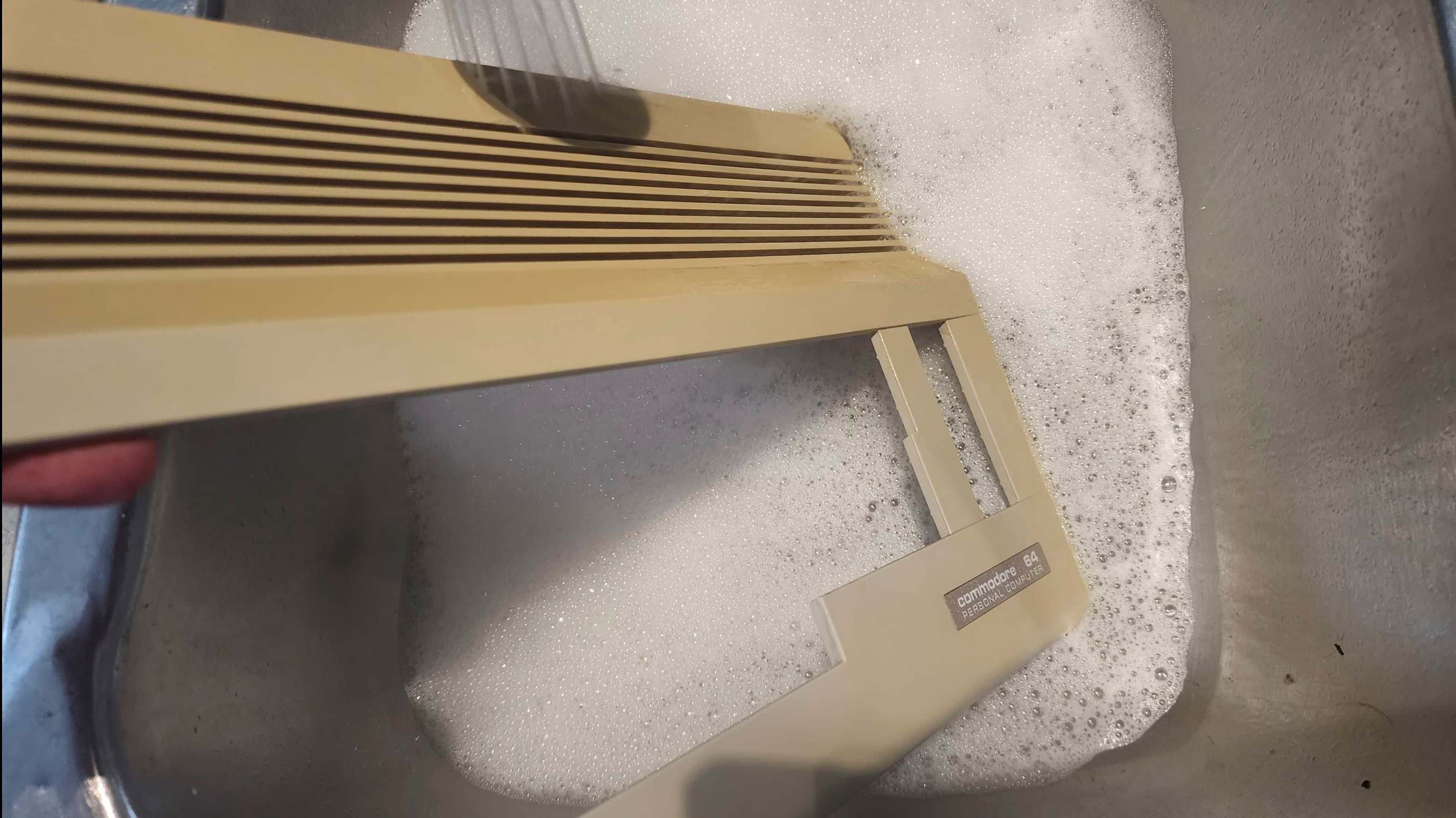
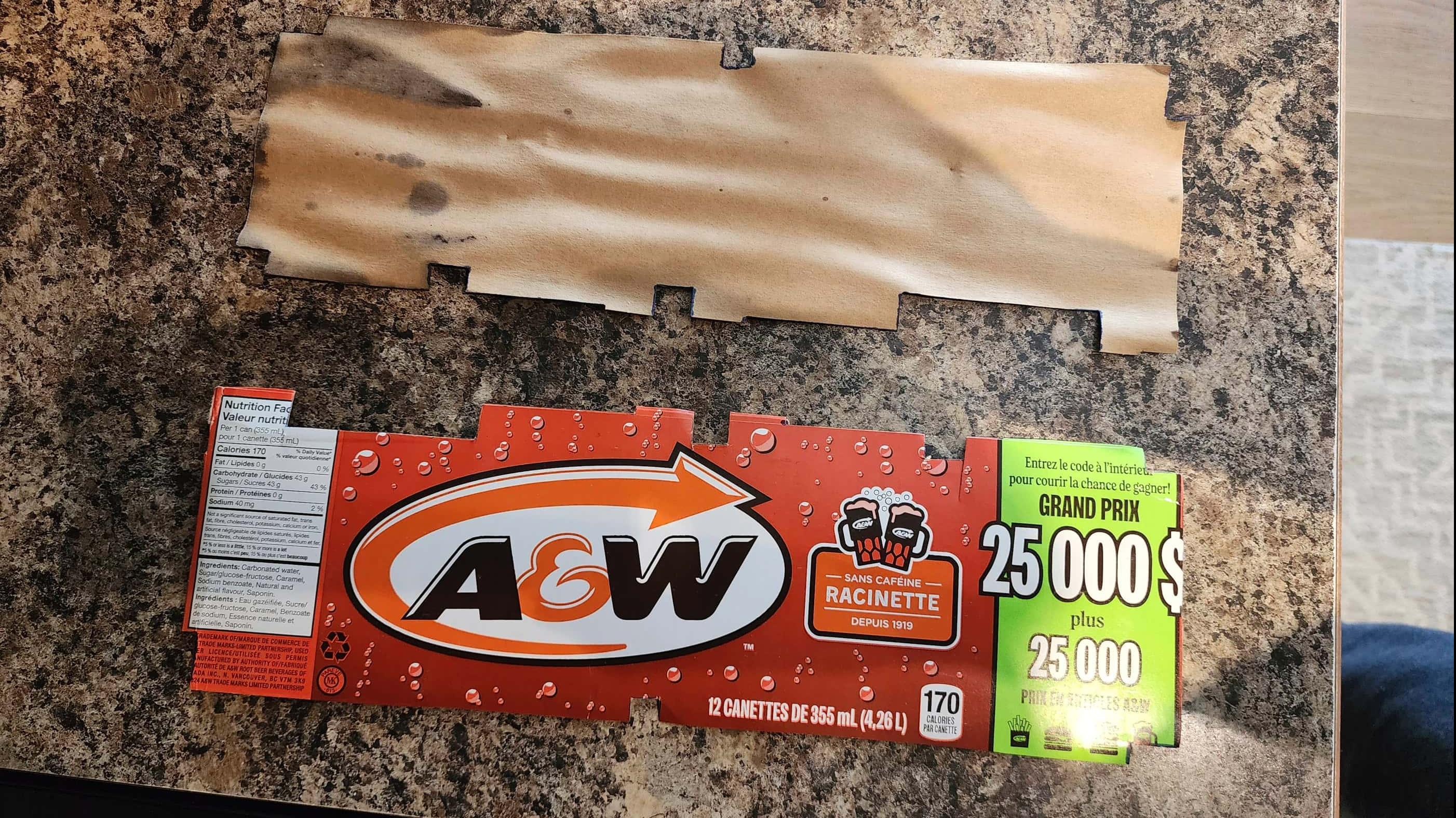
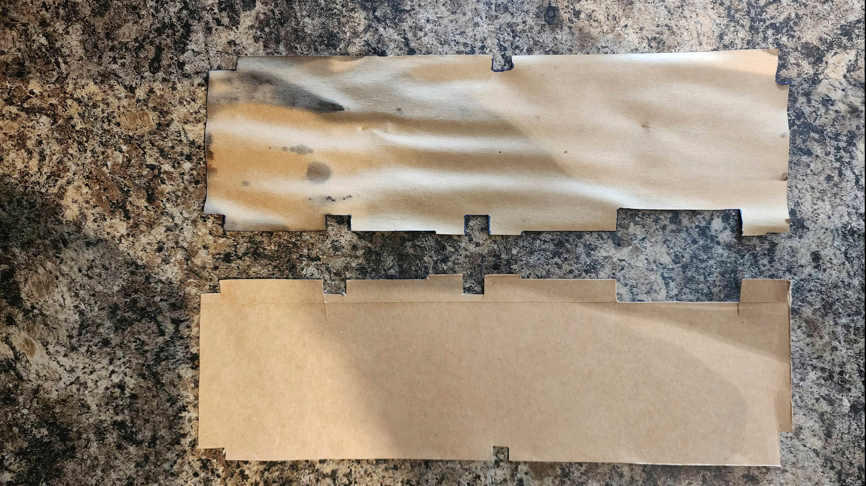
To do this, I disassembled the keyboard and thoroughly washed the keys and the cases. To replace the mouldy liner under the board, I cut out an identical replacement from an old pop can box. Once everything was washed, I retrobrighted the top case to try and bring it back closer to its original colour.
Finally, I put recycled heatsinks onto the main chips, but to make them fit, I had to Frankenstein the RF shielding. 😳 It didn’t look pretty, but the new heatsinks will hopefully prolong the life of the unit.
As this was my first 64C and my first experience with the 8580 SID, I was unsure if its low volume playback of the voice sample in the introduction to Impossible Mission (and other games) was due to its new sound filters or if it was starting to slowly fail. As everything else seemed to be working, I left the chip alone save for the new heatsink.
My last order of business was to swap out the original PSU for a new Keelog one.
Parts & Products Used: 99% isopropyl alcohol; Chemical Guys Natural Shine; Deoxit D5; Keelog PSU; heatsinks

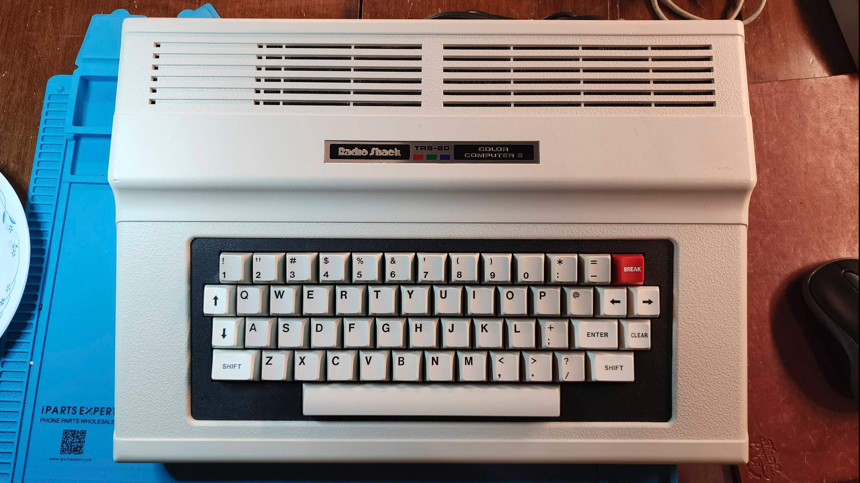
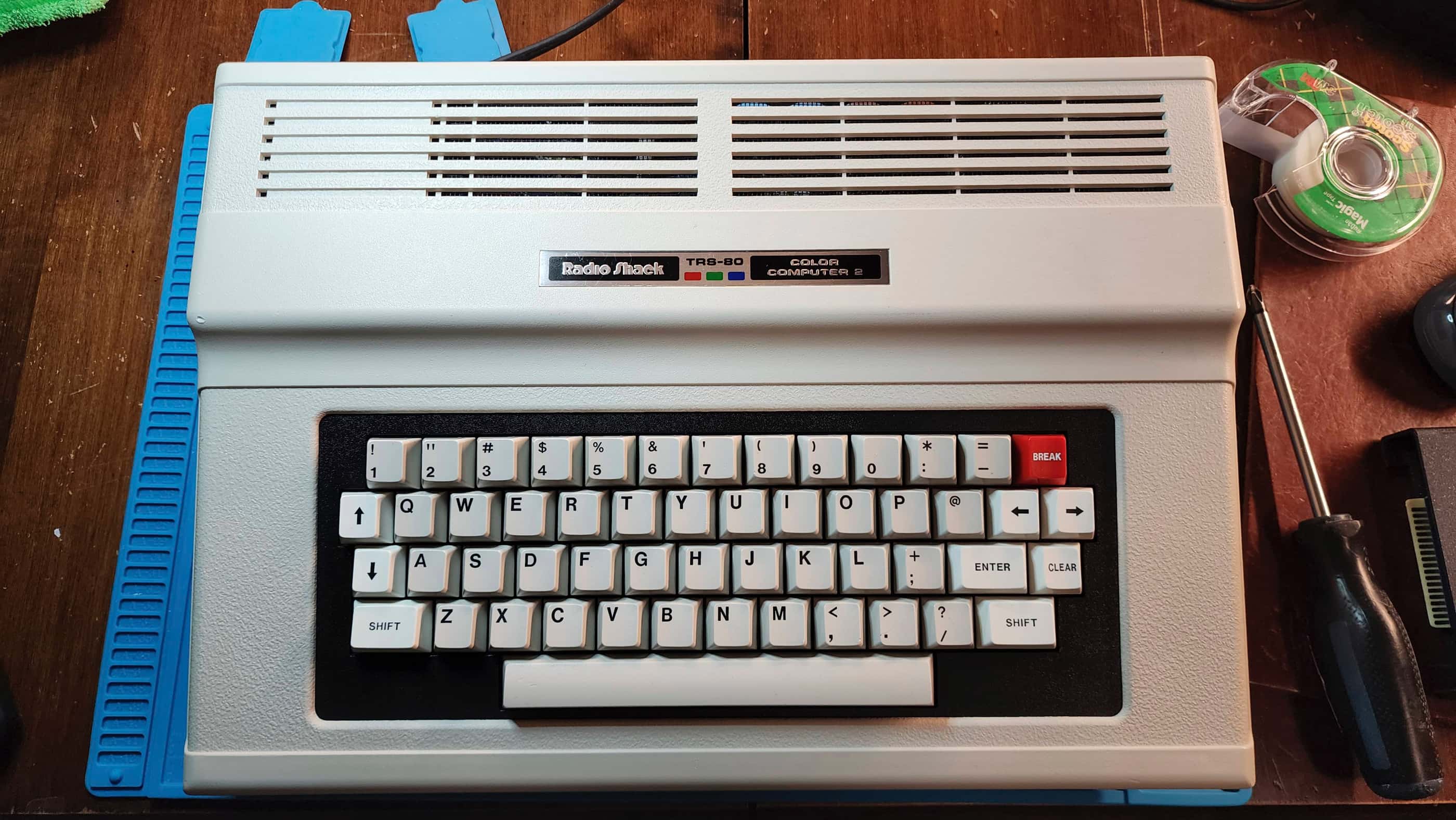
Tandy TRS-80 Color Computer 2 (Model 26-3136A)
Years (1983-1986)
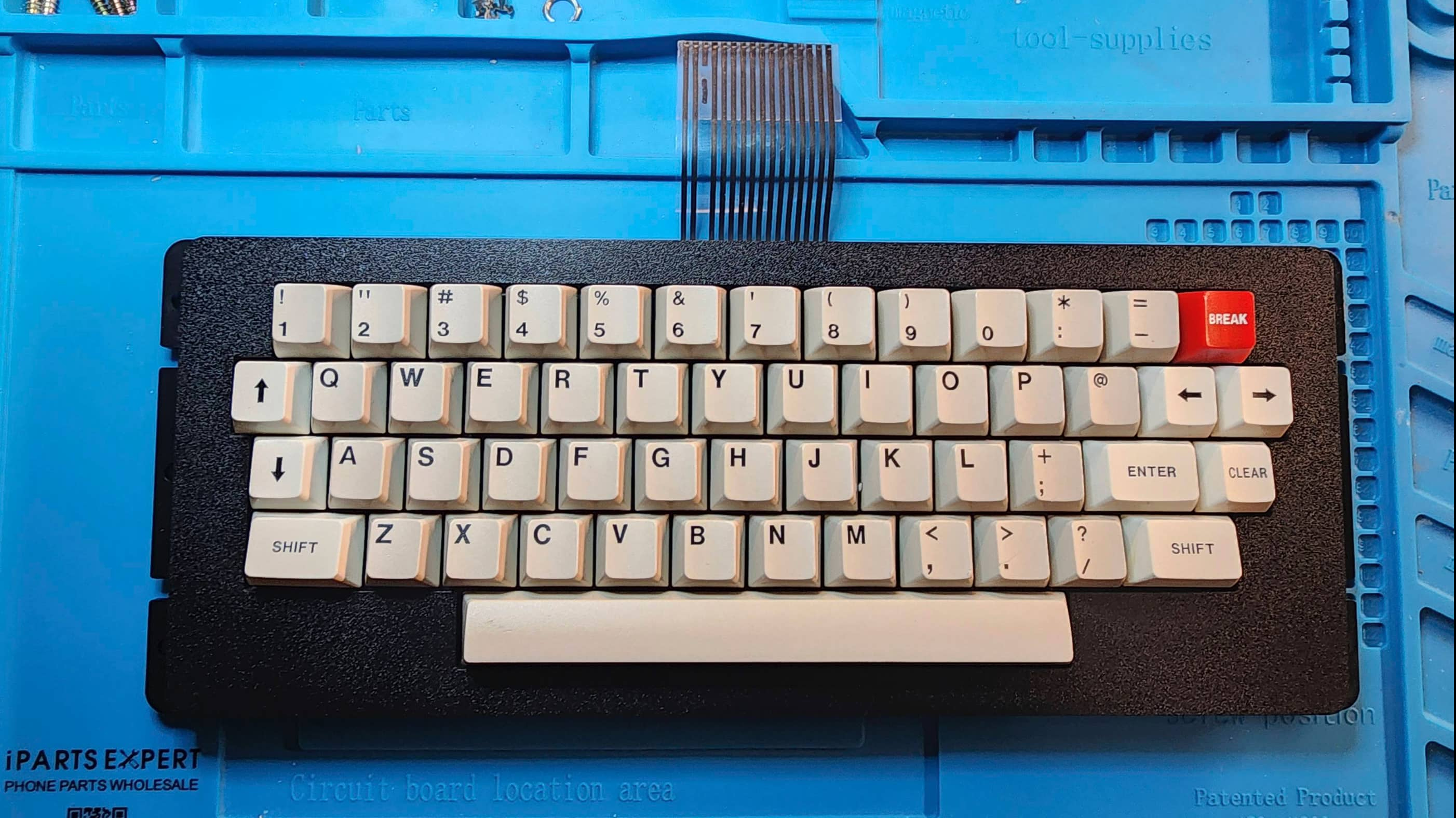
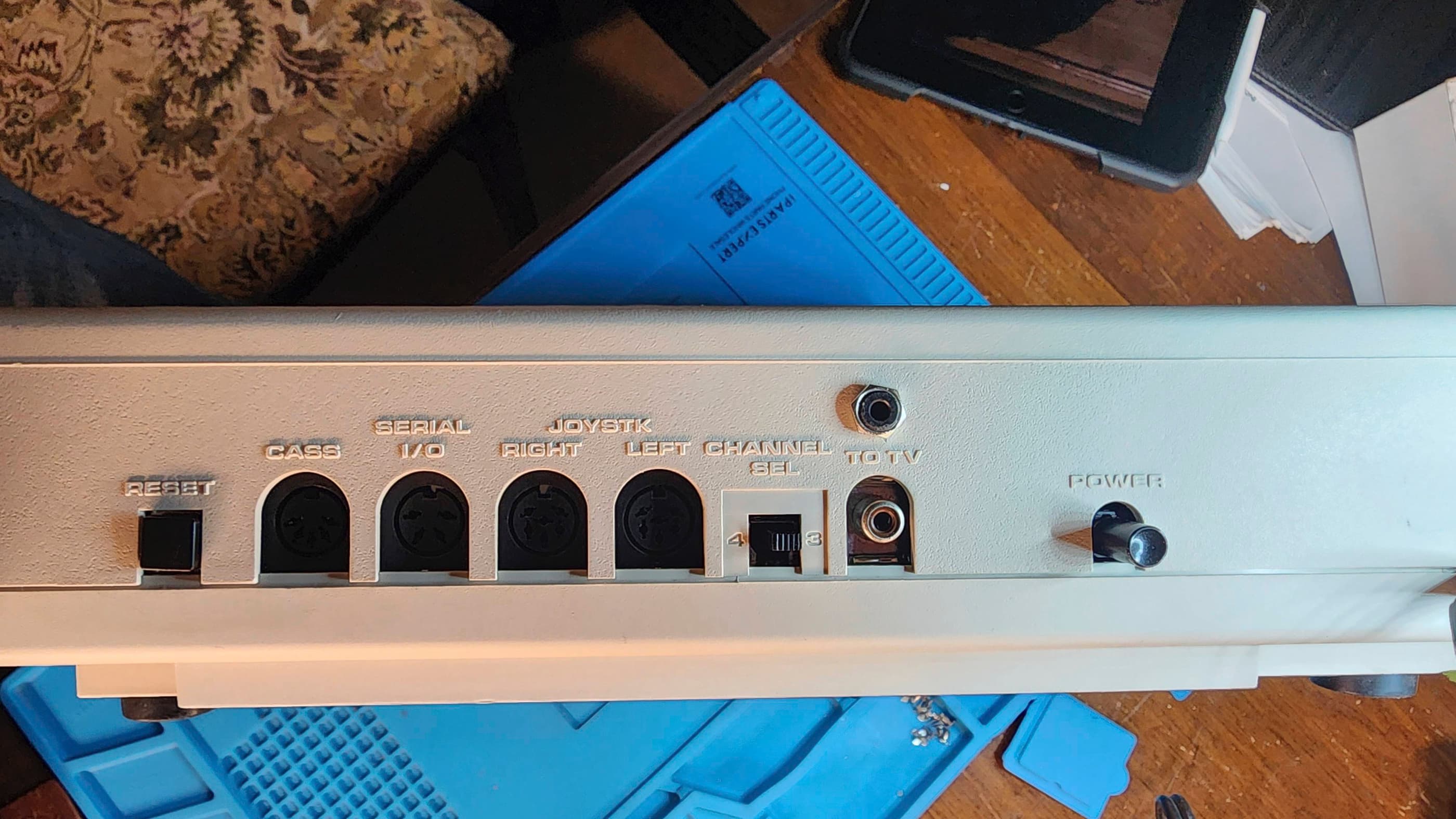
Interesting Fact: The origin of the Tandy Color Computer (CoCo) can be traced back to 1977 when the Tandy Corporation partnered with Motorola to develop a new and affordable home computer that would connect to a TV. (source) The key feature of this new line of computers, was the switch from the Zilog Z-80 processor that was used in the existing TRS-80 business computers to the Motorola 6809. (source) Launched in 1980, the CoCo 1 was replaced by the CoCo 2 in 1983. The CoCo 2 converted much of the discreet circuitry in the CoCo 1 into custom chips that in turn, reduced the size of the original board and case, thereby lowering production costs. (source) Though entirely compatible with the software from the CoCo 1, the CoCo 2 did not include a 12V rail to its expansion slot which made some CoCo 1 peripherals such as the original floppy drive, incompatible. (source) Originally shipped with expandable 16K or 32K of RAM, later models also featured 64K. (source) The CoCo 2 included updated BASIC ROMs, a new custom video chip, and as production progressed, a new full-stroke keyboard. (source) Some CoCo 2s, like this particular unit, were made in Korea. Moreover, at some point in the production cycle, the badging replaced ‘Radio Shack’ with ‘Tandy’.
Condition When Acquired: Partially Functional
Current Condition: Fully Functional


Project Details: Growing up, I didn’t know anyone who owned a Tandy computer. All my friends either had Commodores or Apples. Of course, I knew the Tandy name because Radio Shack remote control tanks and cars were awesome Christmas or birthday presents, but Tandy computers were off my radar.
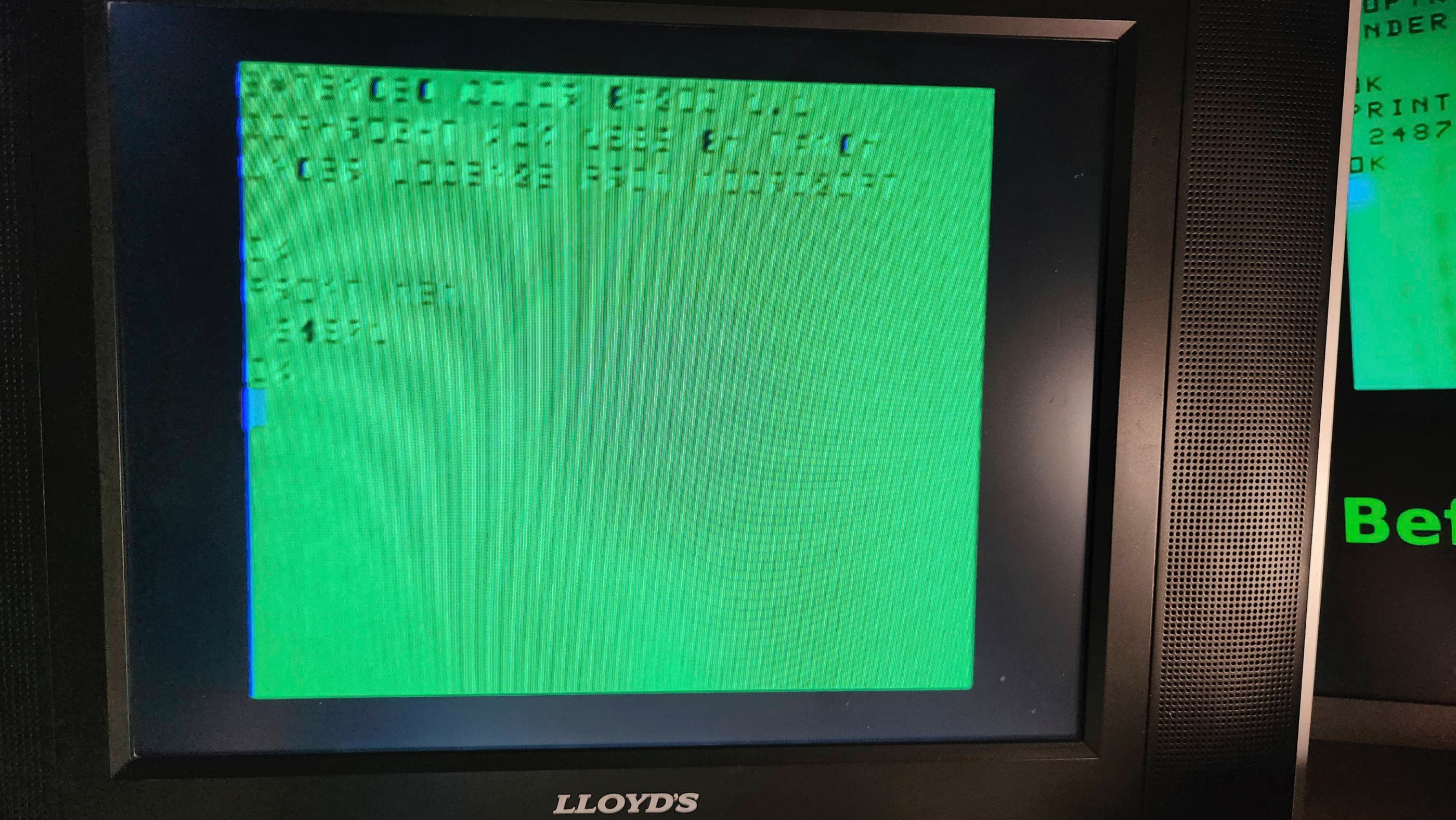
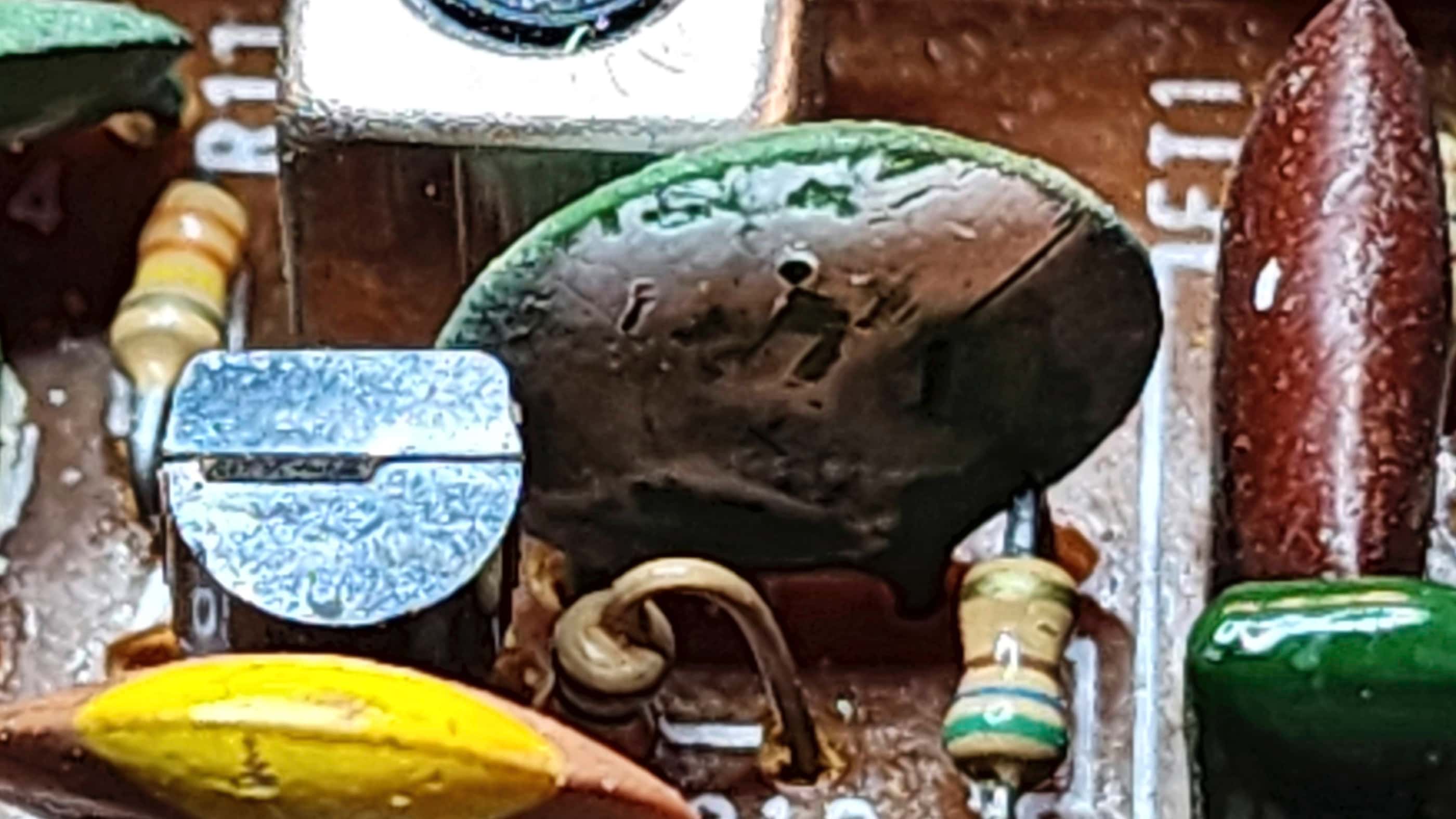
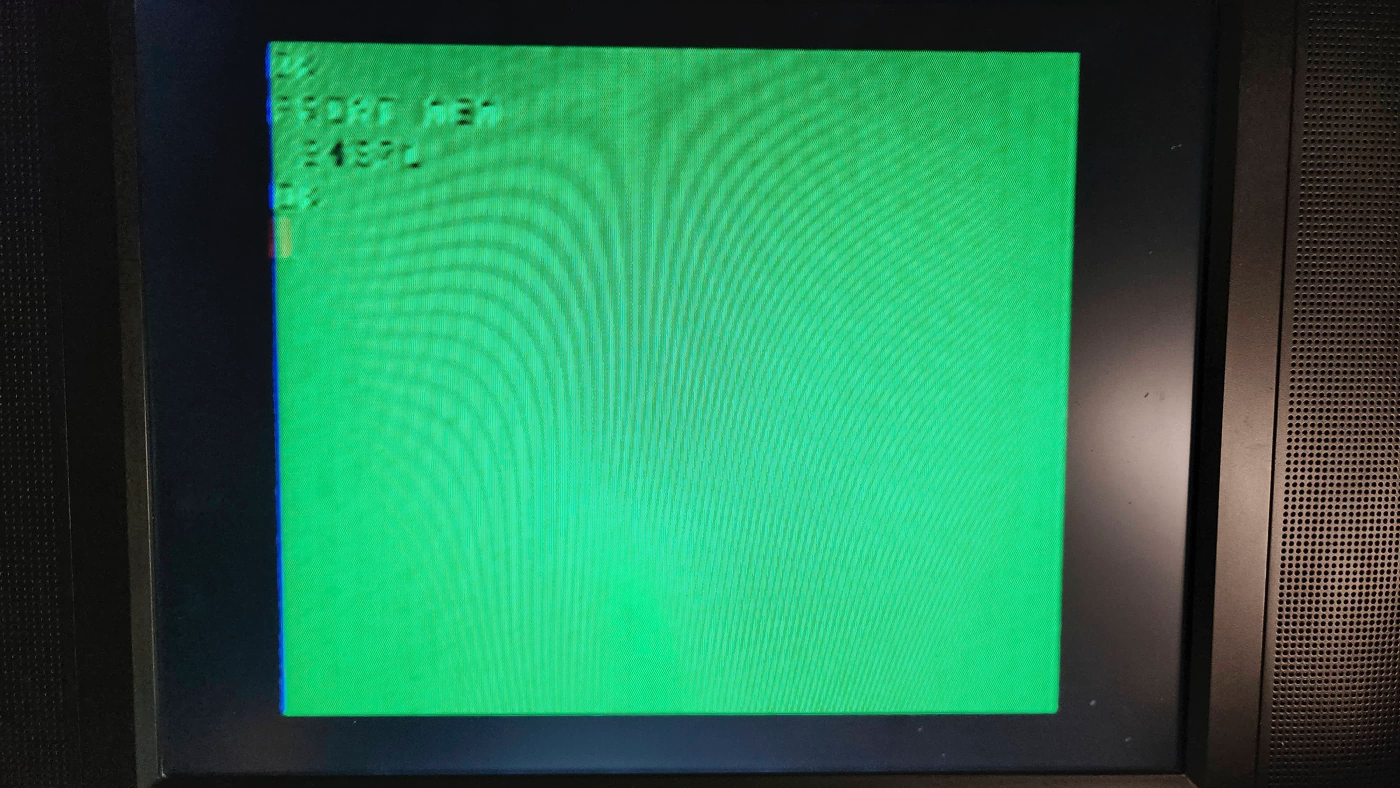
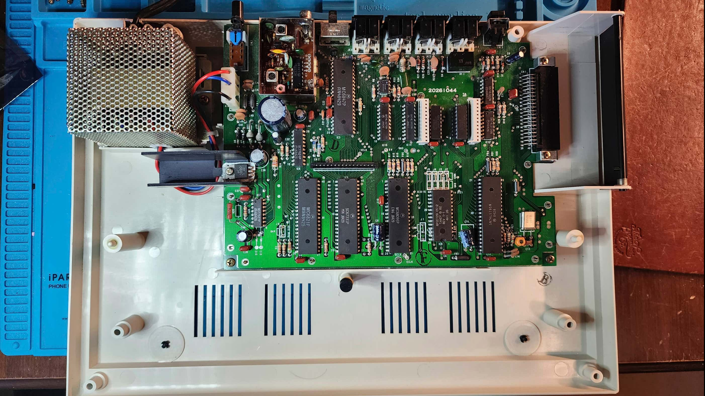
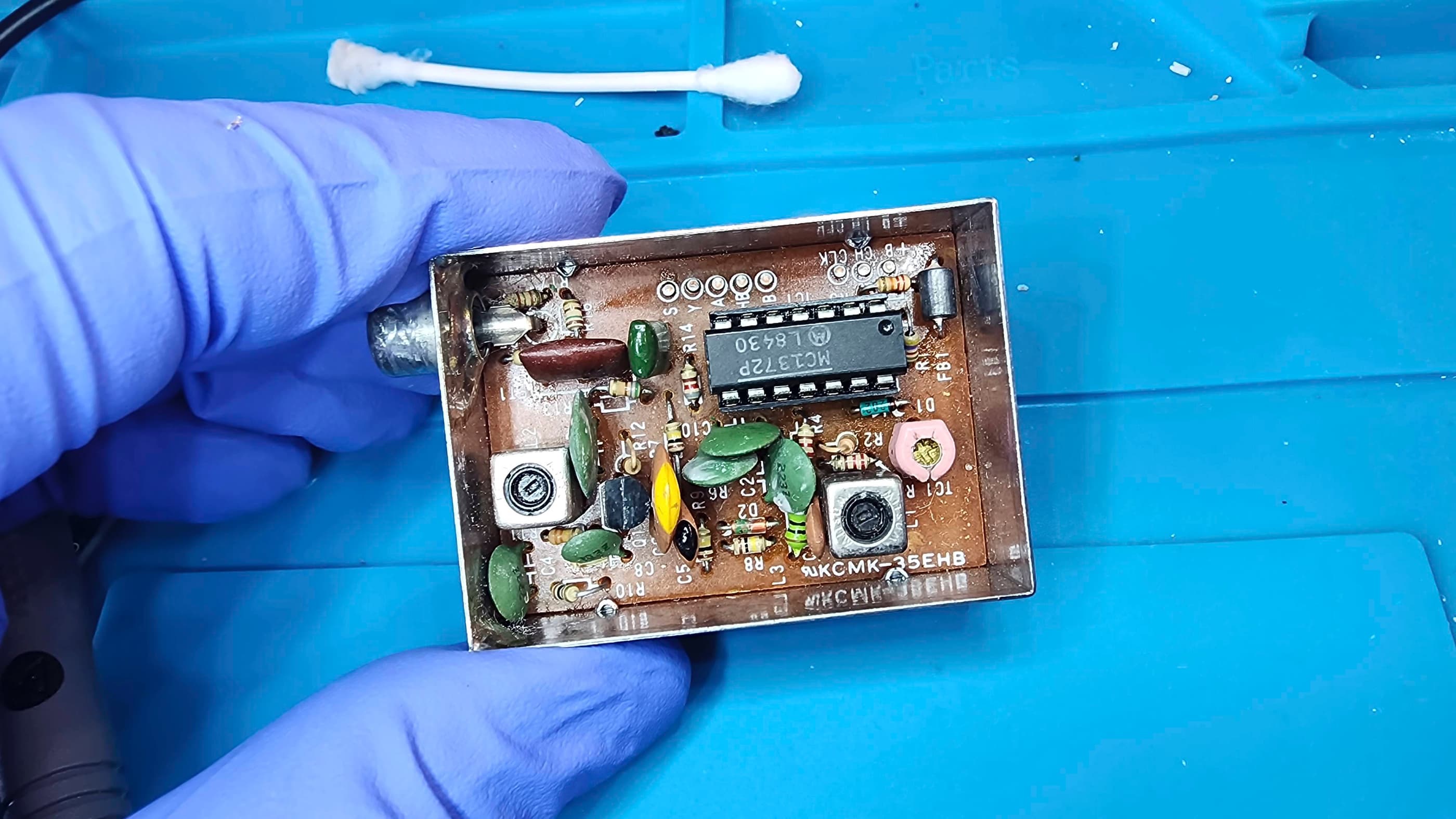
I received this later model, Korean-made, 64K CoCo 2 as a supposedly working computer, so I wasn’t expecting this to be anything more than a deep cleaning project. However, I soon discovered that while it worked, the RF colour output was almost unreadable. On opening the computer, I was happy to see how clean it was, but what I wasn’t keen to see, was the degradation of the green high tolerance (Z) ceramic capacitors in the RF modulator.
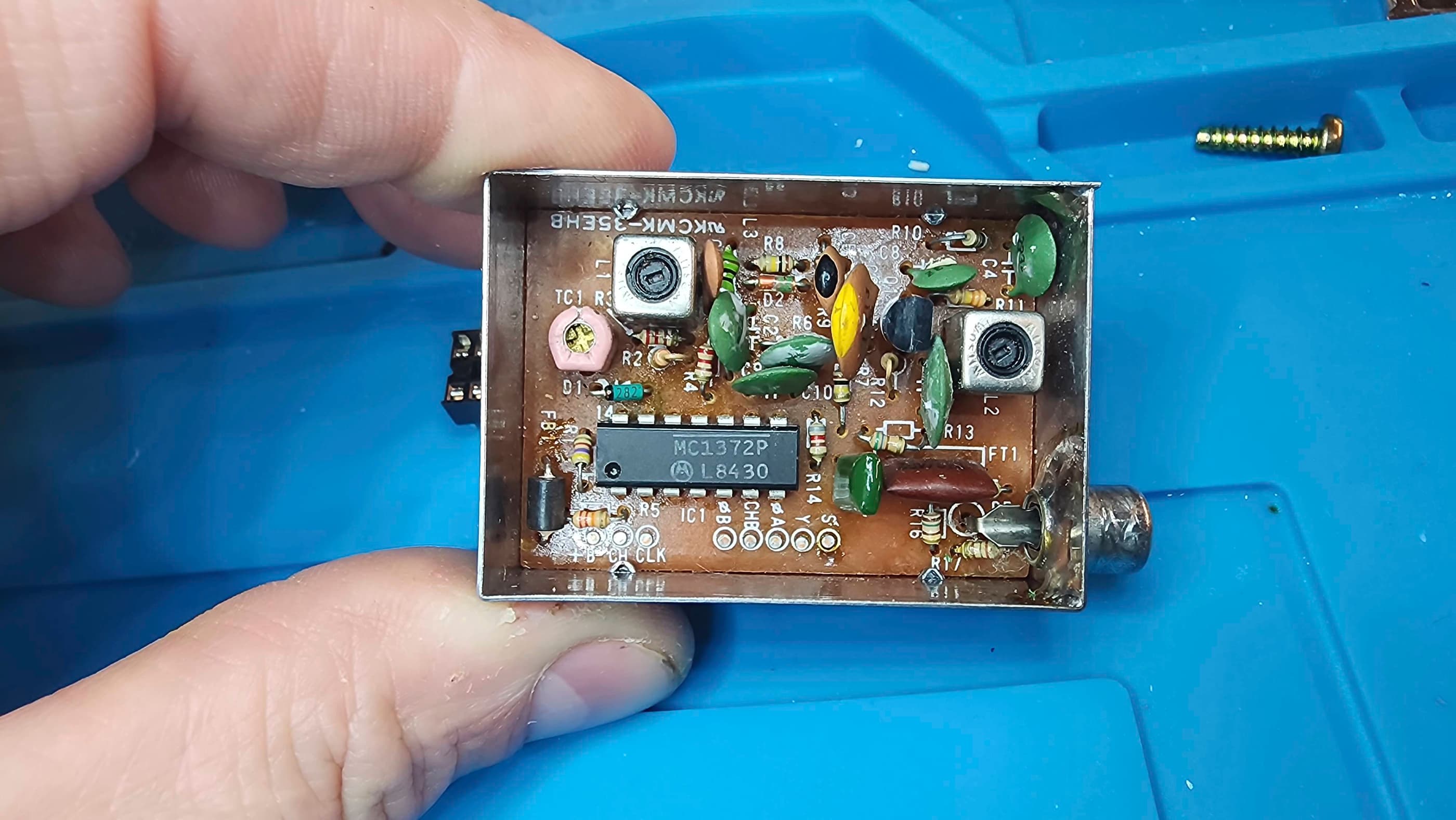
In fact, I’ve never seen an entire series of the same type of ceramic capacitor, exude any form of visible degradation like this. In the modulator, all of the green disc Z tolerance capacitors had a white mould-like substance covering them. They also all had one or more pinhole-sized openings where it looked like the substance had leaked from. This made me think they were a type of tantalum capacitor, but because they weren’t polarized and they were coded in the same format as the neighbouring brown ceramic capacitors, it nullified that idea. Lots of online searching still left me in the ceramic camp, but the white substance threw me for a loop because ceramics don’t leak – or do they? My final speculation was that chemical degradation had resulted in the pinholes and from there, something had caused a reaction to the material inside. I just don’t know…
Nevertheless, I proceeded to try and adjust the modulator’s tuning pots (with a plastic tool) along with the variable capacitor. I could get a decent output occasionally, but it wouldn’t last. In the B & W start-up phase, it was always crystal clear, but as soon as it changed to color, it became largely unreadable.
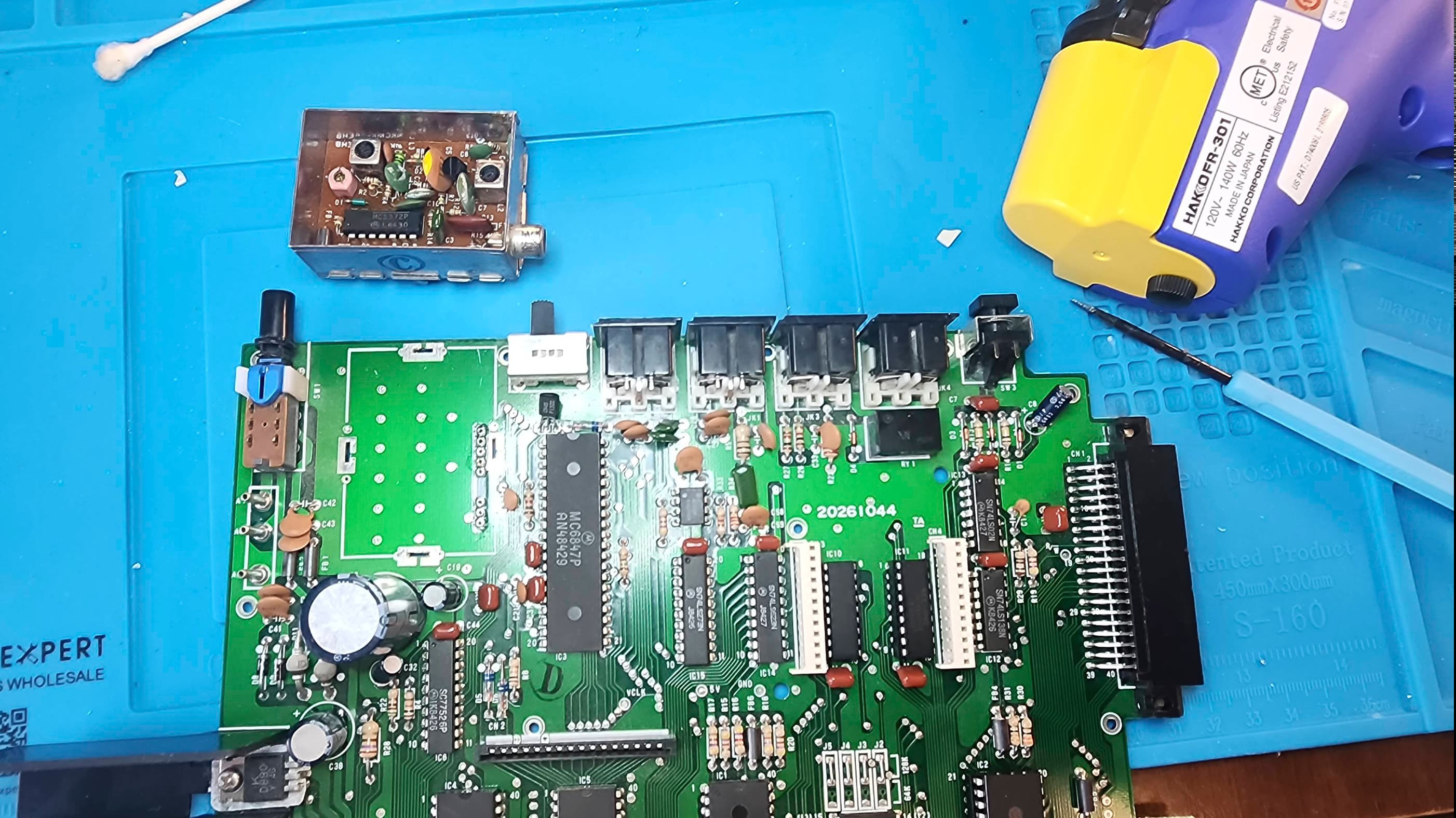
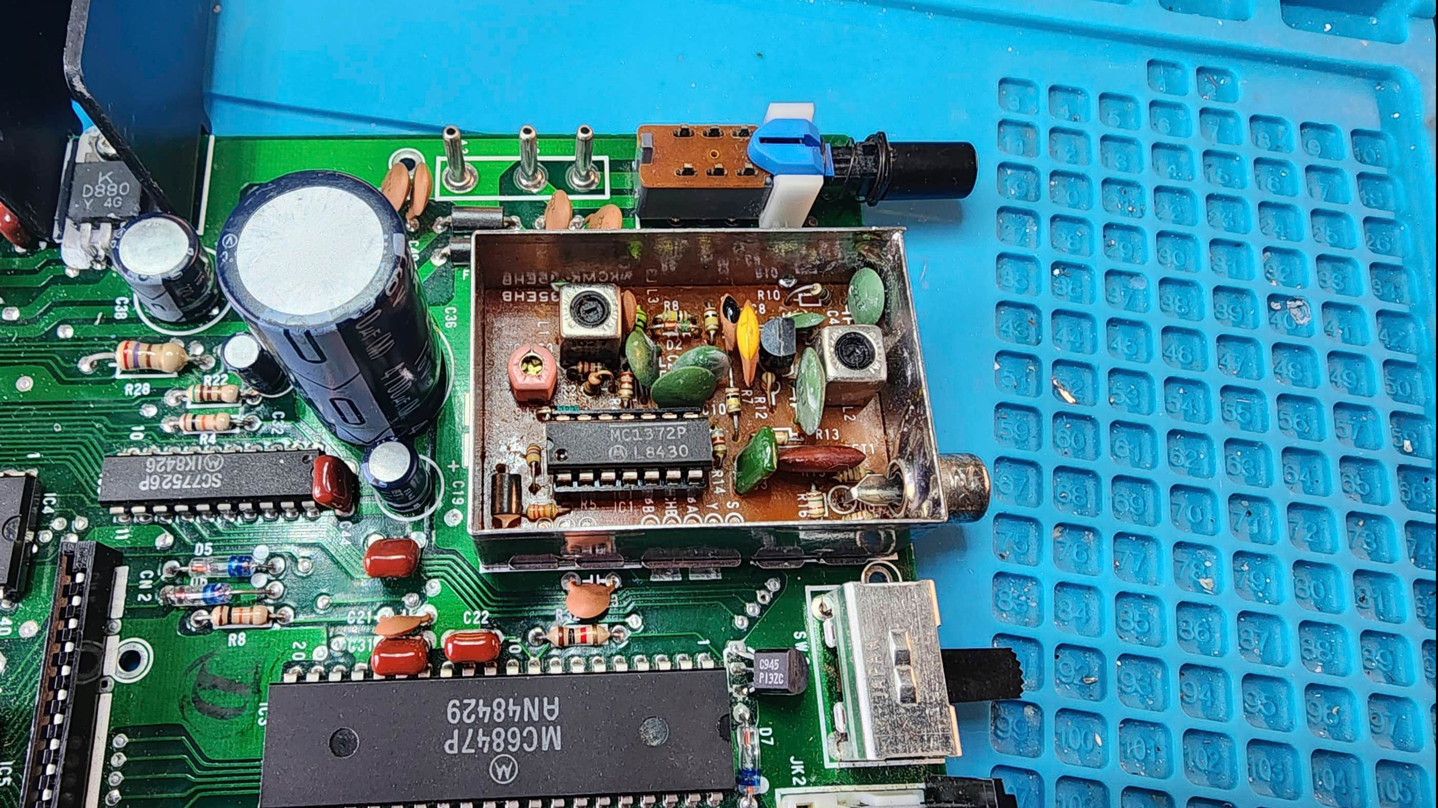
Using the original service manual, I began to troubleshoot with my scope and determined that the incoming signals weren’t abnormal, so the problem was definitely within the modulator. The MC1372P chip inside the modulator, also seemed to be okay. That’s when I decided to remove the modulator to check for loose solder joints.
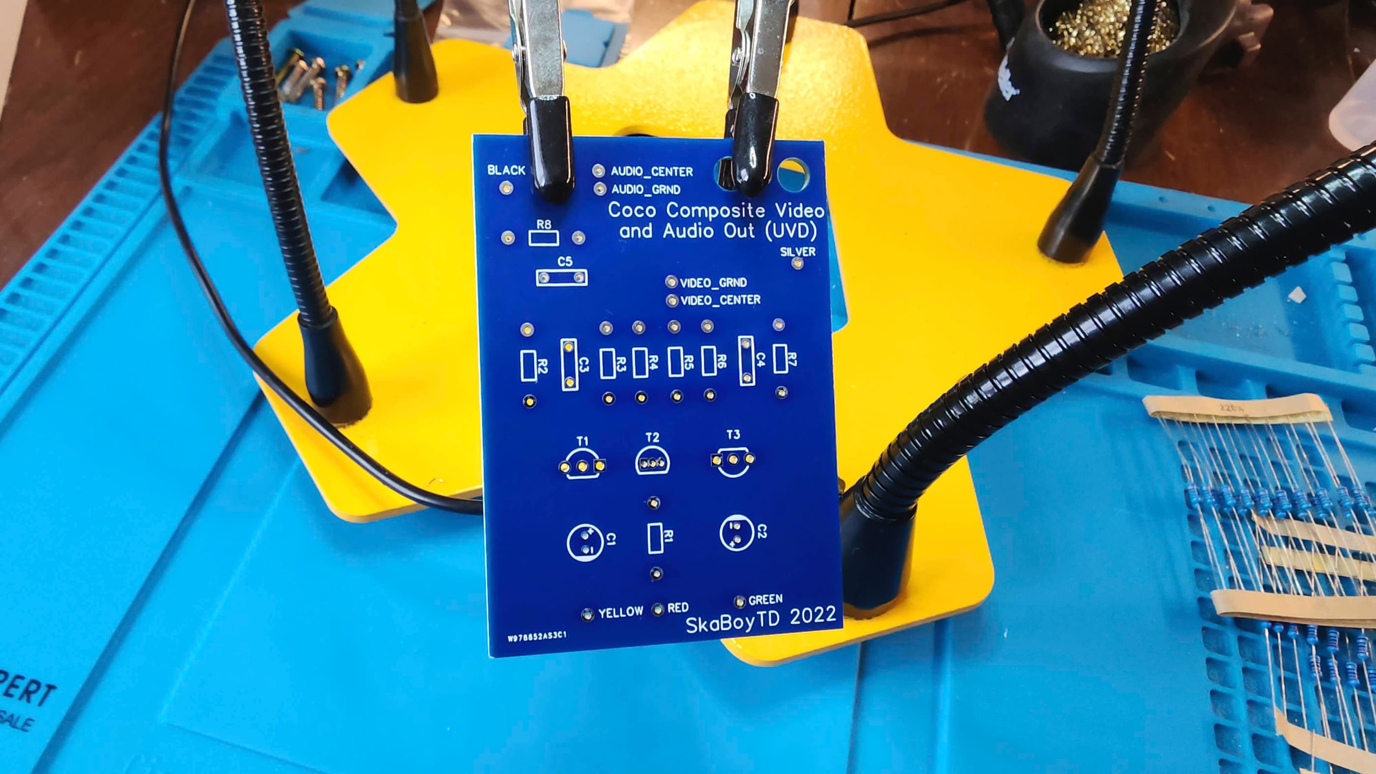
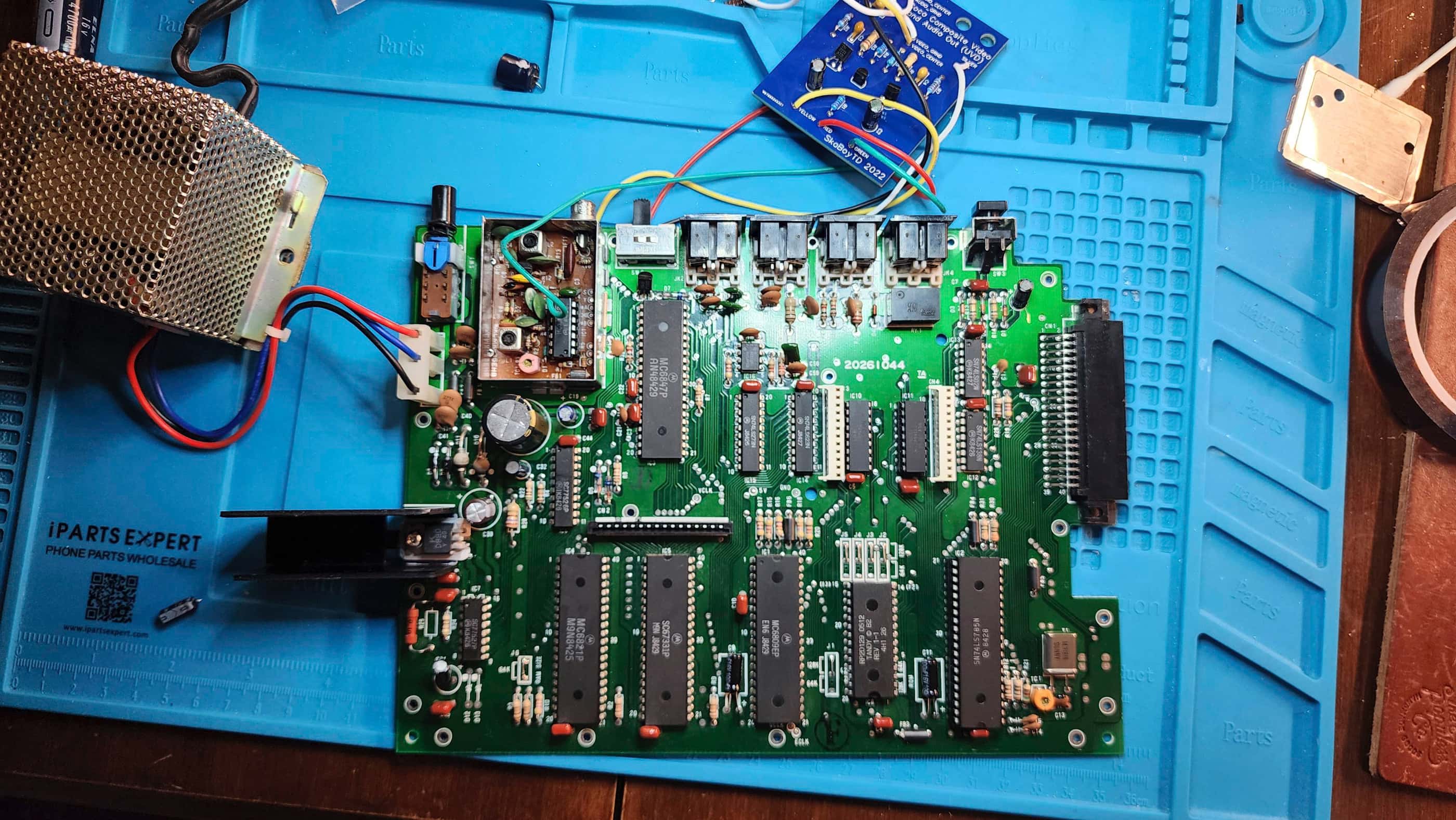
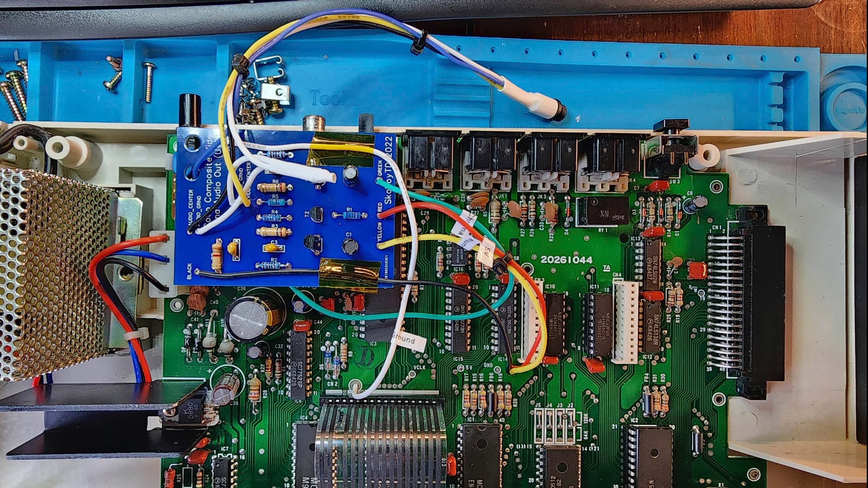
Concurrently, I also began to do an online search for a potential solution that led me to PCBWay where I discovered SkaBoy TD’s 2022 remake of the Mark Data Systems Universal Video Driver (UVD) from the early 80s. This third-party composite upgrade for the TRS-80 Color Computer line intrigued me because it was both period appropriate and because I had all of the components on hand to build it.
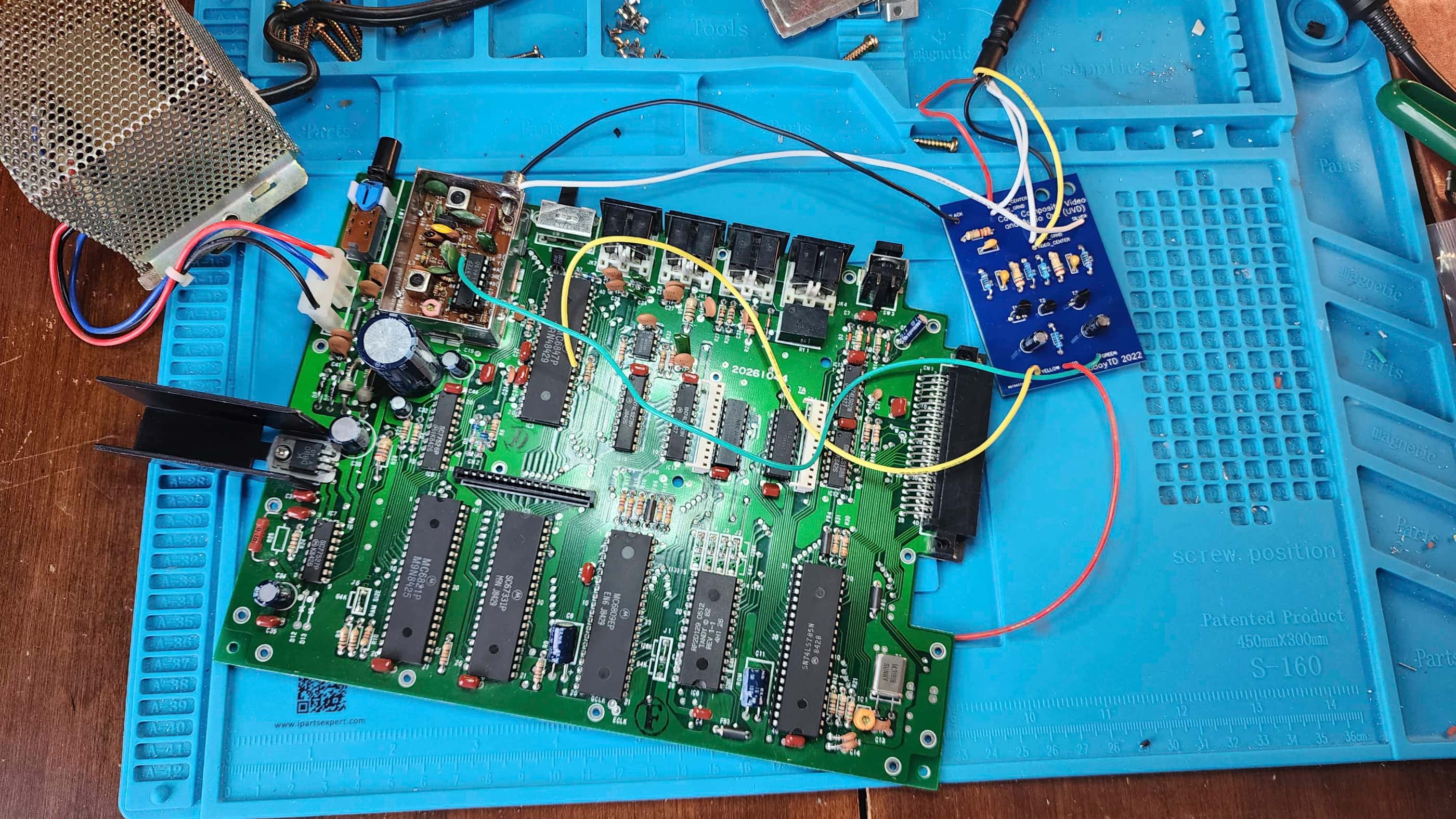
Not finding any loose solder joints and not being able to fix the RF modulator to output a suitable display, sealed my decision to try the UVB composite mod. It didn’t take me long to populate the simple circuit board; though I did note that it could have been made much smaller. Using the original Mark Data Systems instruction manual that I download from SkaBoy TD’s 2022 project page, it was very simple to install.
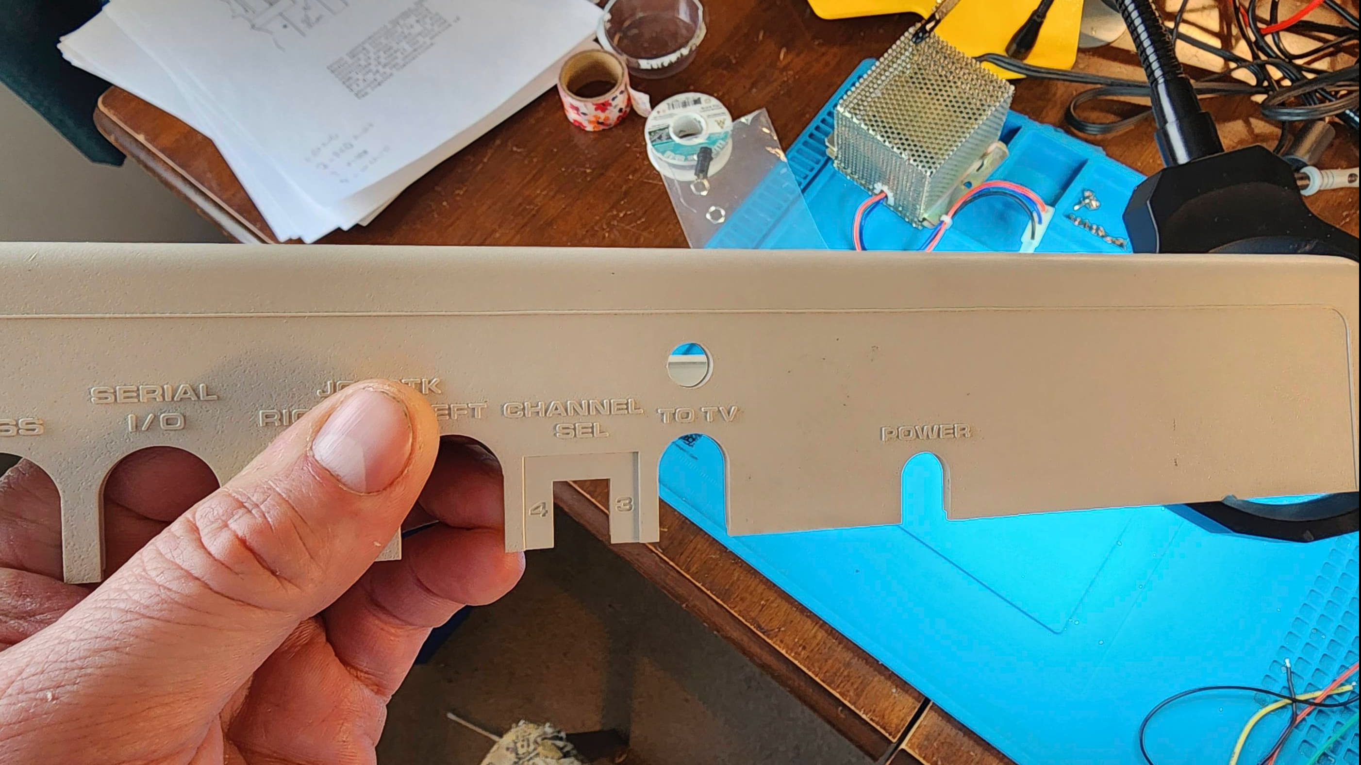
After an initial test to see if it worked, I then set out to establish a more permanent placement. My previous practice with composite mods is to try and minimize altering the original aesthetics of the case and whenever possible, I blend it in to existing holes. However, when I do have to make alterations, I prefer using a single 3.5mm TRRS jack to minimize the damage and maintain the appearance. As the UVB board does not have a natural place for it to fit that is secure enough for a built-in jack, I had to drill a hole and add a TRRS jack.
For placement, I used some alien tape and fastened the UVD to the top of the RF modulator. I then routed the wires to the underside of the board (except for the chroma line which attaches to the MC1372P inside the modulator). I also labelled the wires so someone in the future (probably a grandkid) won’t hate me. For the output jack, I left quite a bit of length so the top case where it would be mounted, could be safely removed without pulling on the PCB.
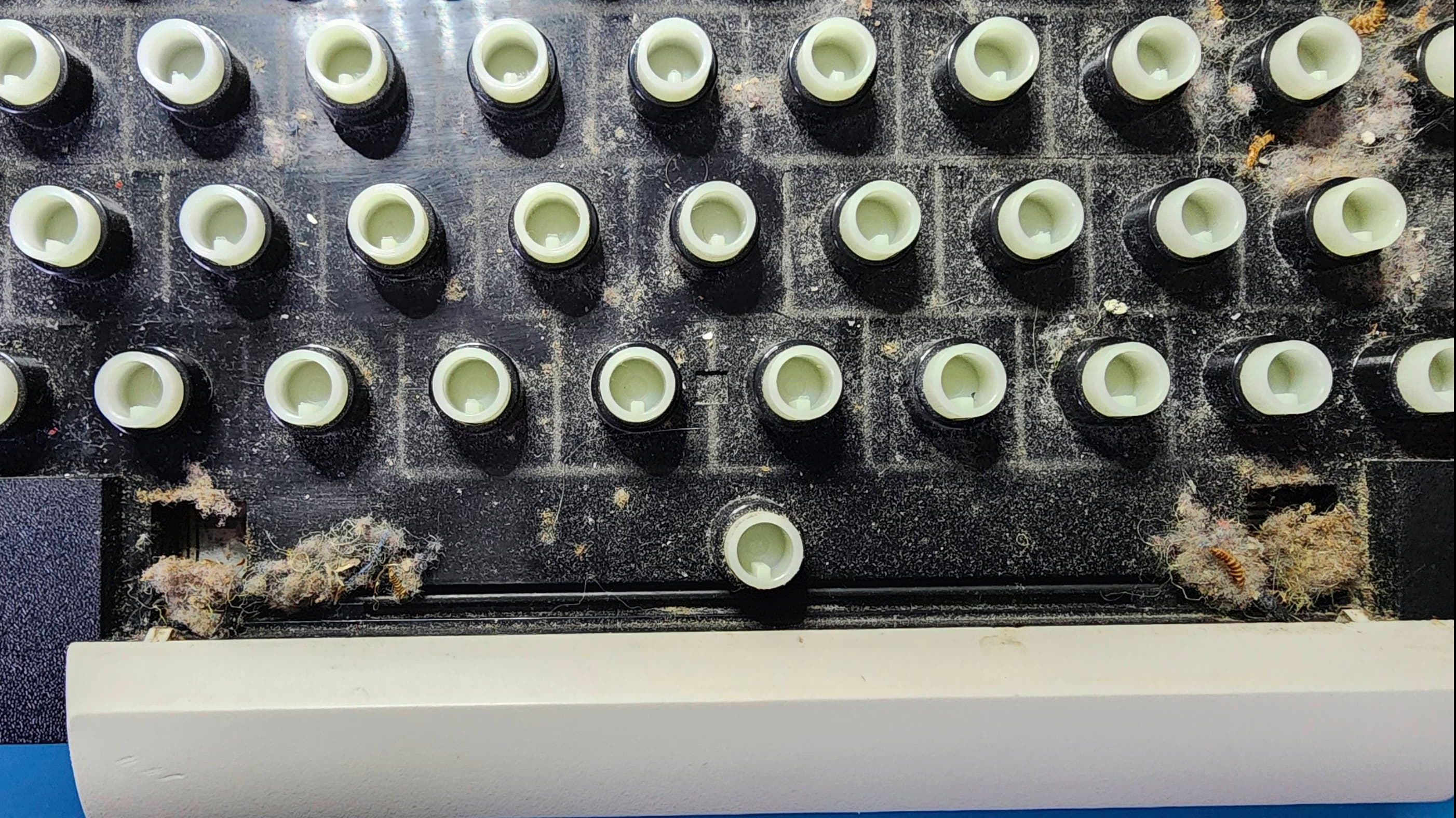
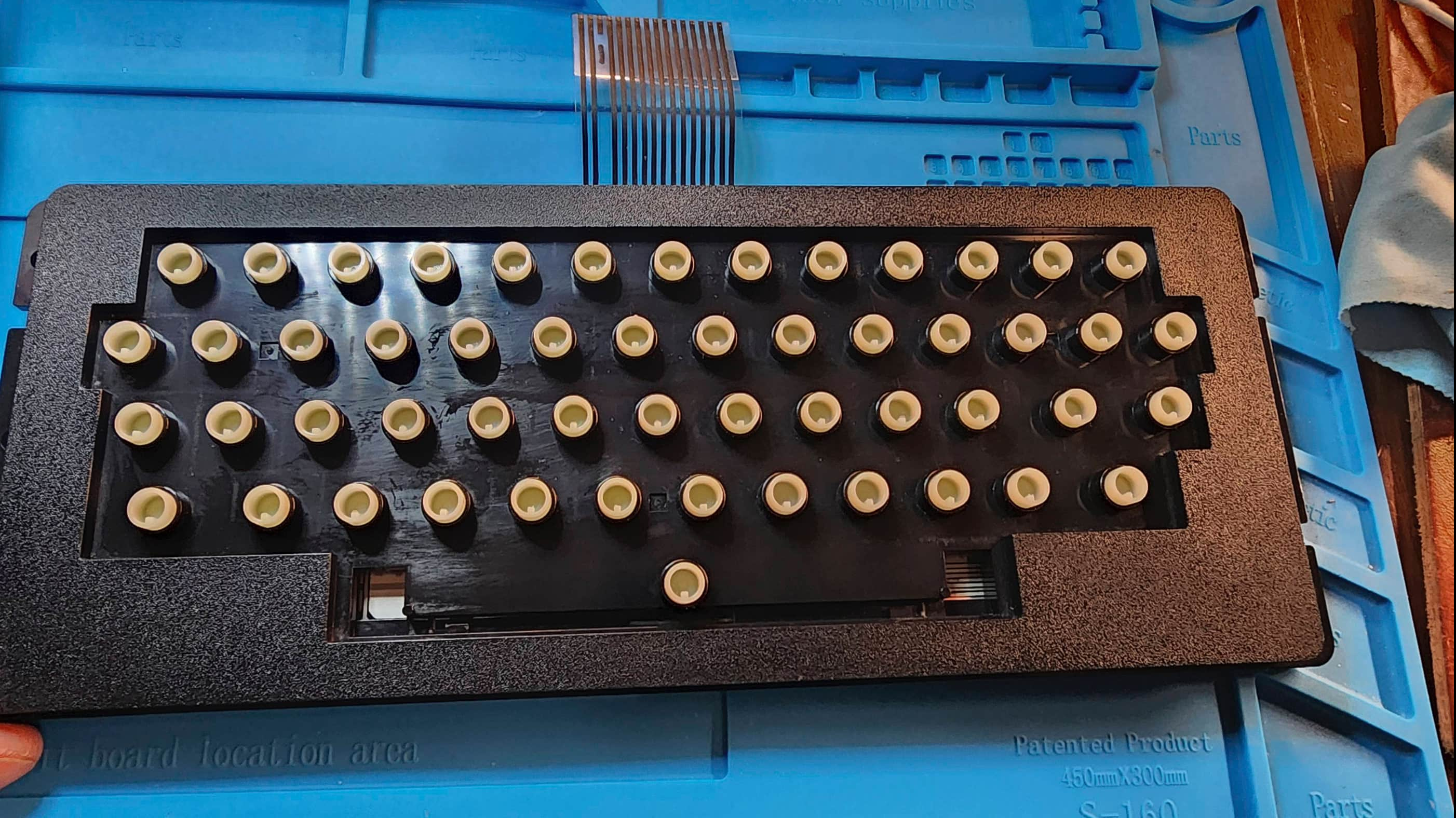
Once tested, I re-capped the board to see if I could enhance video output even further. I also applied non-conductive thermal paste to the regulator on the main heatsink. After testing the unit further and finding everything was working, I then disassembled the keyboard as I observed that it was extremely dirty. It was – including lots of bug exoskeletons to go with the dust bunnies.
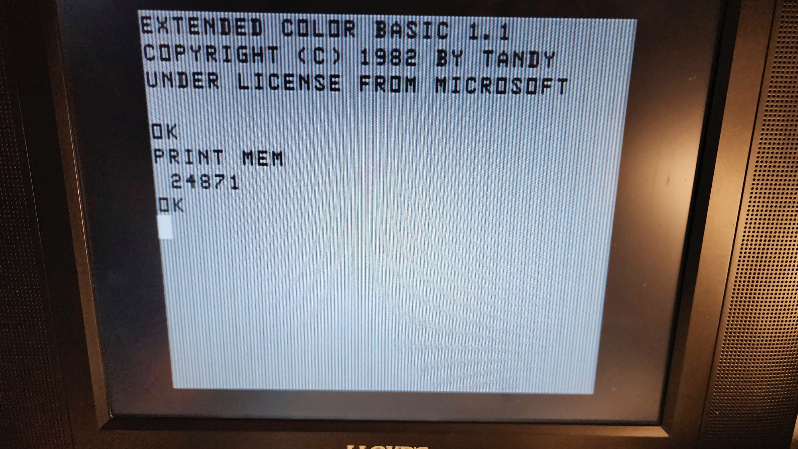
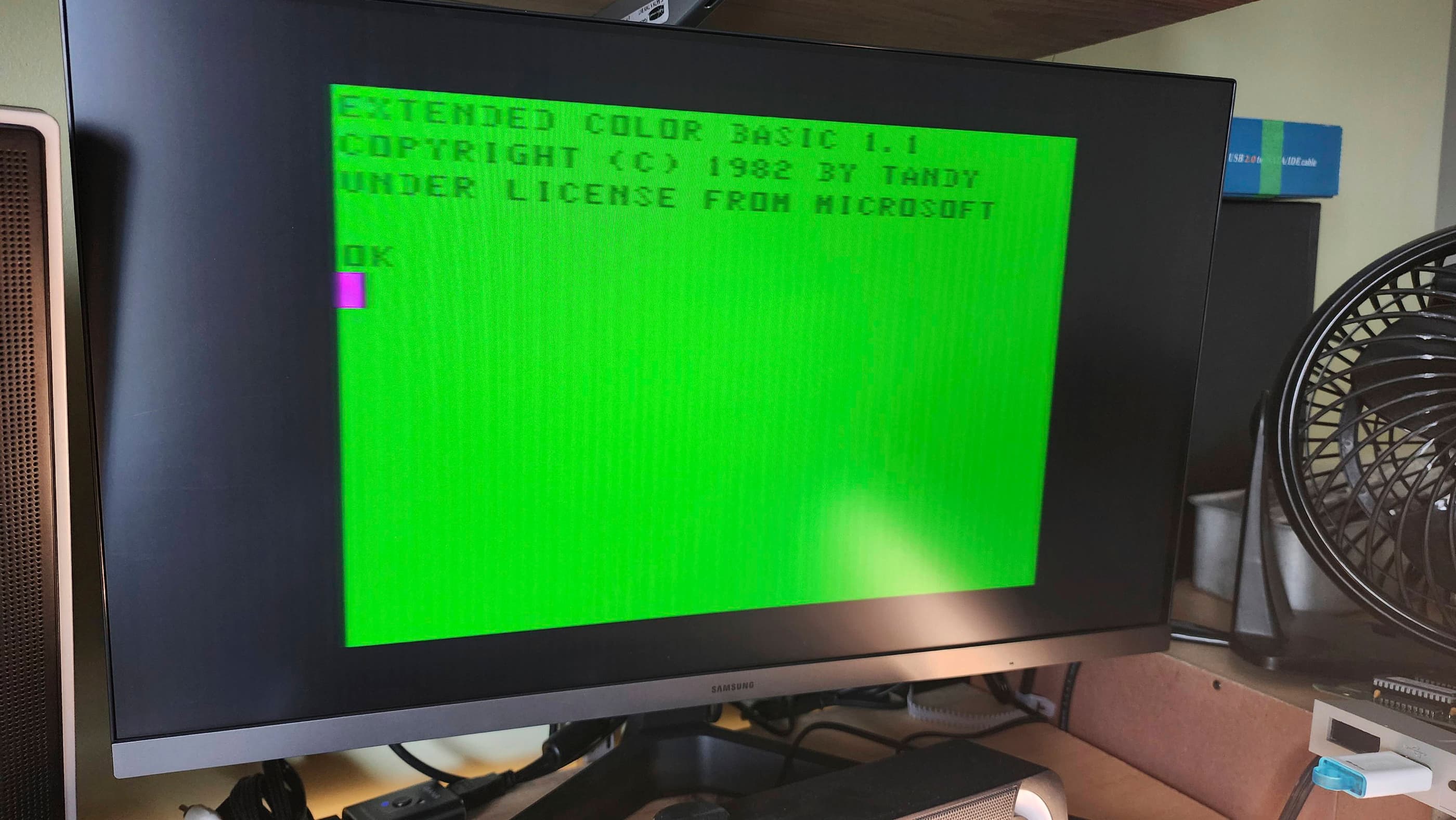
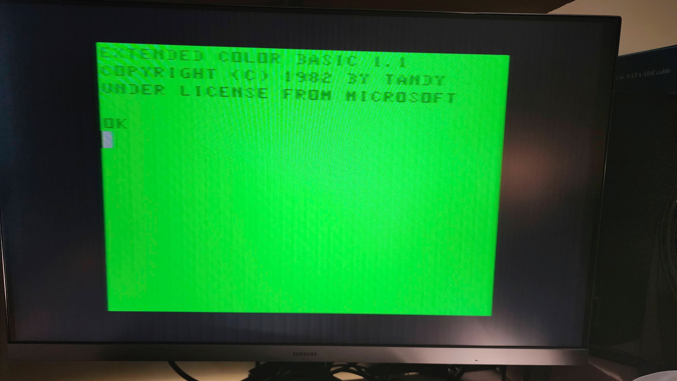
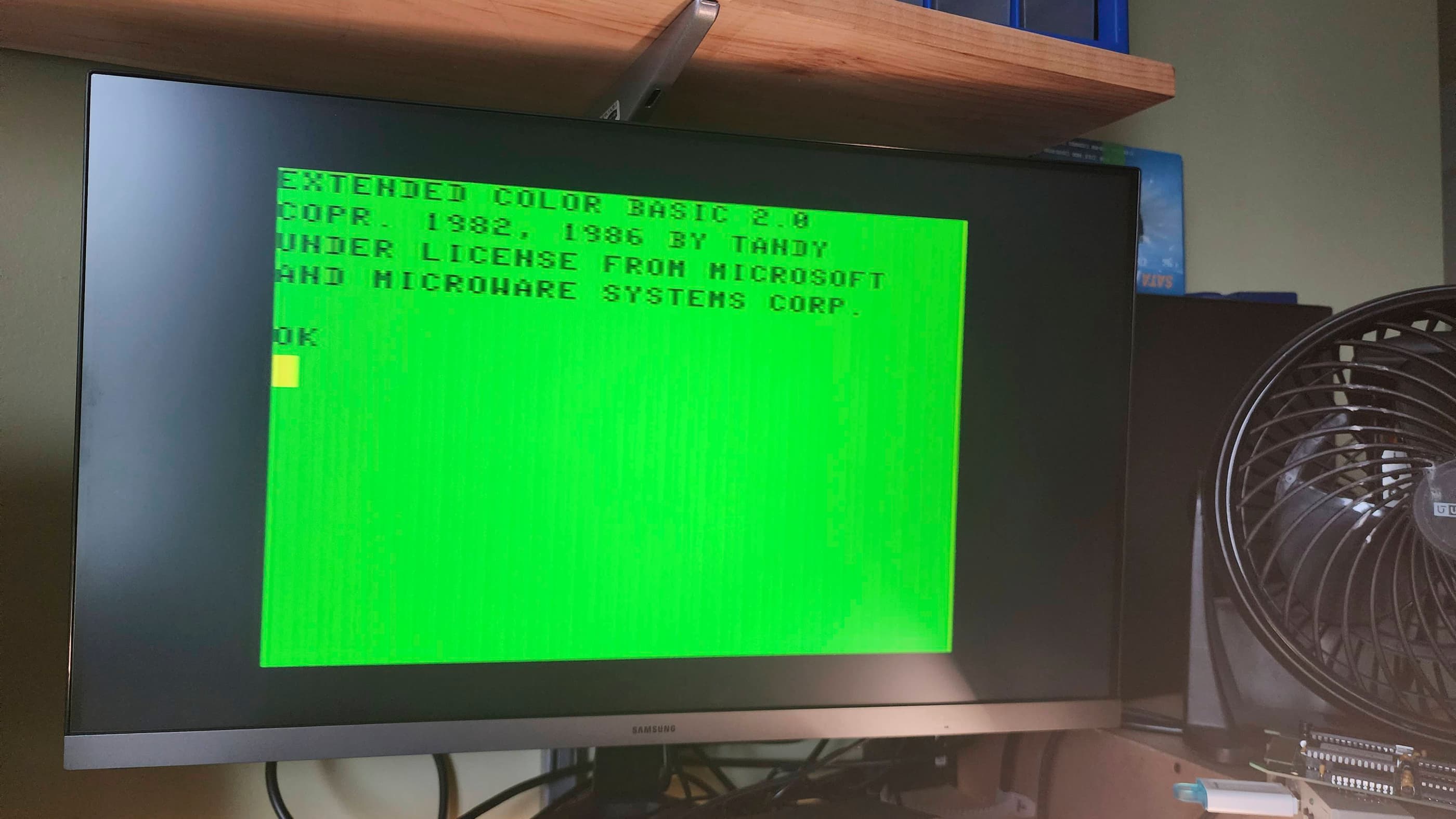
After putting everything back together including the top case, I then tested it with plenty of games. One thing that I still wasn’t able to figure out, was the brightness of some individual characters or symbols when typing in Extended Basic 1.1. These appear faded with quotation marks being the worst offender. Perhaps this is related to a failing ROM….?
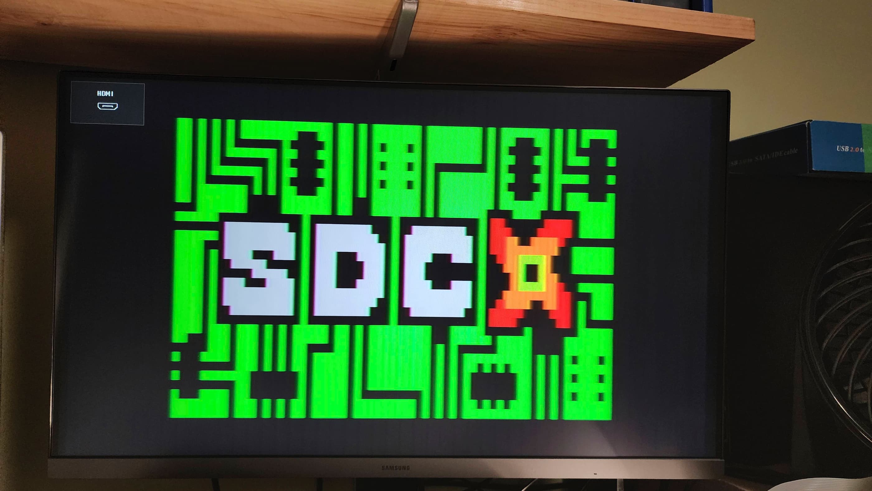
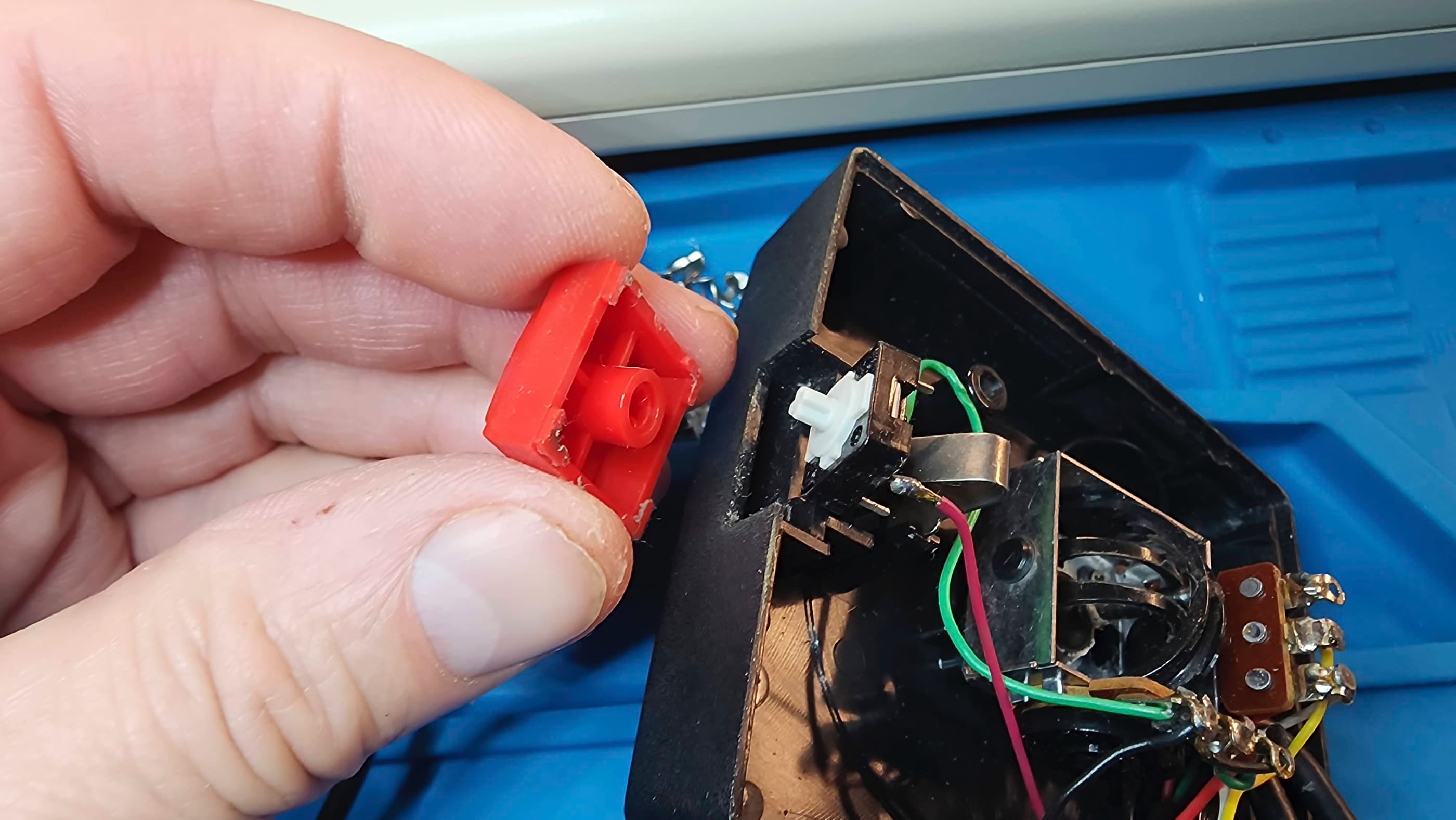
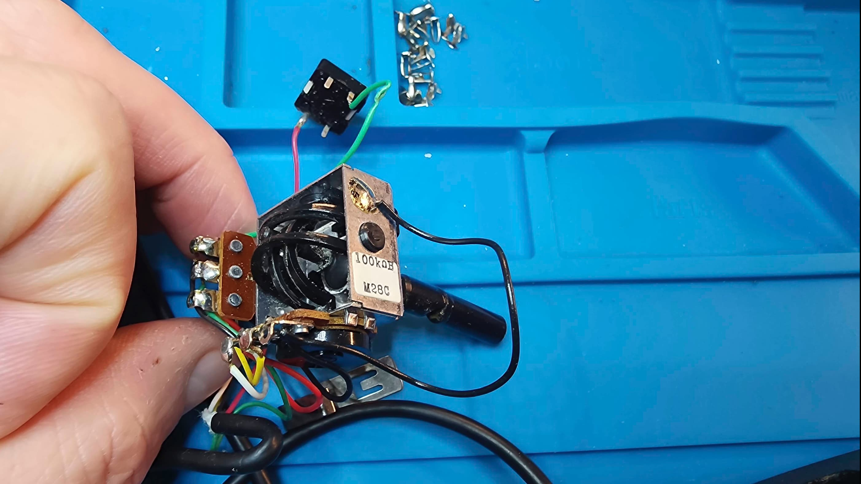
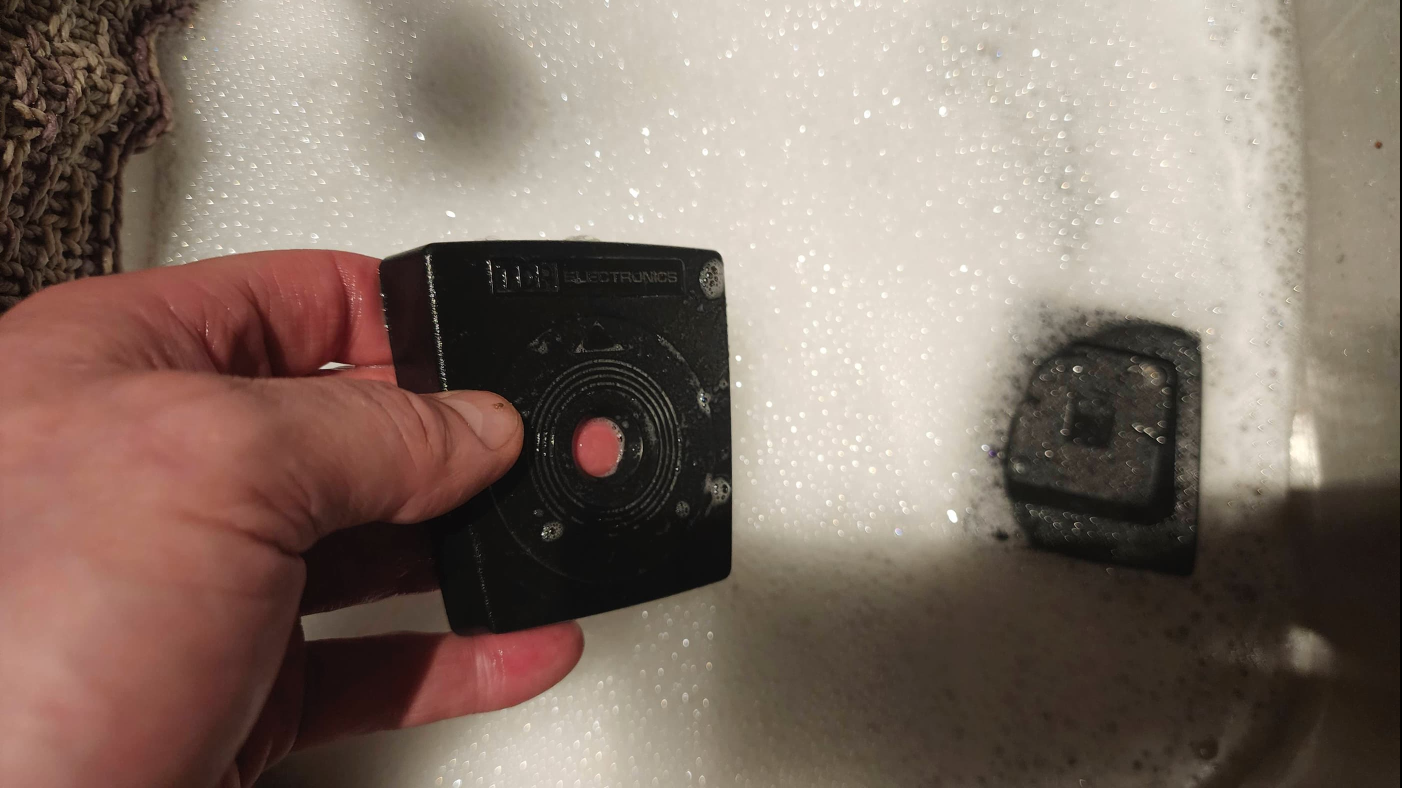
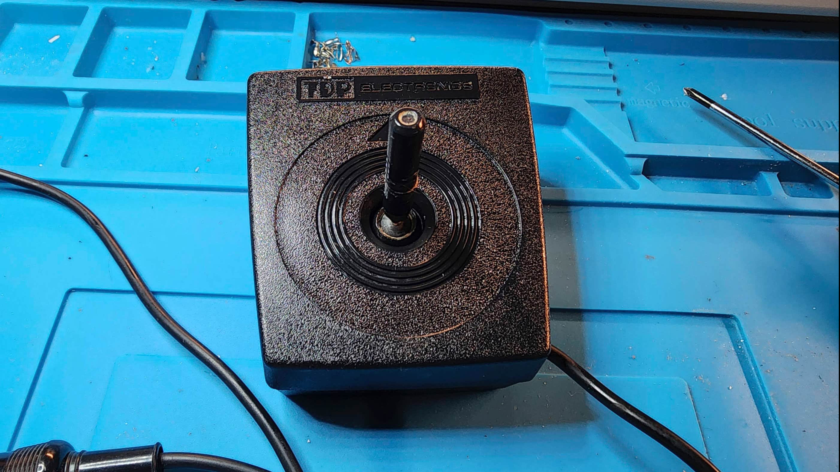
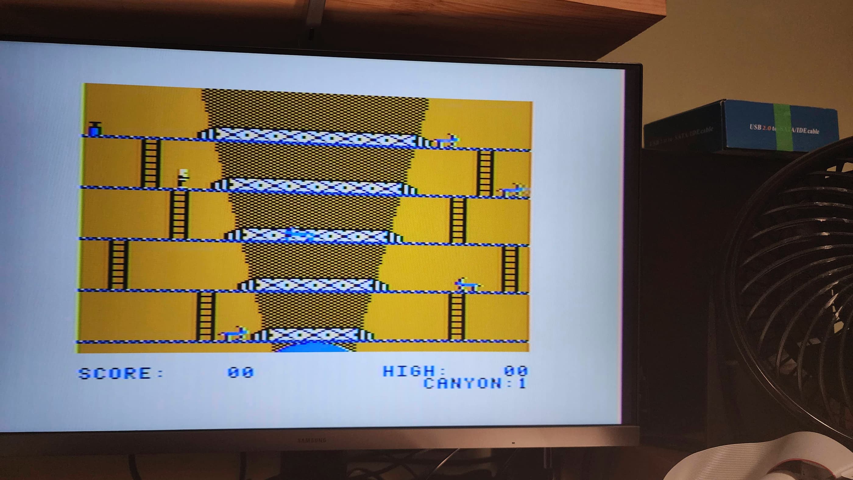
As my CoCo did not come with a joystick and I didn’t have one on hand, I found a used one on EBay. It worked, but it required some cleaning and a repair of the broken control stick. Once that was done, I was able to enjoy a series of games using the SDC Drive Emulator from Retro Rewind.
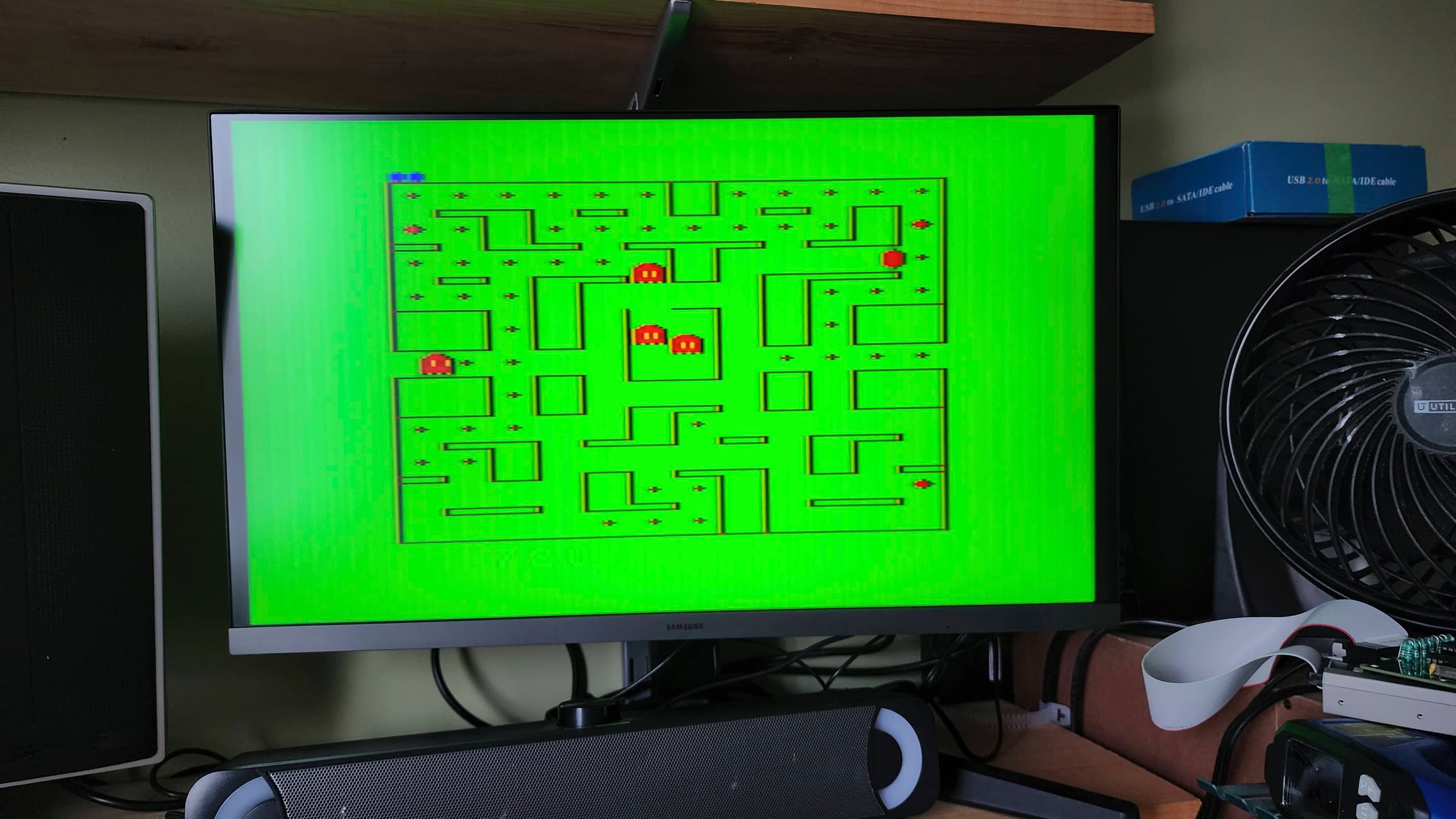
Having never owned a Tandy CoCo 2 – or for that matter, any other Tandy computer before this one – I can see that at the heart of its appeal, lies a quirkiness that distinguishes it from other 8-bit computers of the day. Whether it’s the green background screen with the multi-colour flashing cursor, or the various commands to load and run machine language or basic programs, there’s a certain ‘feel’ to the CoCo. From reading and watching other people who are much smarter and more experienced than I am, it’s obvious that there’s a serious machine underneath the quirky and as I experiment more with the CoCo over time, I’ll come to understand and appreciate this.
Parts & Products Used: 99% isopropyl alcohol; Chemical Guys Natural Shine; Deoxit D5; mainboard electrolytic capacitors (radial) – 16v 47μF Bi-Polar (1); 16v 100μF (3); 16v 220μF (1); 16v 4700μF (1); 25v 10μF (1); 50v 1μF (1); SkaBoy TD 2022 UVD composite mod (1); UVD components: electrolytic capacitors: 50v 1μF (1); transistors: 2N222 (2); 2N3904 (1); ceramic capacitors: 30pF (2); 10 nF (2) – original calls for 1 – 22nF but I did not have one so I used 2 10nF in parallel to get as close a value as possible; resistors: 47R (1); 1K (1); 2.2K (1); 3.3K (1); 200K (1); thermal paste; Permatex Plastic Welder (cream colour); 24 gauge wire; Retro Rewind Coco SDC

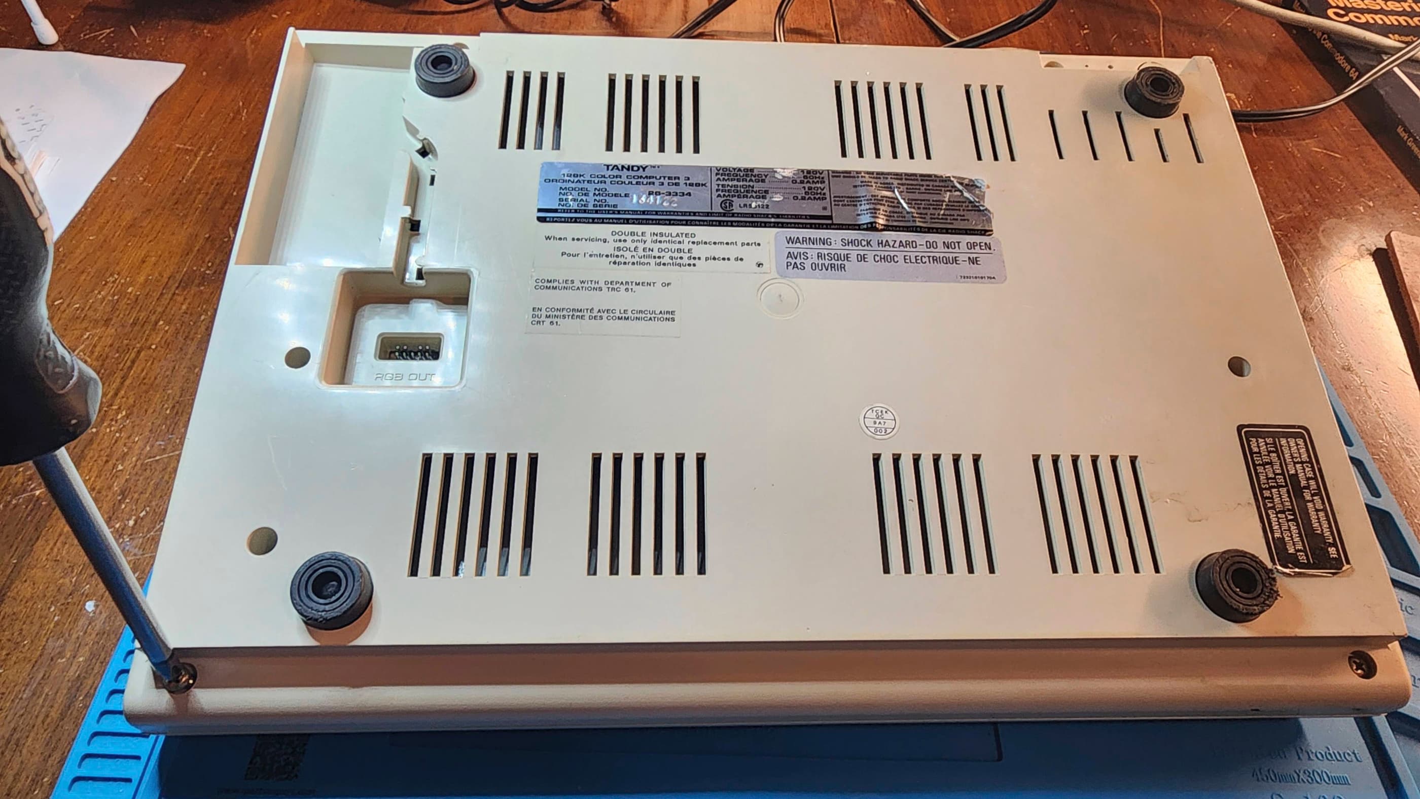
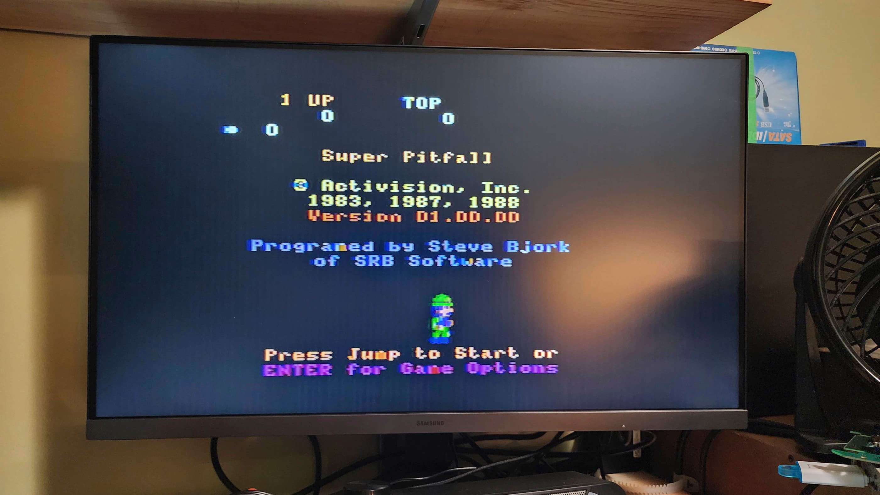
Tandy TRS-80 Color Computer 3 (512MB)
Years (1986-1991)
Interesting Fact: Introduced on July 30th, 1986, the CoCo 3 was the final offering in Tandy’s 8-bit TRS-80 Color Computer line. It came with 128K but was upgradable to 512K – and even 2MB through third-party peripherals. (source) The SAM chip that was used in previous models was replaced with the GIME (Graphics Interrupt Memory Enhancer) (source) that allowed for both RGB and composite video output, new video output resolutions, and 16 simultaneous colours from a palette of 64. (source) The RGB output however, could only be used on an RGBA monitor, that Tandy sold separately as the CM-8 monitor. (source) In addition to the new GIME chip, Tandy also replaced the 1Mhz Motorola 6809E chip with a 2Mhz Motorola 68B09E chip (source).
Condition When Acquired: Non-Functional
Current Condition: Fully Functional
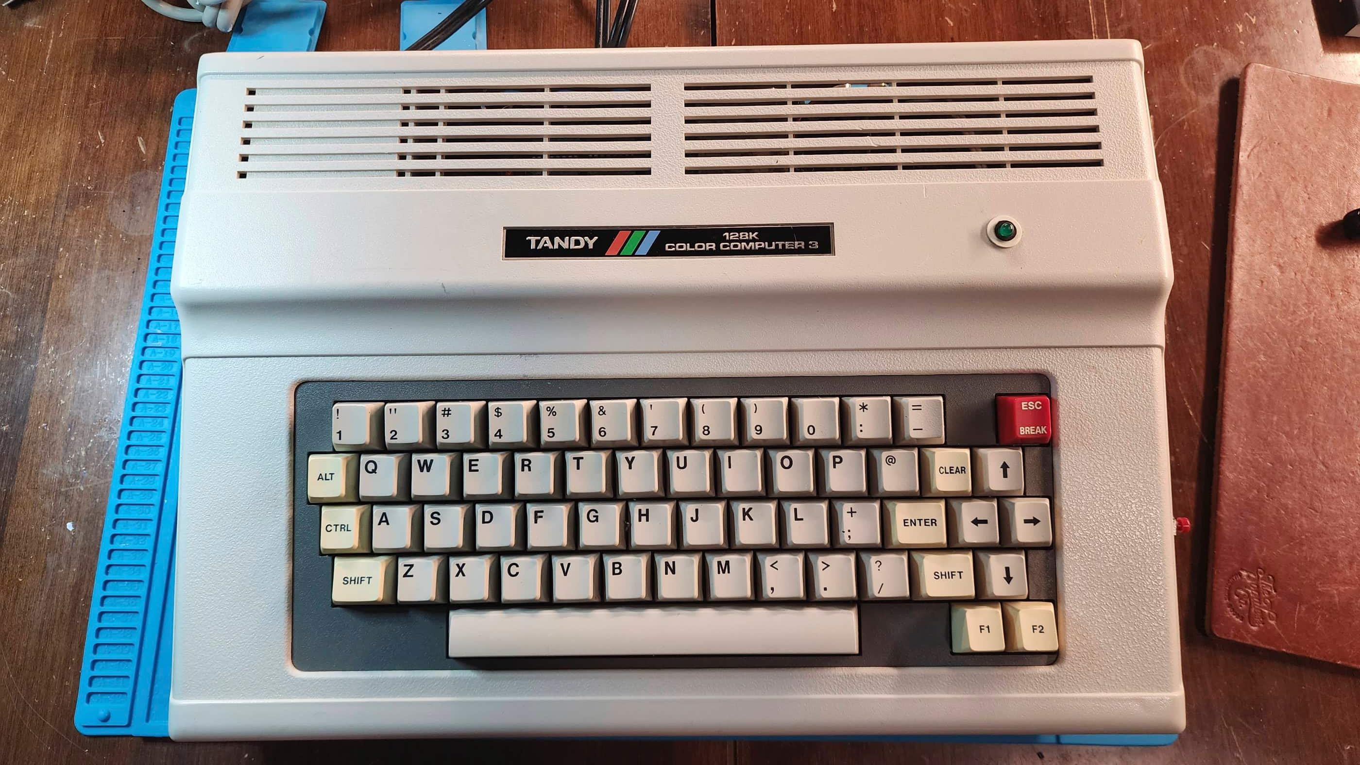

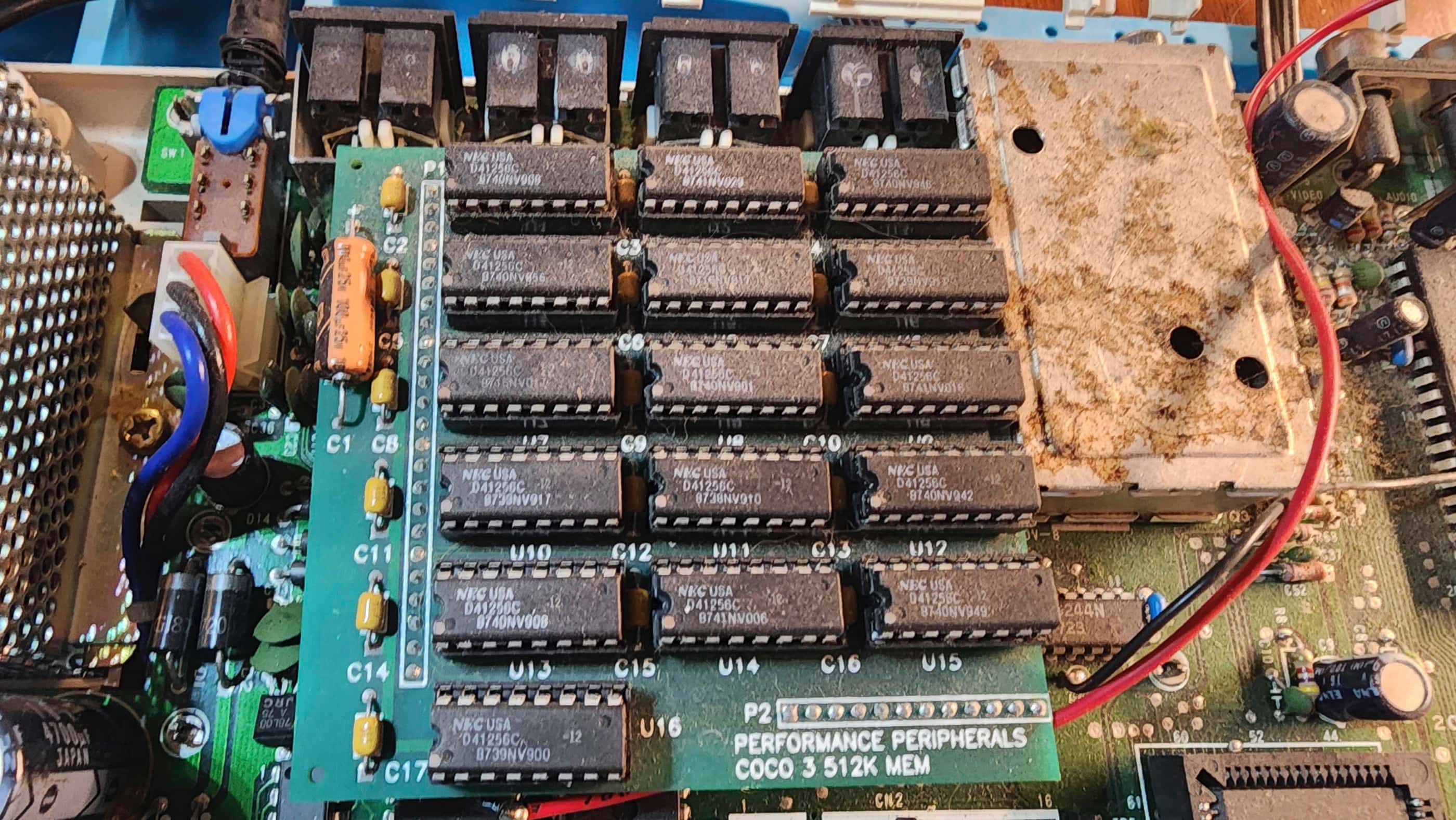
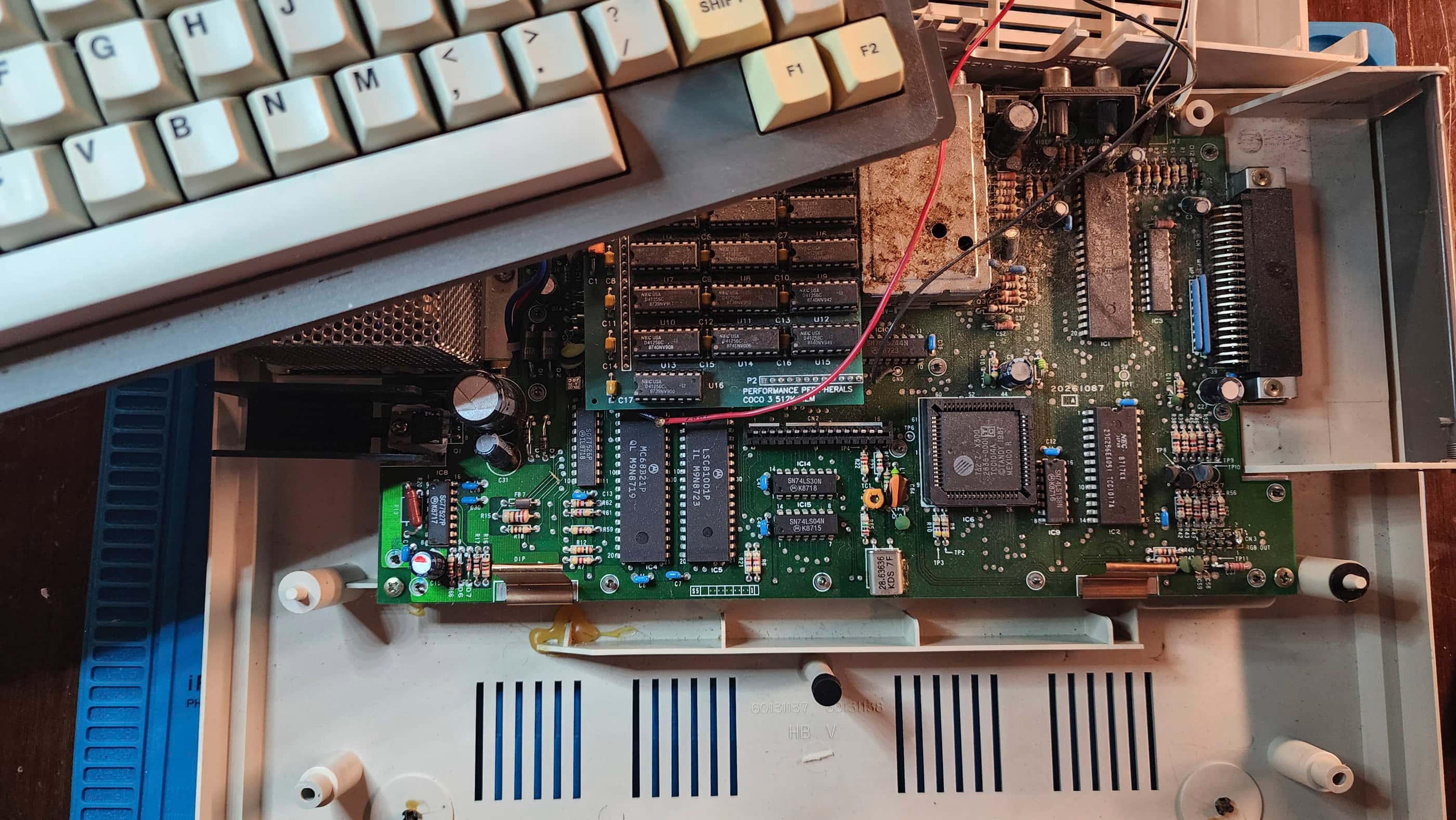


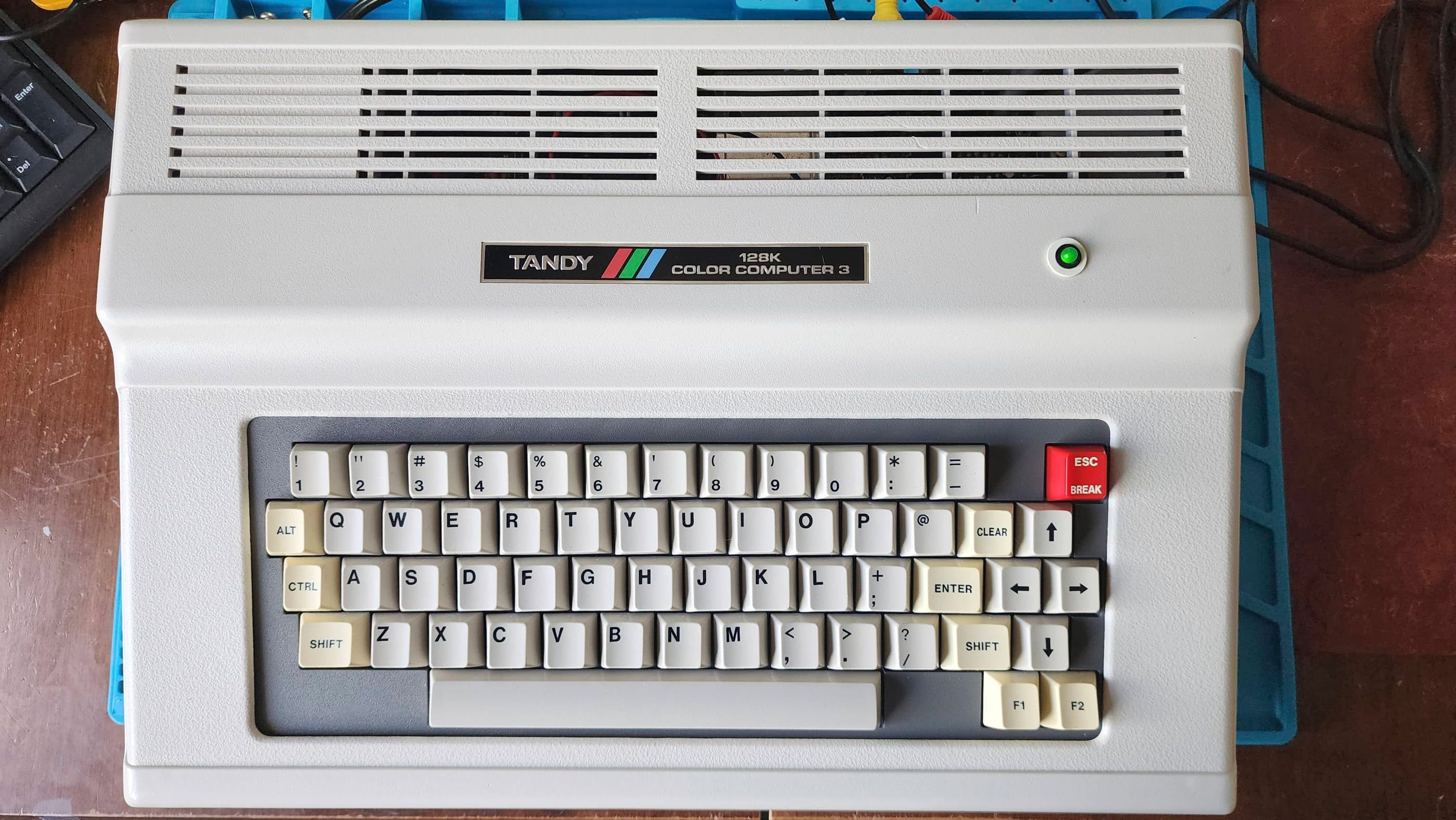


Project Details: I feel like CoCo 3’s are a bit harder to come by, at least in Canada. So, when I came across this CoCo 3 at a reasonable price, I acted on a hunch and bought it. The previous owner noted that the ‘power light’ came on, but had done no further testing to confirm it actually worked.
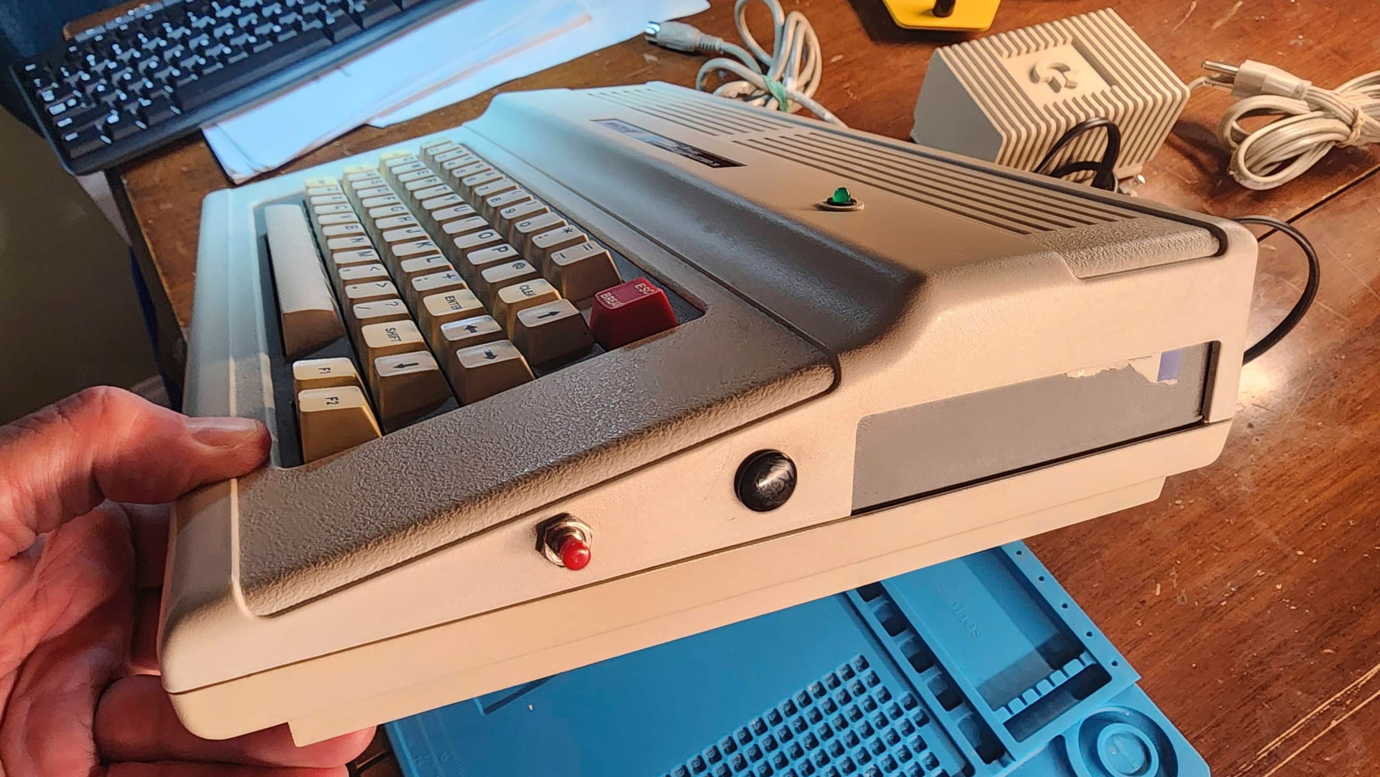
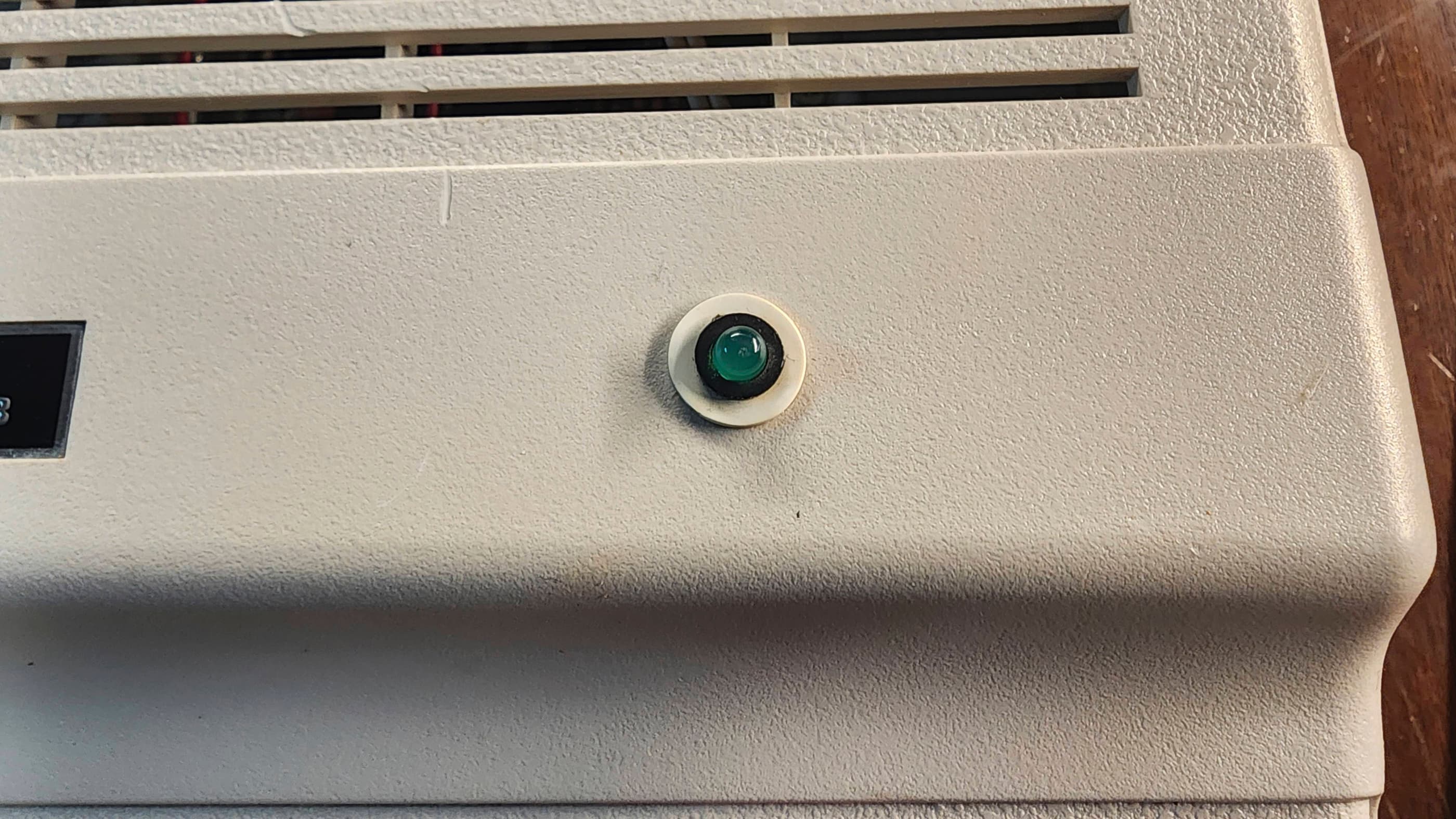
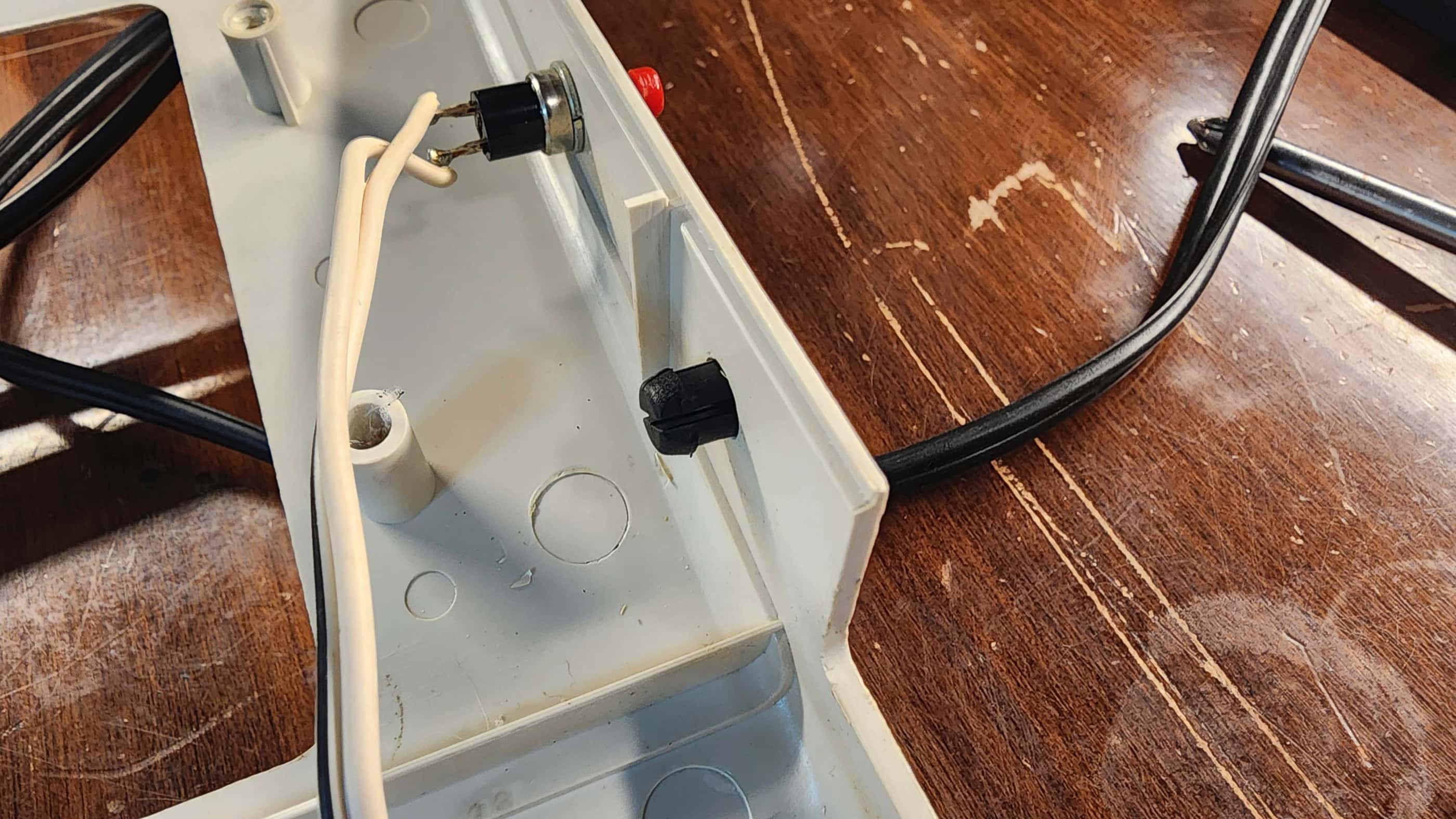
That it had a power light, told me that someone had been inside of it at some point to add one, because CoCo 3’s did not come with one from the factory. After receiving it and confirming that it was definitely a previous mod, I also noted that someone had installed a second reset button on the side of the computer. This was really weird to me as it was simply piggybacked from the stock reset switch on the back of the machine. 🤔 It would only dawn on me later why this might have been done.
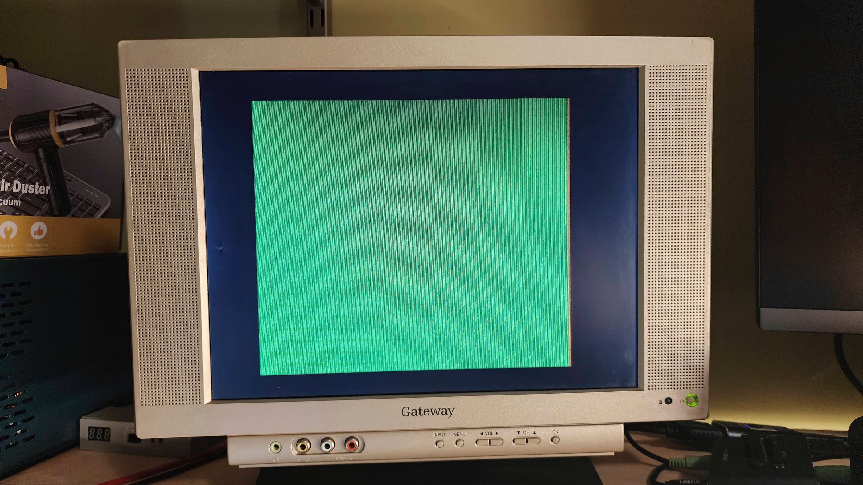
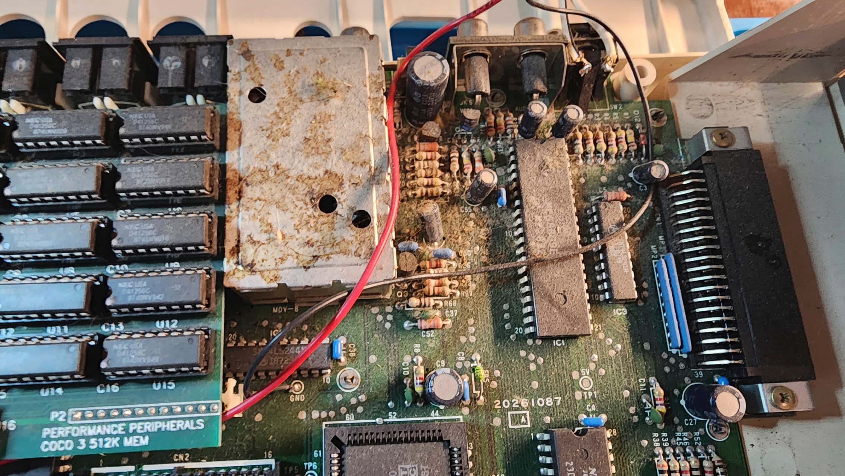
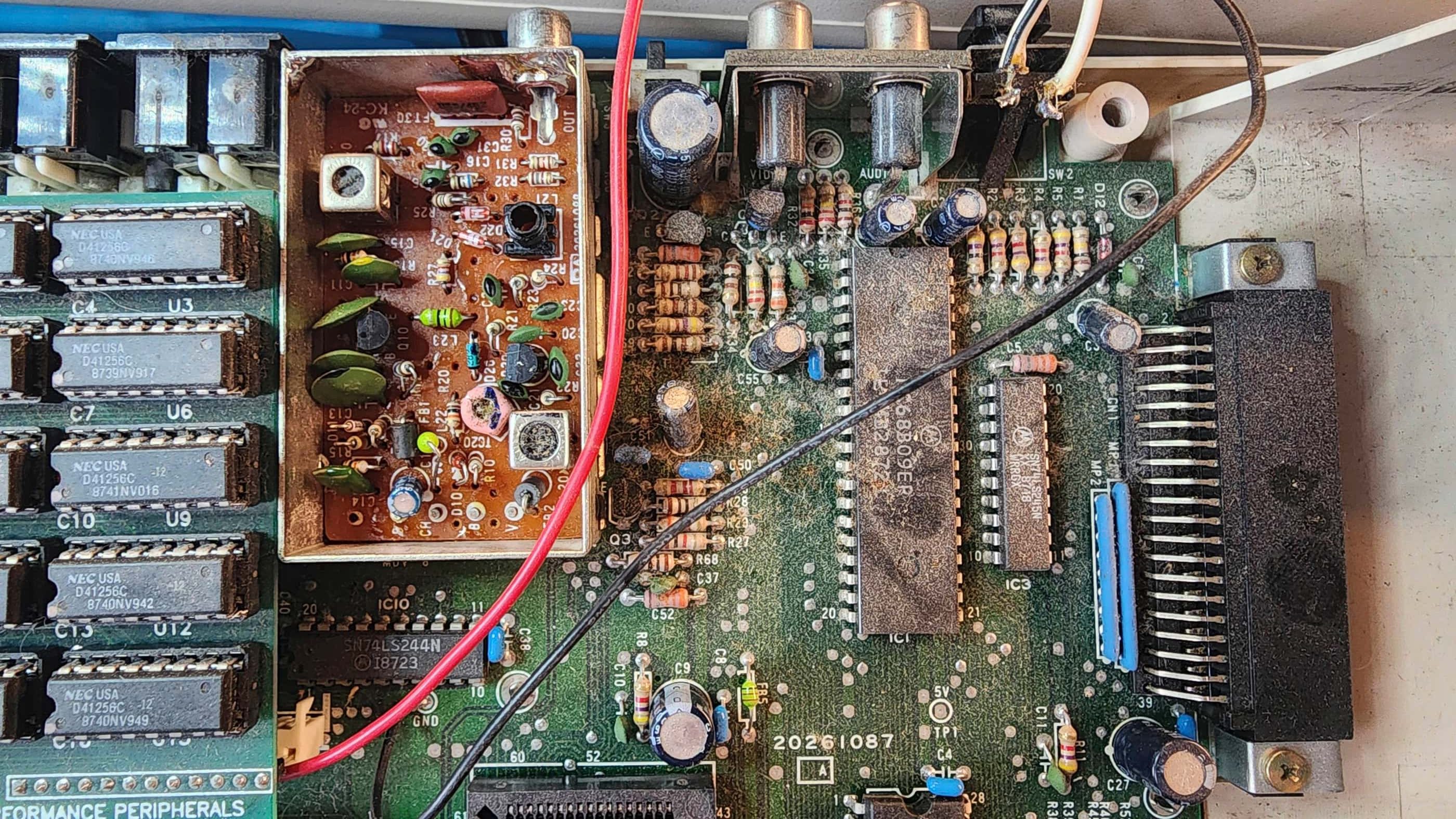
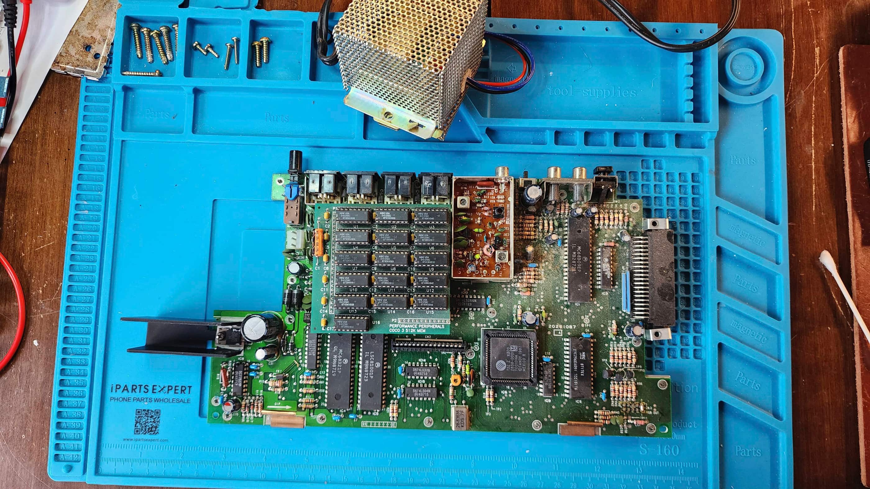
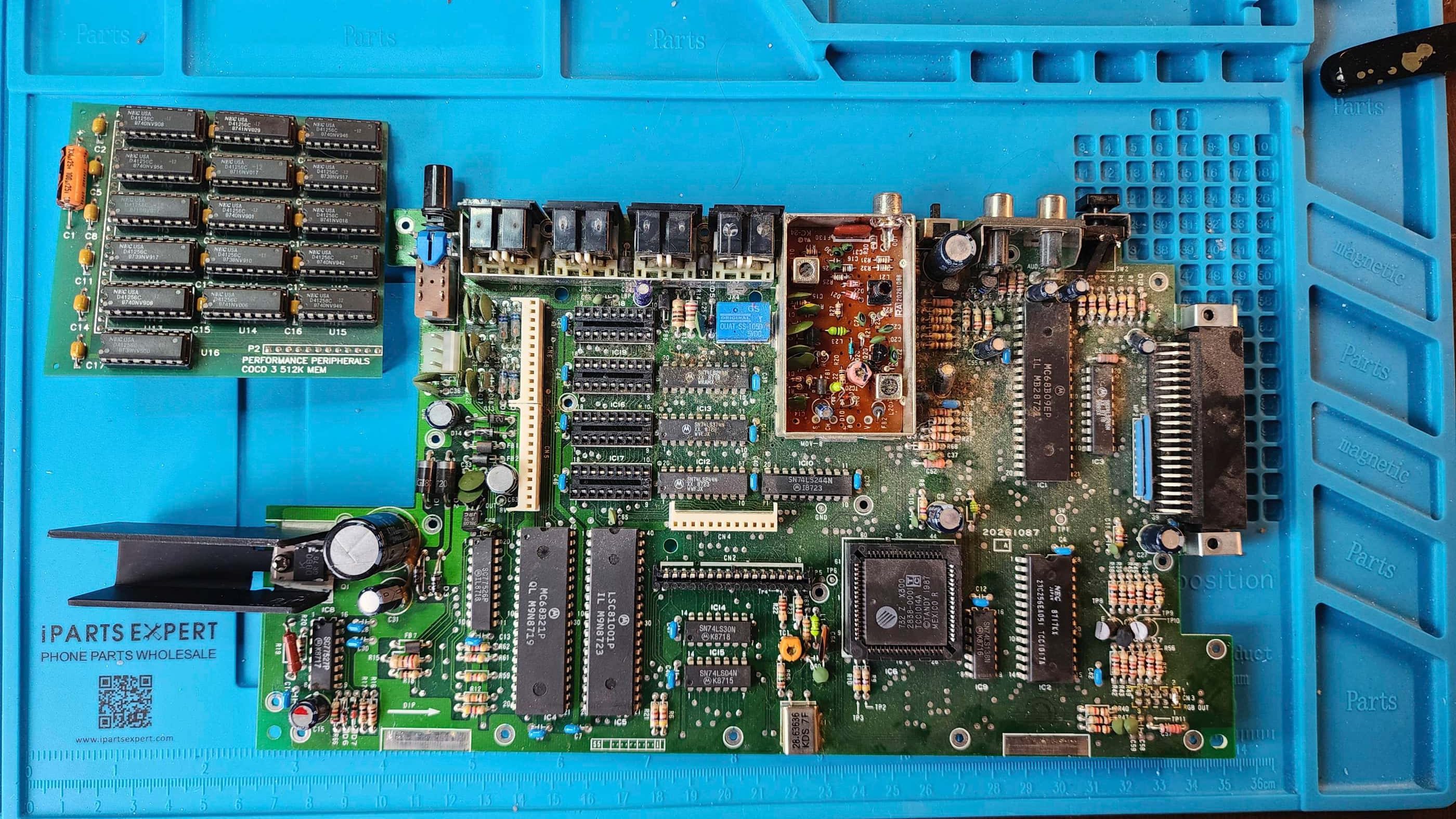
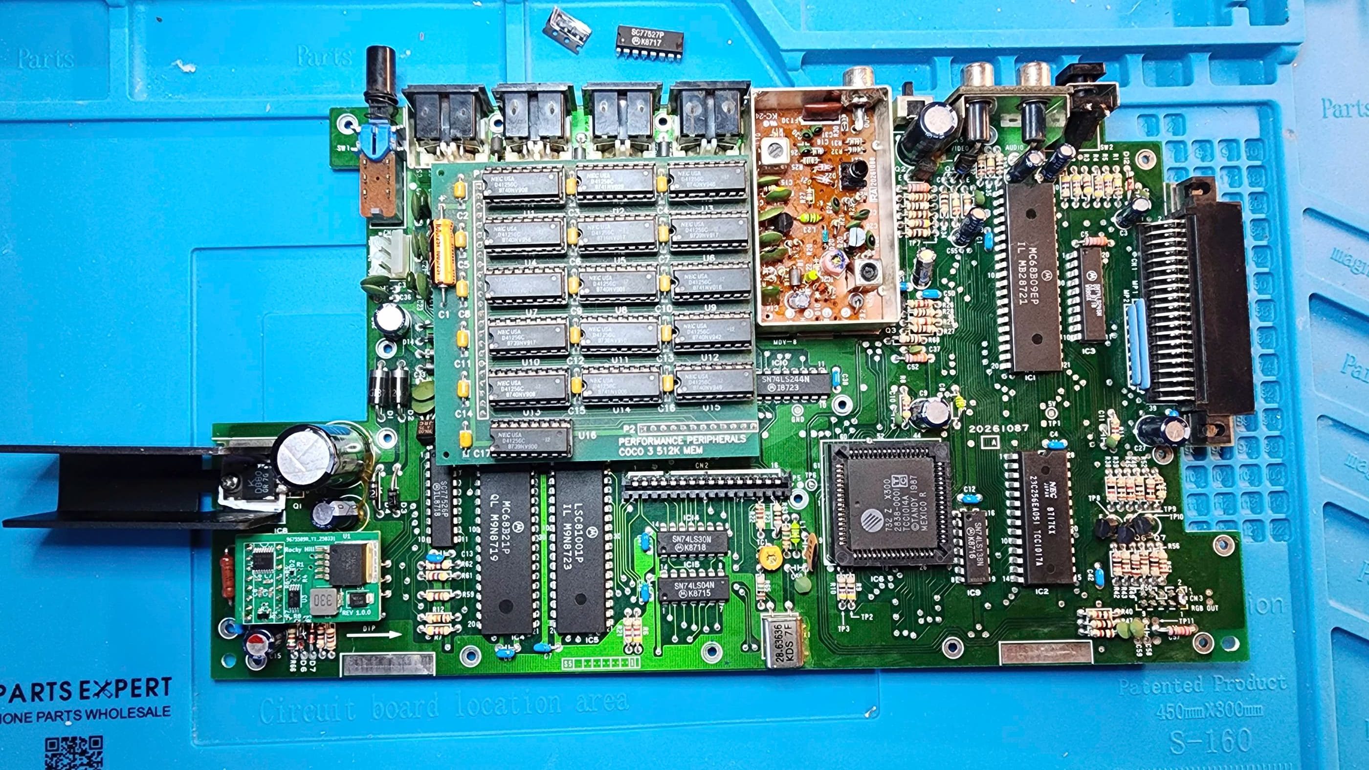
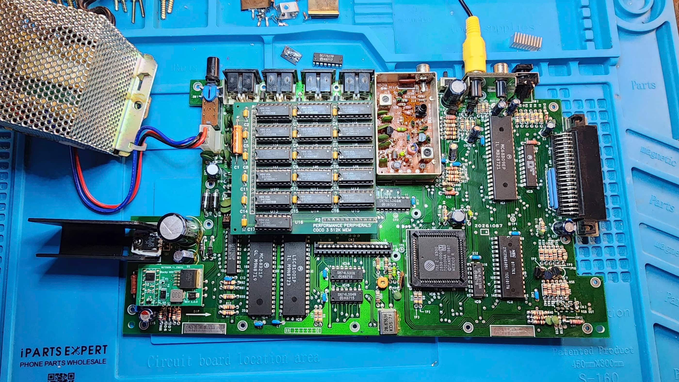
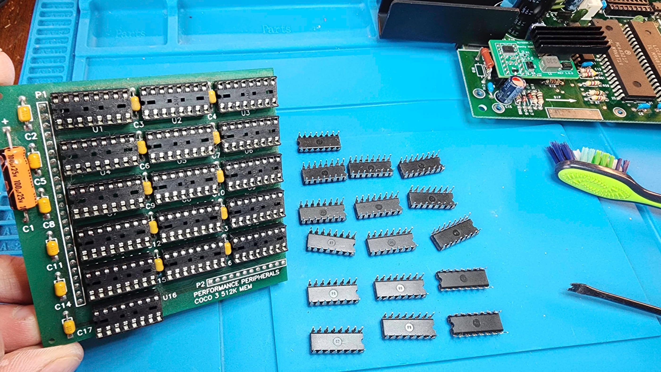
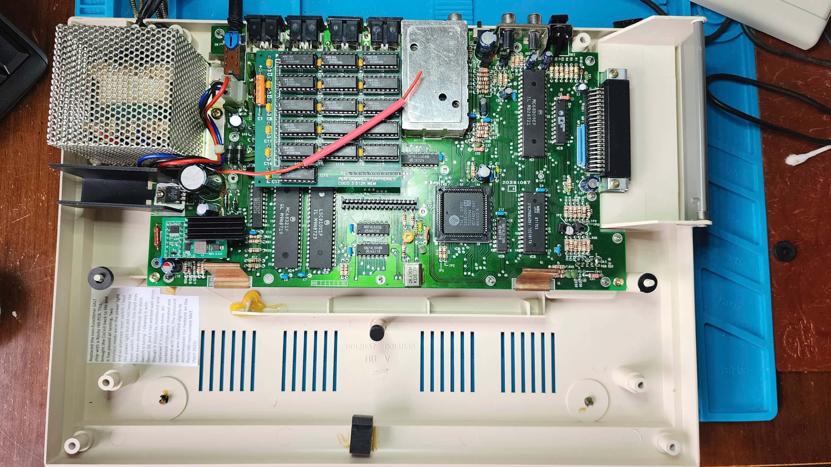
On initial power-up, I was greeted with a blank green screen. Hitting the reset button(s) did not rectify the situation, so my first step was to download the original CoCo 3 Service Manual. My second step was to open up the machine to see if I could see anything that was immediately wrong. That’s when I was pleasantly surprised to see that it had the 512K daughter board installed. Hopefully it worked…
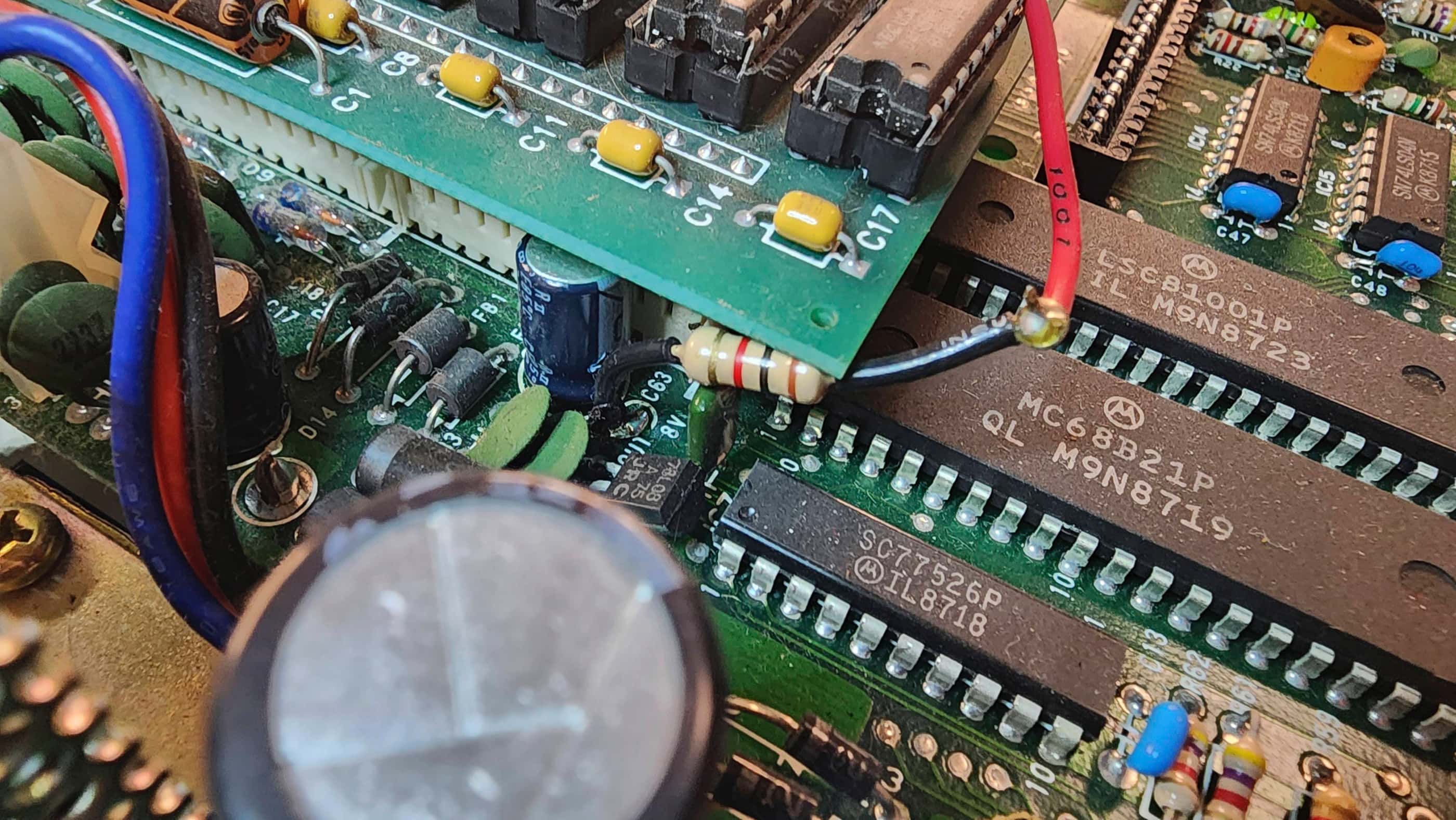
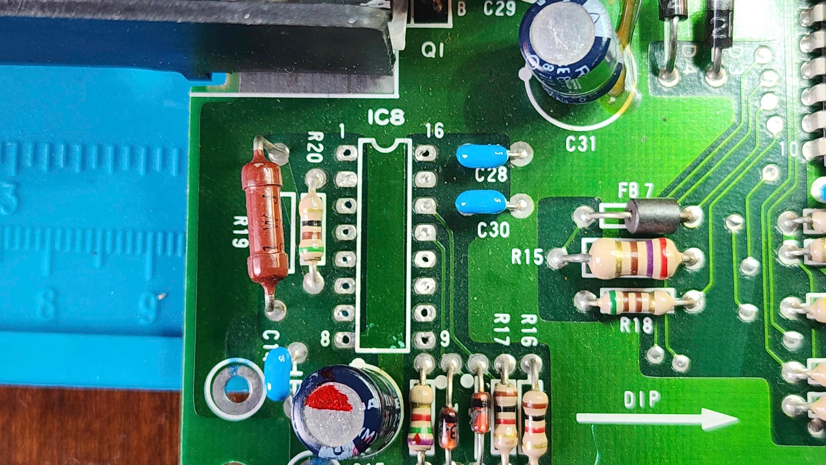
Not finding much on my initial inspection, I de-soldered and removed both the power light mod and reset switch mod just to eliminate any possibility that these were causing the failure. When the computer continued with the blank green screen, I began following the troubleshooting flowchart in the Service Manual. Through following the recommended voltage testing on TP1, I determined that the 5.4V that I was reading was higher than the spec range of 4.75 to 5.25V. My next step was to follow the flowchart to column ‘D’ which instructed me to test the voltage on the Collector of Q1. If the voltage was 1 volt higher than the Emitter, then the next step would be to replace the SALT chip.
Sure enough, the Collector was reading 10V while the Emitter was at 5V which meant that the SALT chip was likely at fault. The problem was, where do I find a replacement SALT? I could de-solder the one from my CoCo 2 and try that, but I really didn’t want to unless it was a last resort.
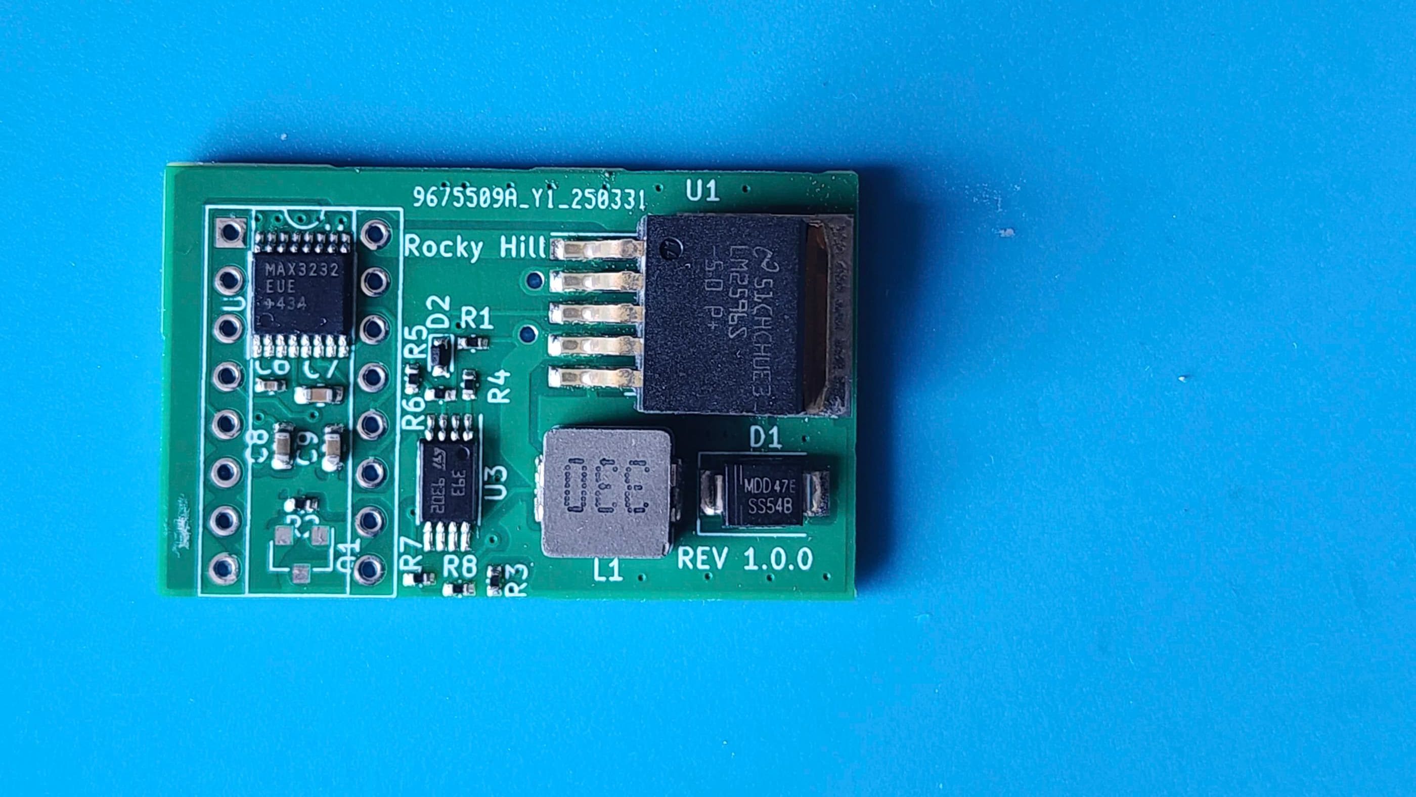
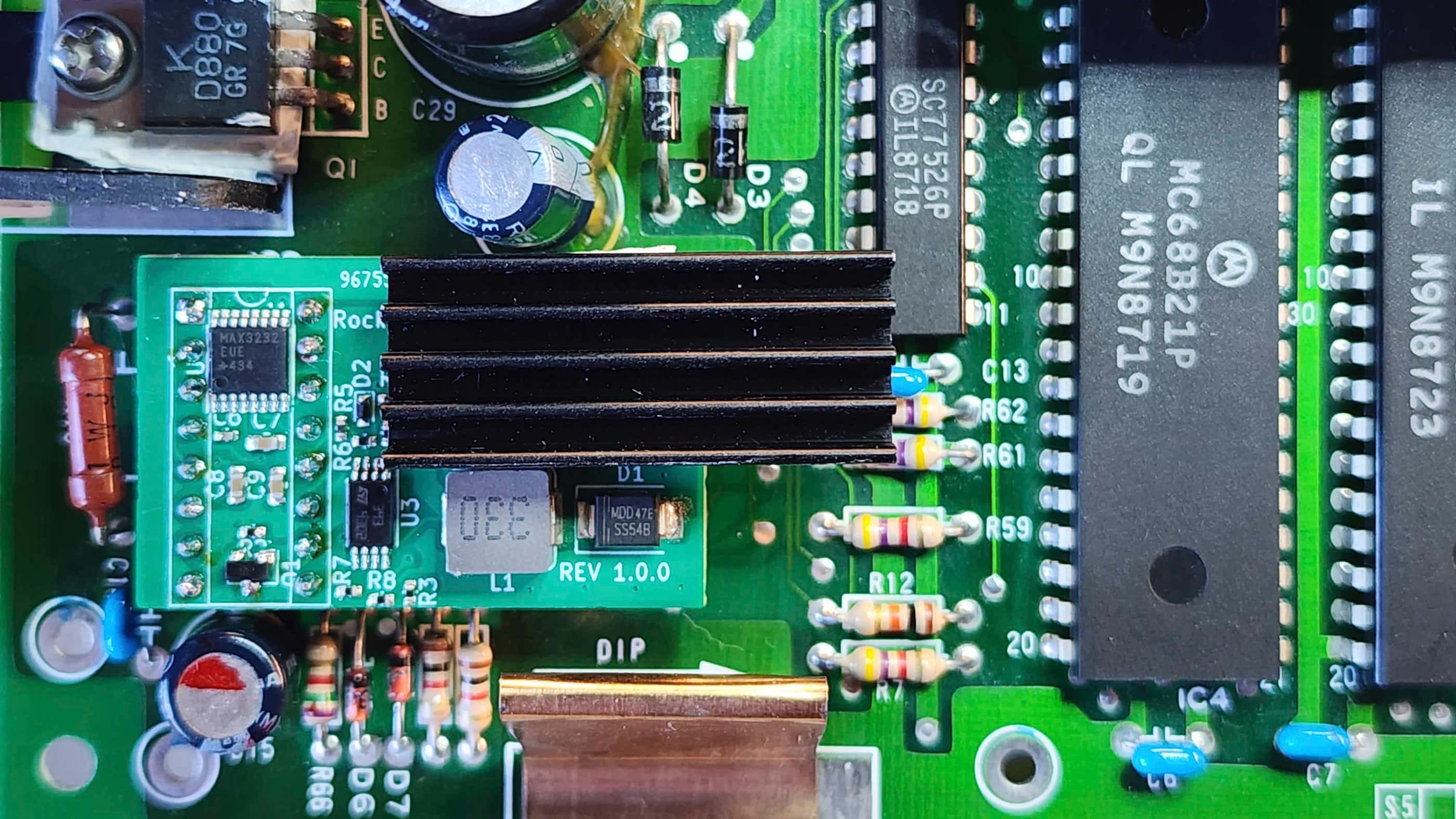
That’s when I discovered Rocky Hill’s PEPPER board, which is a SALT chip PCB replacement. Following his exact instructions in GitHub and using his prepopulated BOM, I placed an order with JLCPCB. Unfortunately, they were out of stock of the MMBT9014C transistor; however, I was able to secure it from another source.
Having JLCPCB solder the components to the board at the factory meant that all I had to do when it arrived, was solder on the missing transistor and the header pins. After de-soldering the original SALT chip and then adding a new socket, I was ready to see if the v 1.0 PEPPER board solved the problem…
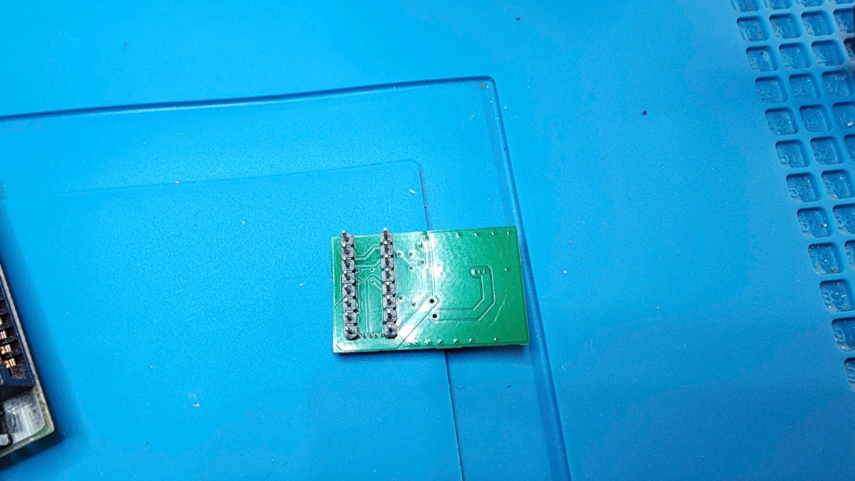
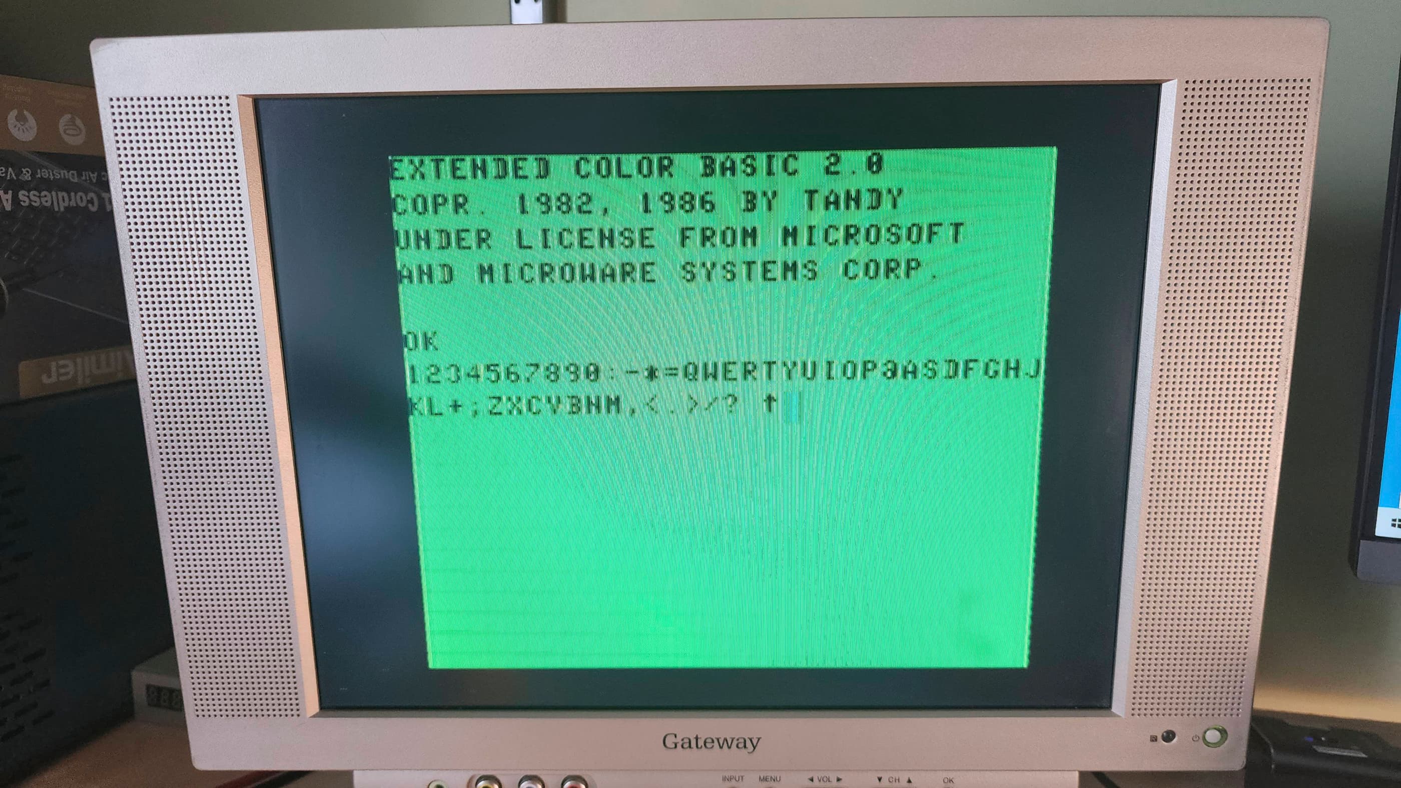
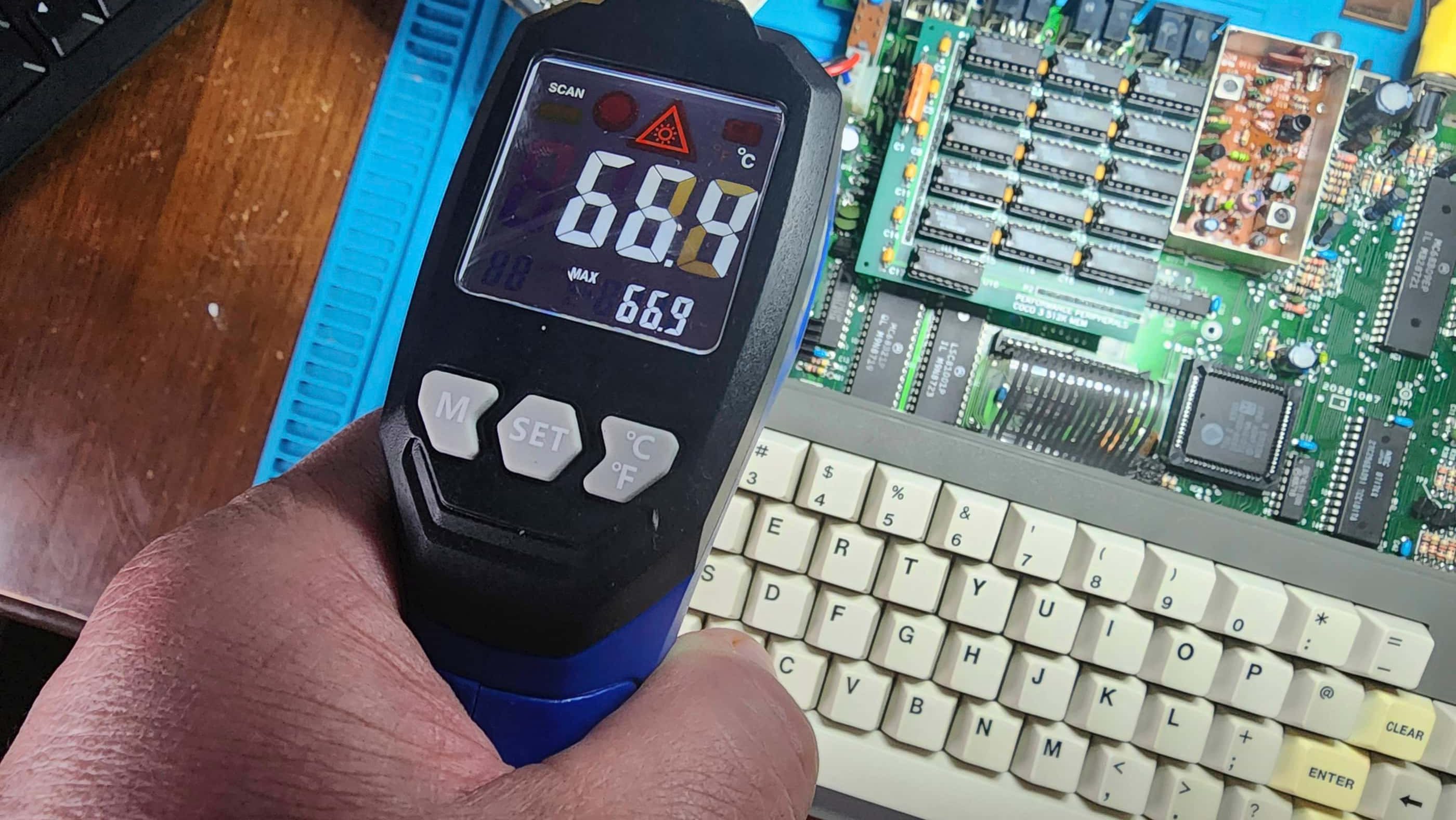
It did! 😀 The CoCo3 sprang to life when I powered it on and I could not find any remaining faults after testing. Following the lead in Rocky Hill’s videos, I added a heatsink as U1 – the LM2596S-5 switching regulator – runs extremely hot. I’ll also note that the pins need to be trimmed so that the board fits flush with the socket and that the heatsink needs to have a low enough profile to allow it to fit underneath the keyboard.
I also added two homemade rubber feet underneath the PEPPER to prevent it from being accidently disconnected from the socket if downward pressure were to be exerted on the opposite end of the board. I also added a slightly thicker rubber washer to the keyboard standoff to ensure that when fully reassembled, the keyboard would not interfere with the heatsink and board.
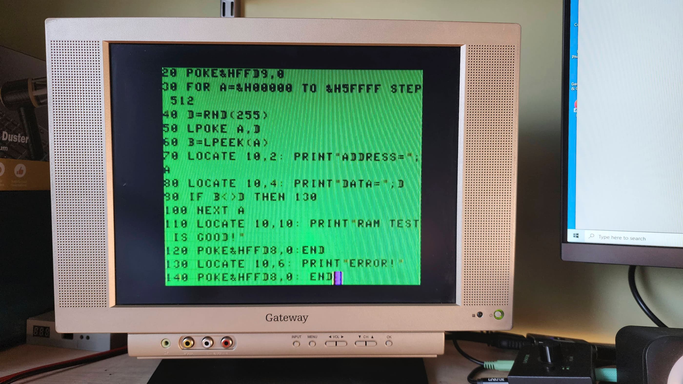
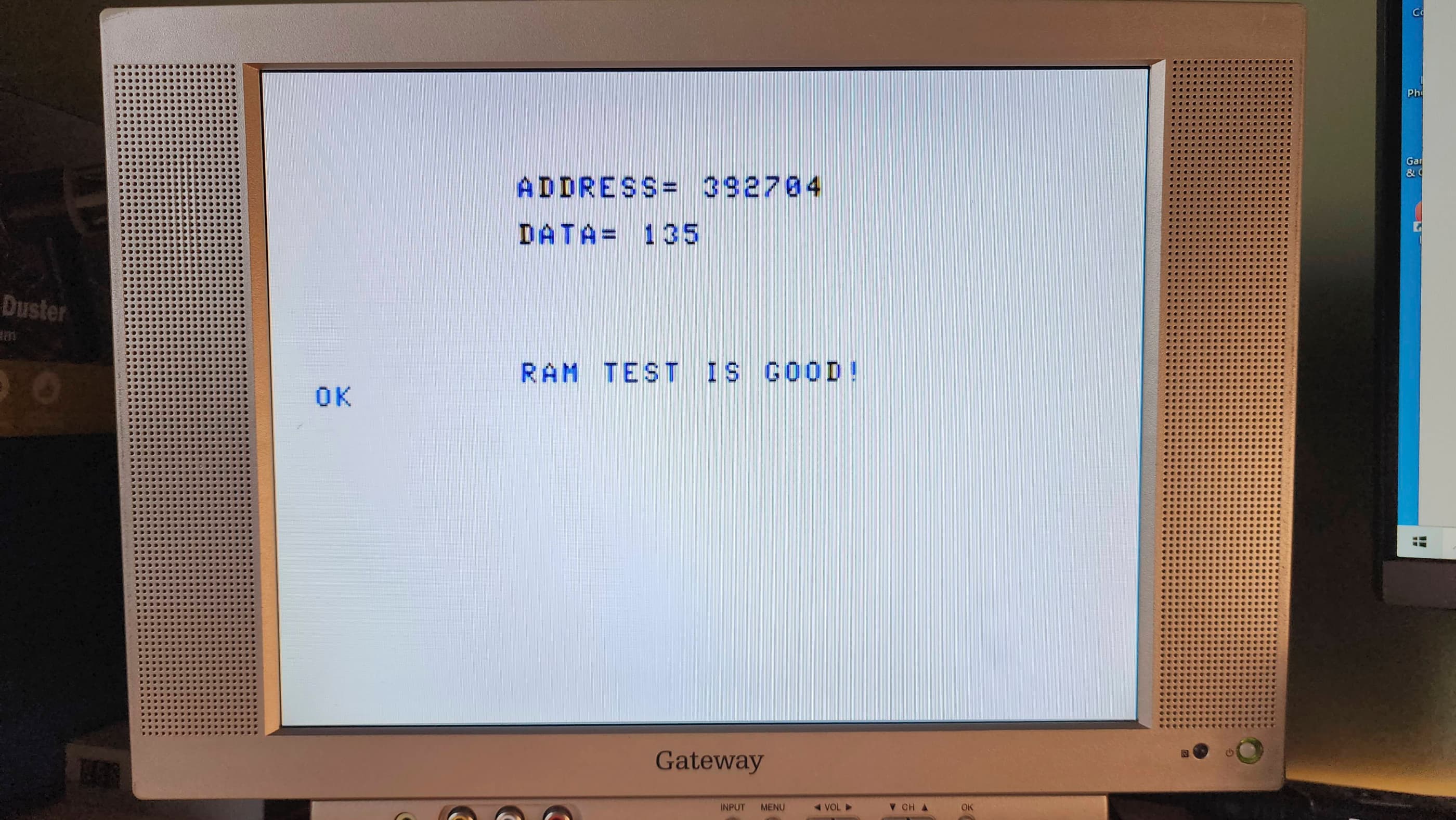
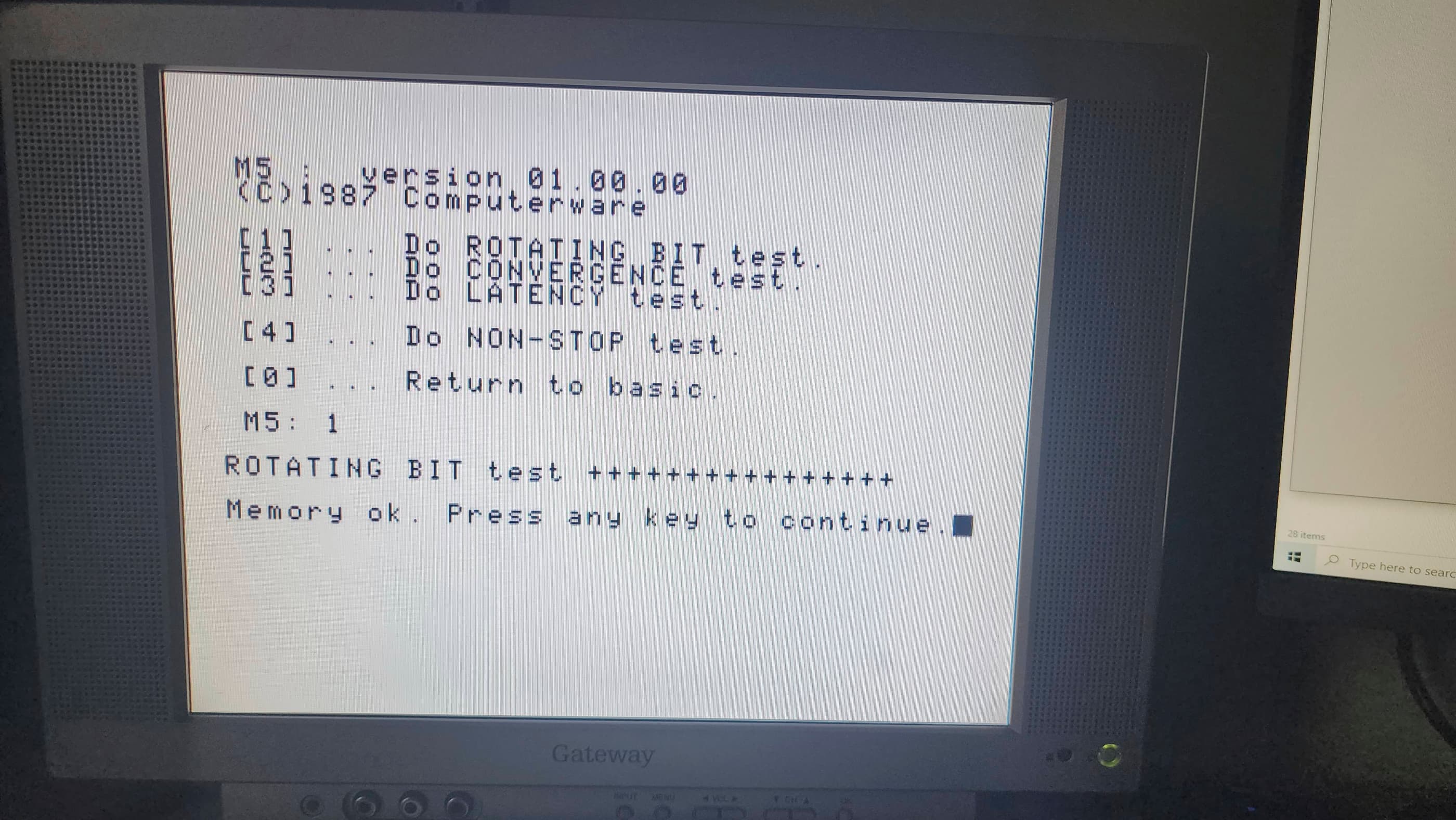
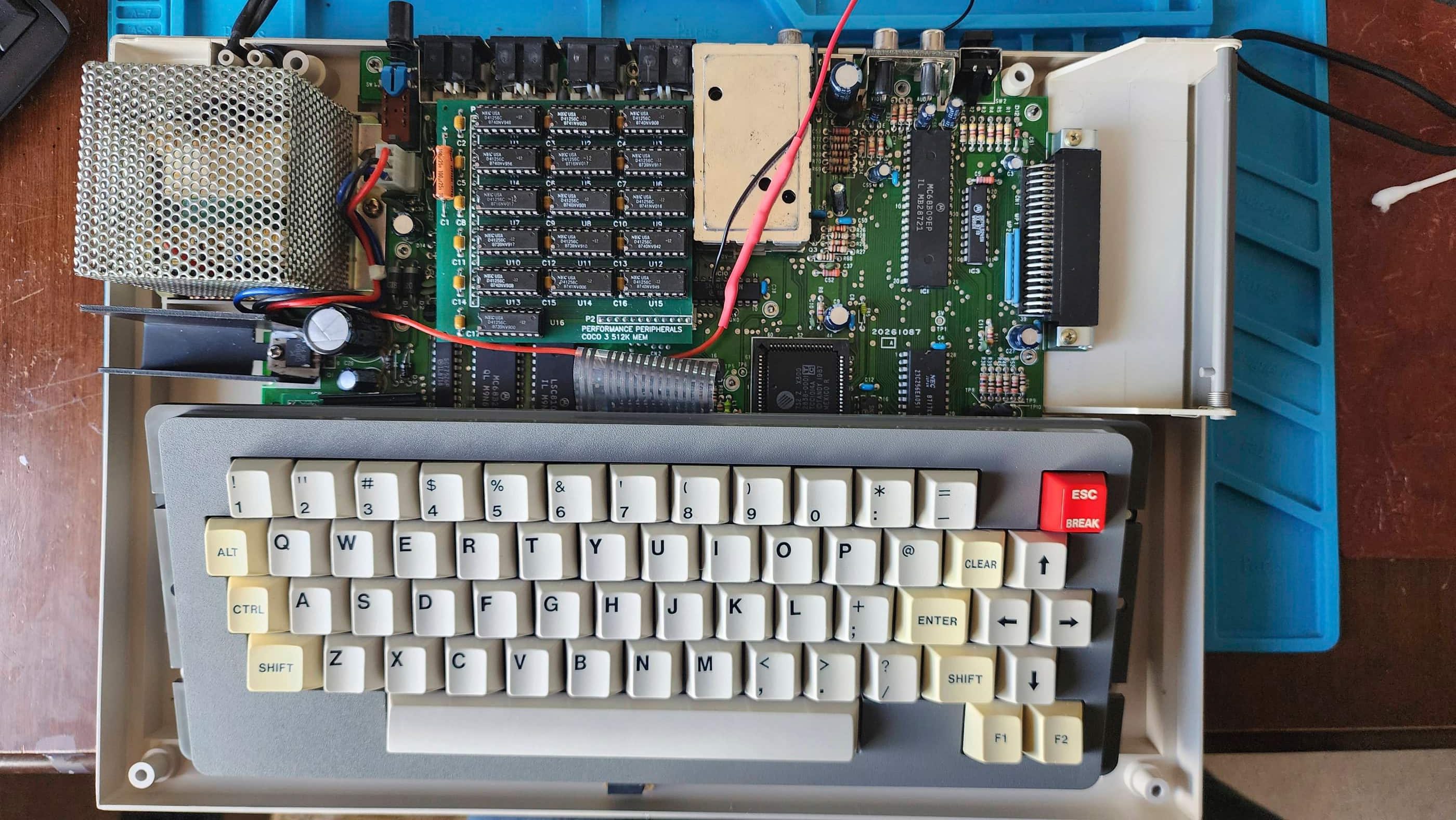
Now that I had a fully working CoCo 3, I began testing the RAM with various programs along with trying to figure out why a second reset button was added. What I discovered was that occasionally, the factory reset switch would remain in reset for an extra few seconds after being pushed. I reasoned this may be due to a lack of separation between contacts from either dirt / corrosion or the switch wearing out – or both.
My attempt to rectify this was to apply a liberal amount of Deoxit D5 and after further testing, I could not replicate the glitching so hopefully the problem was solved. For this reason, I didn’t reinstall the second reset switch mod; however, I did reinstall the power light mod, though I extended the 8V line to attach underneath the board and I also covered the 1K resistor with heat shrink to prevent shorting.
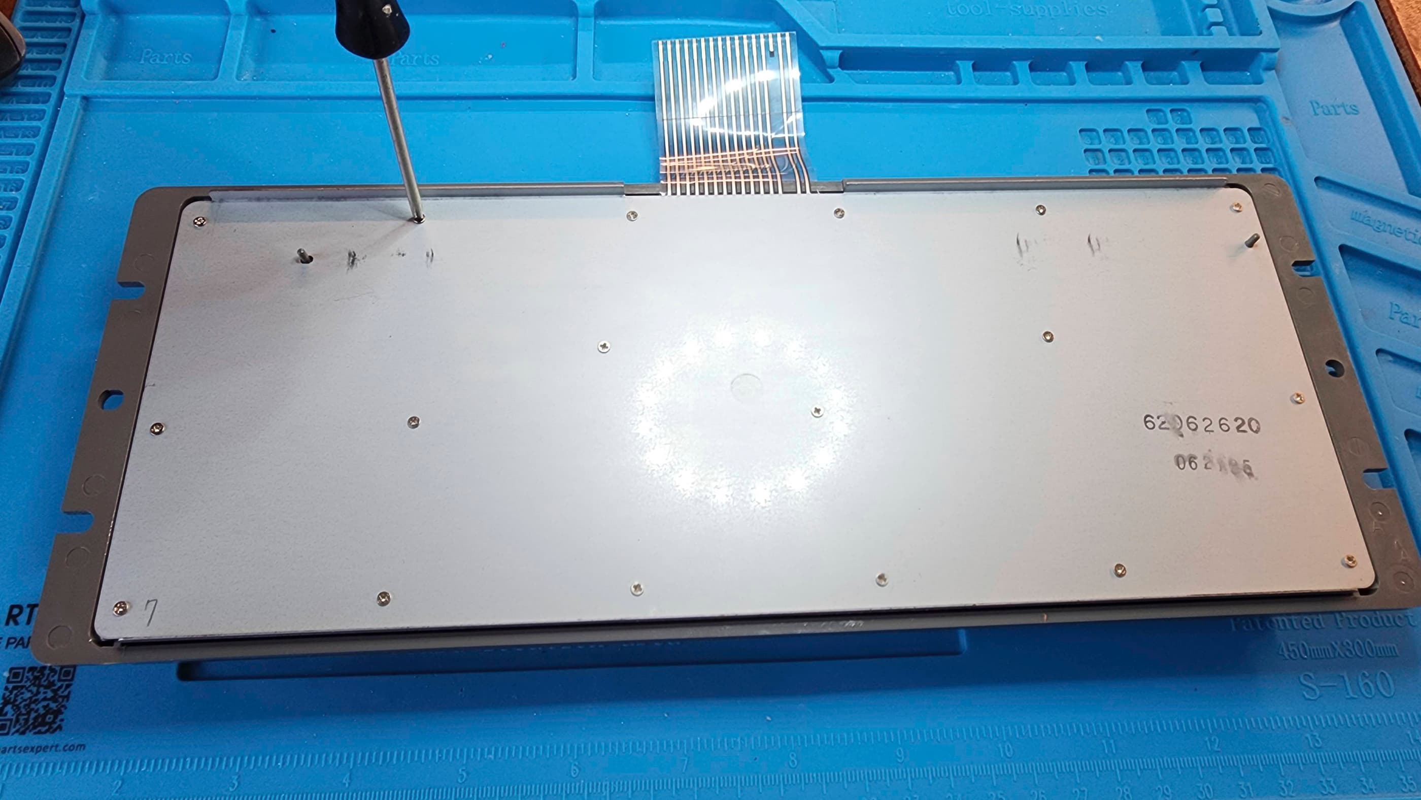
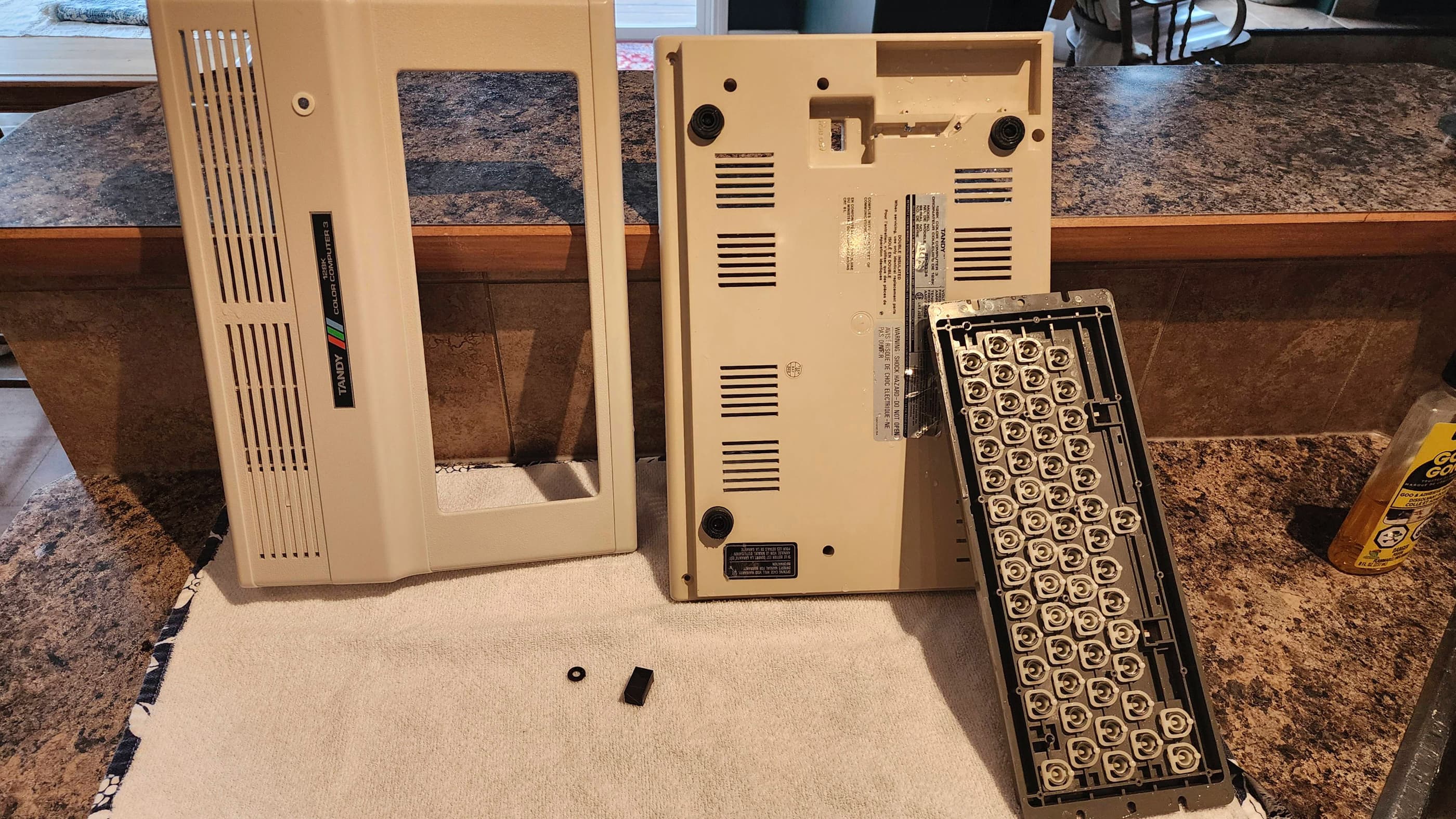
Finally, I gave the board a thorough cleaning as it was quite dirty. I also removed all the socketed chips, treated them with Deoxit D5, and reseated them. I then turned my attention to cleaning the keyboard and the case and when this was done, I reassembled the machine and paired it with a Tandy joystick. Another round of testing revealed that the keyboard and everything else appeared to be working correctly. I’m now the proud owner of a working CoCo3 thanks to the tremendous efforts – and generosity – of Rocky Hill. 🙂
Parts & Products Used: 99% isopropyl alcohol; Chemical Guys Natural Shine; Deoxit D5; Rocky Hill’s PEPPER board; aluminum heatsink;


You must be logged in to post a comment.