
First Generation (1972 – 1980)

Atari Super Pong
Years (1976 – 1977)
Interesting Fact: Super Pong was Atari’s second console and came as a the follow-up to their 1975 release of Pong (C-100). Unlike Pong which only had one game, Super Pong featured 4 games and automatic scoring. (source) When Atari released the original Pong in 1975, the development of a single chip or ‘Pong-on-a chip’ was revolutionary and represented the most powerful chip to date for use in a consumer product. (source)
Condition When Acquired: Partially Functional – controller issues
Current Condition: Fully Functional

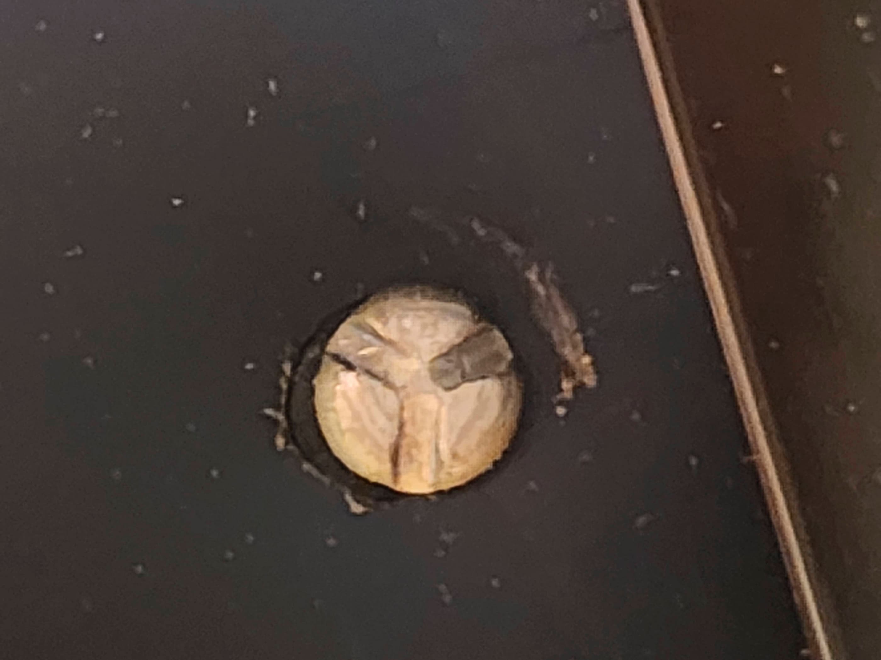


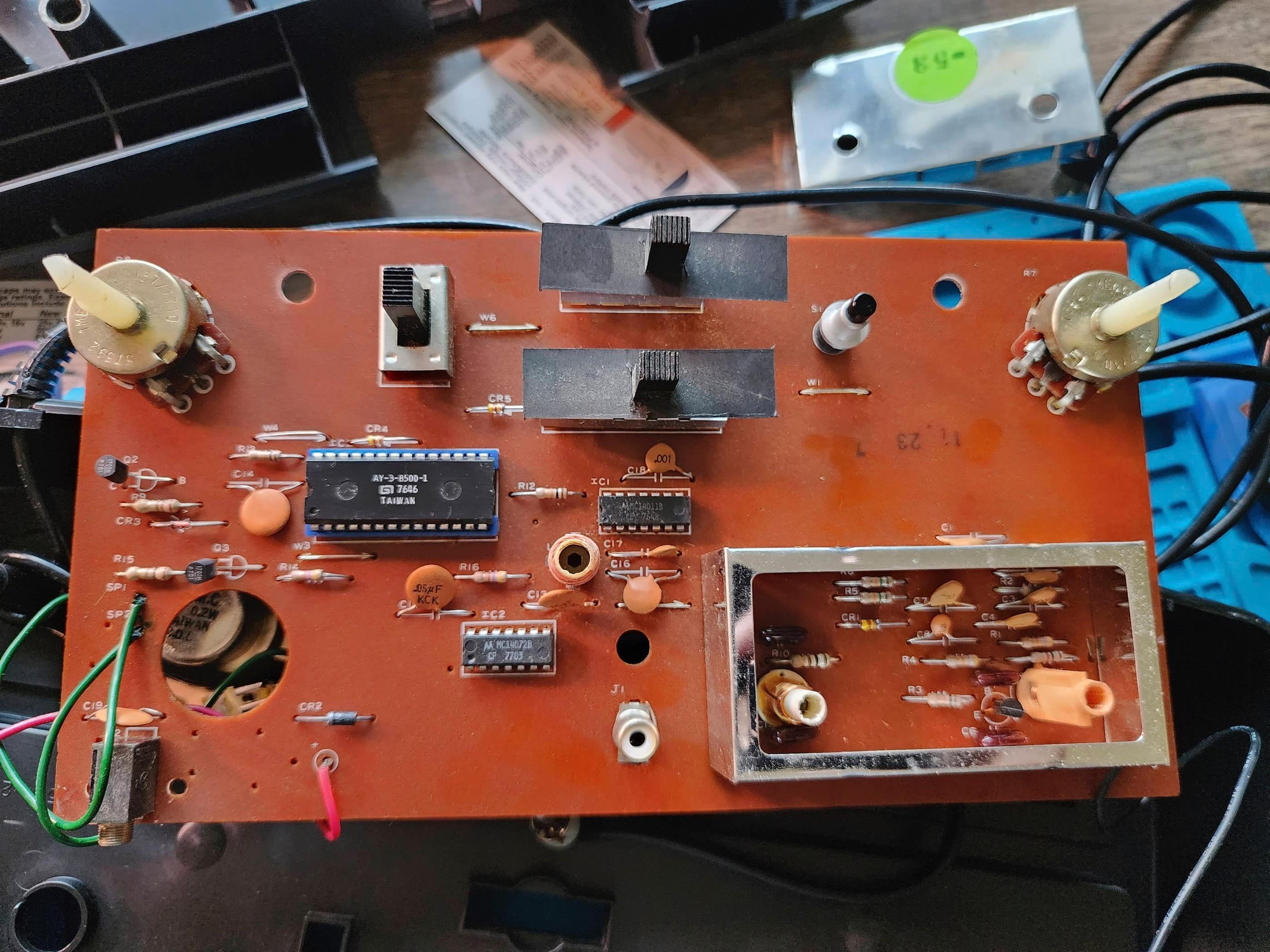
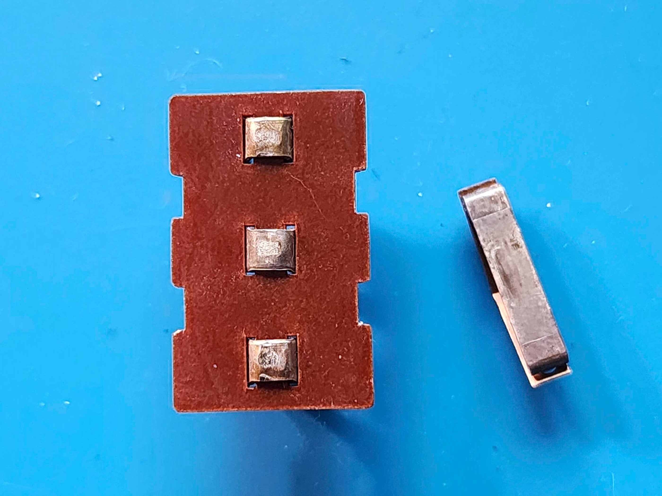
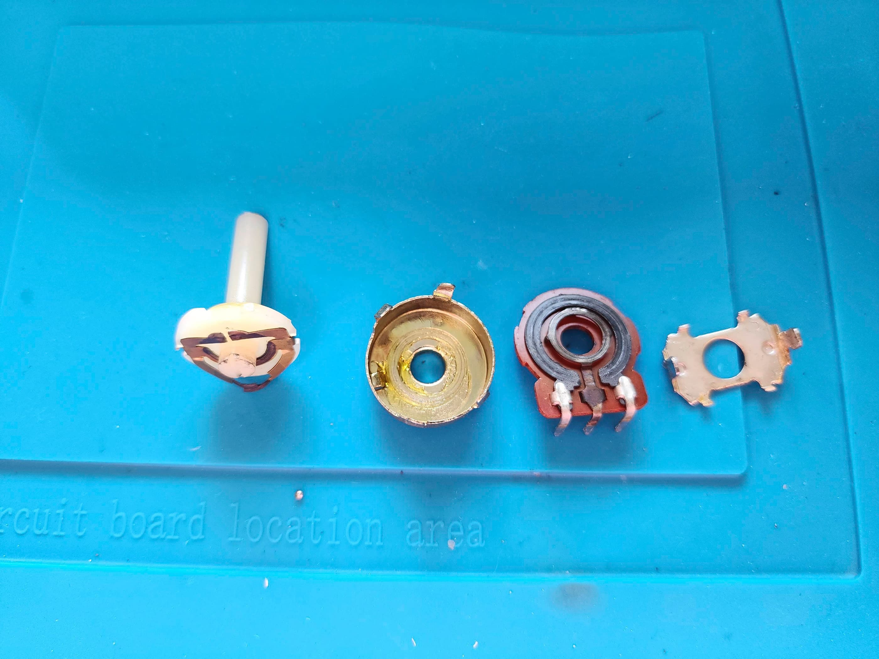
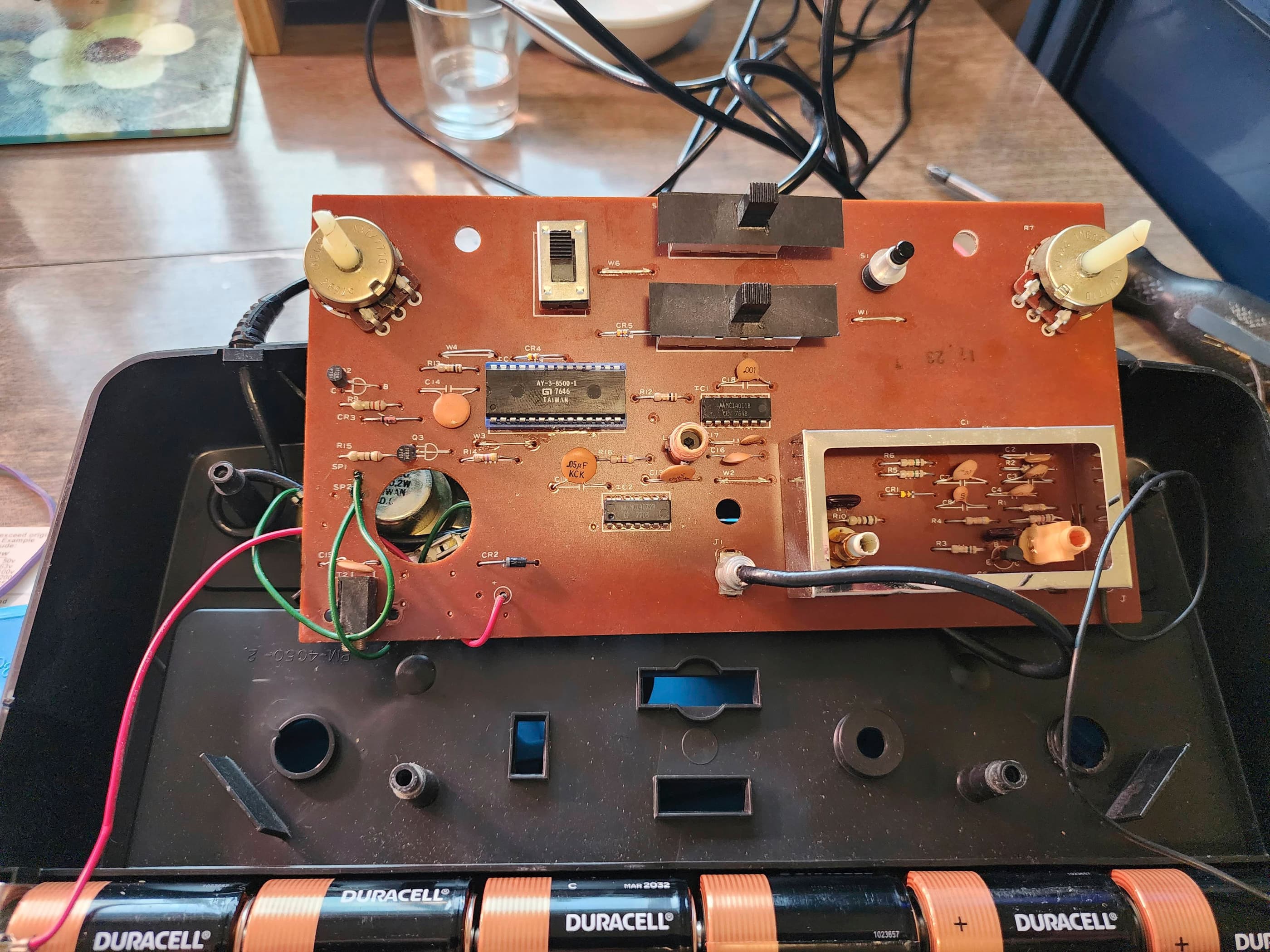
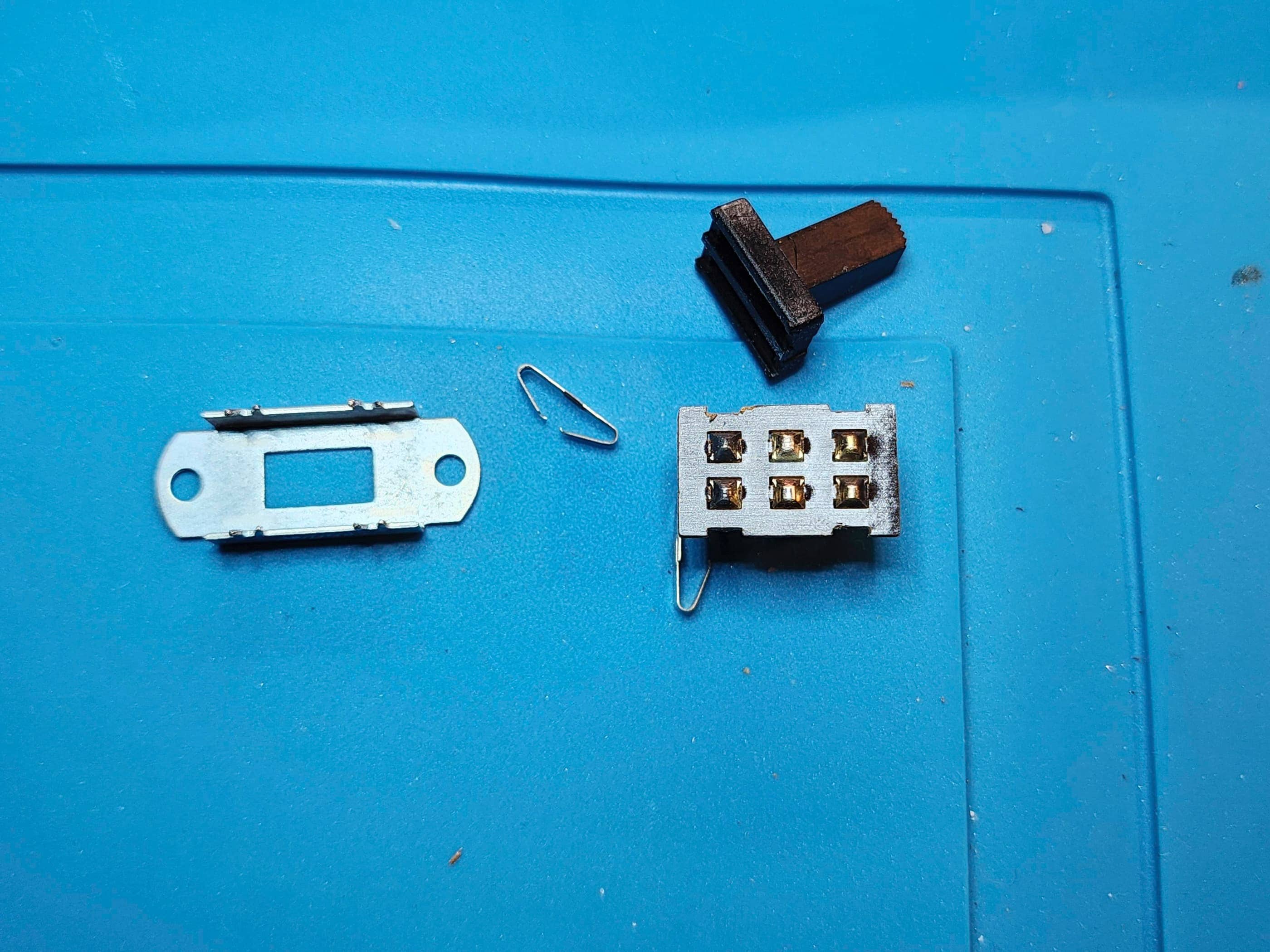
Project Details: This unit came to me in good condition but was unplayable because of skittish paddles when the controllers were rotated. As I had used brand new batteries to test the unit, this led me to believe that the contacts in the potentiometers were dirty. No problem, right? 🙃 Well, I was more than surprised to discover that Atari used two 1/4″ (#10) tri-groove (or tri-wing or Holt tri-wing) security screws to fasten the unit together. Not having this socket, I briefly tried using needle-nose vice grips to loosen the screws. However, when that didn’t happen with ease, I gave up because I was at risk for gouging the plastic on the case. I then contemplated drilling into the screw head and using either a tap or reshaping the slots to fit a normal screwdriver. This also wasn’t my first choice, so I looked on Atari Age and noted some of the creative DIY tri-groove tools that members had made. I then looked online for a socket and was shocked to see how expensive they were. I eventually found one at Grainger Canada for ~$30.00 and ordered it online. Once it arrived, it made removing the screws a simple task, proving the old adage that “you need the right tool for the job.”
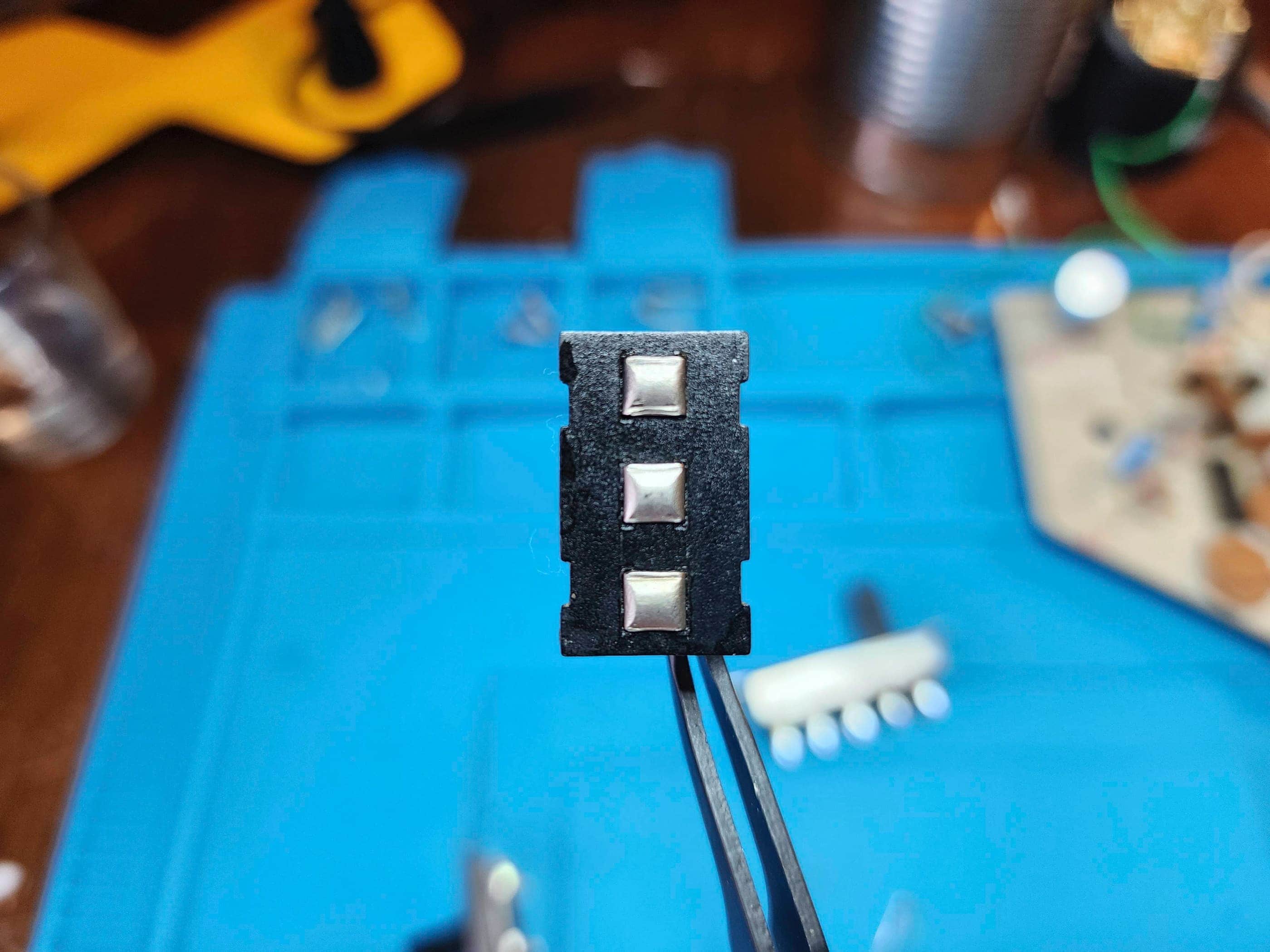
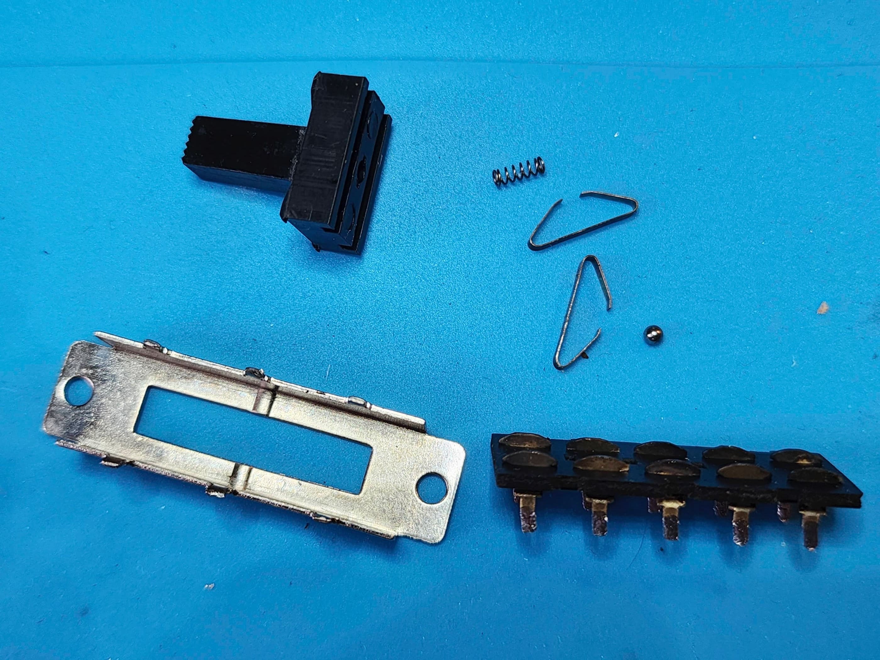
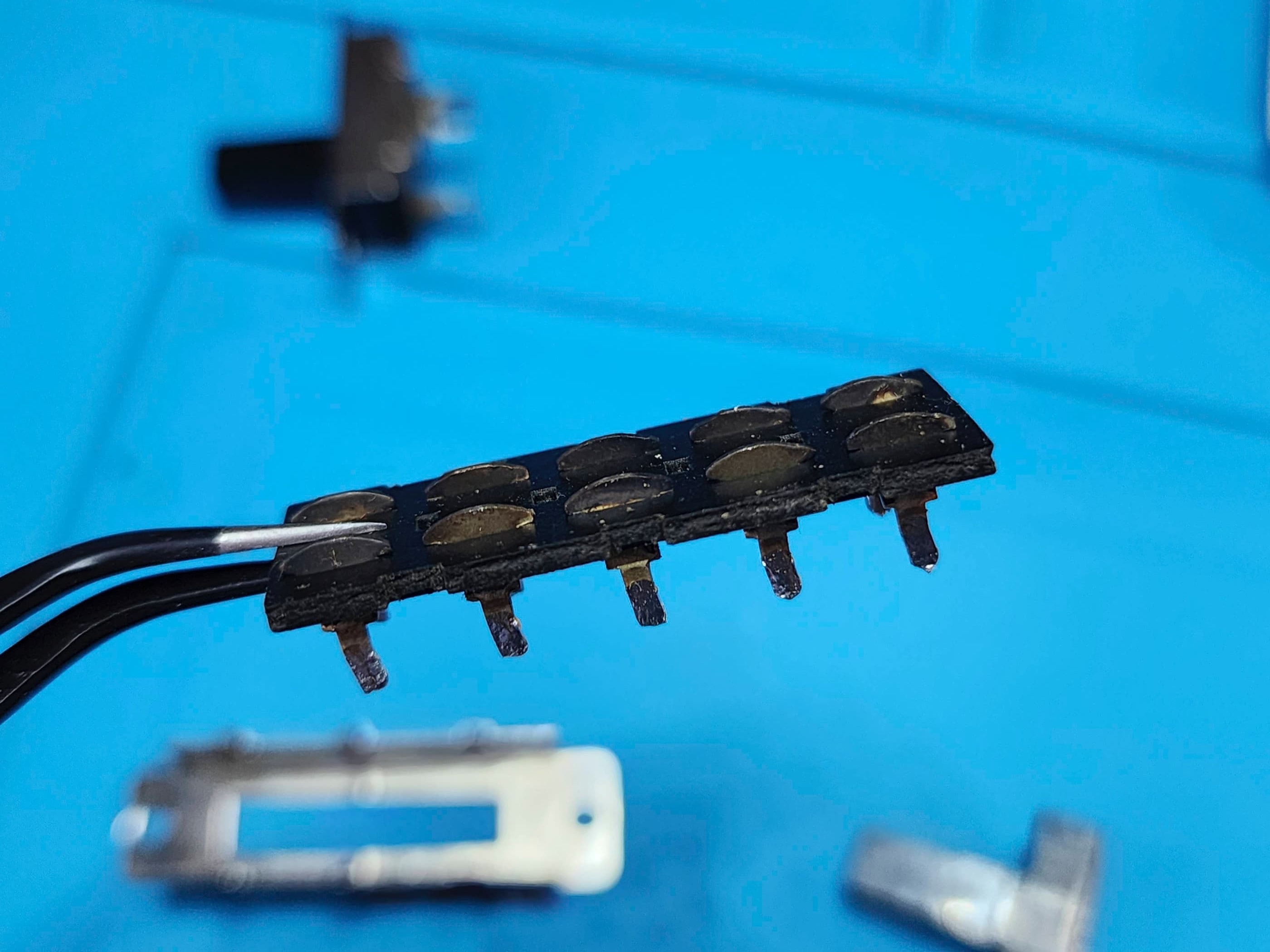
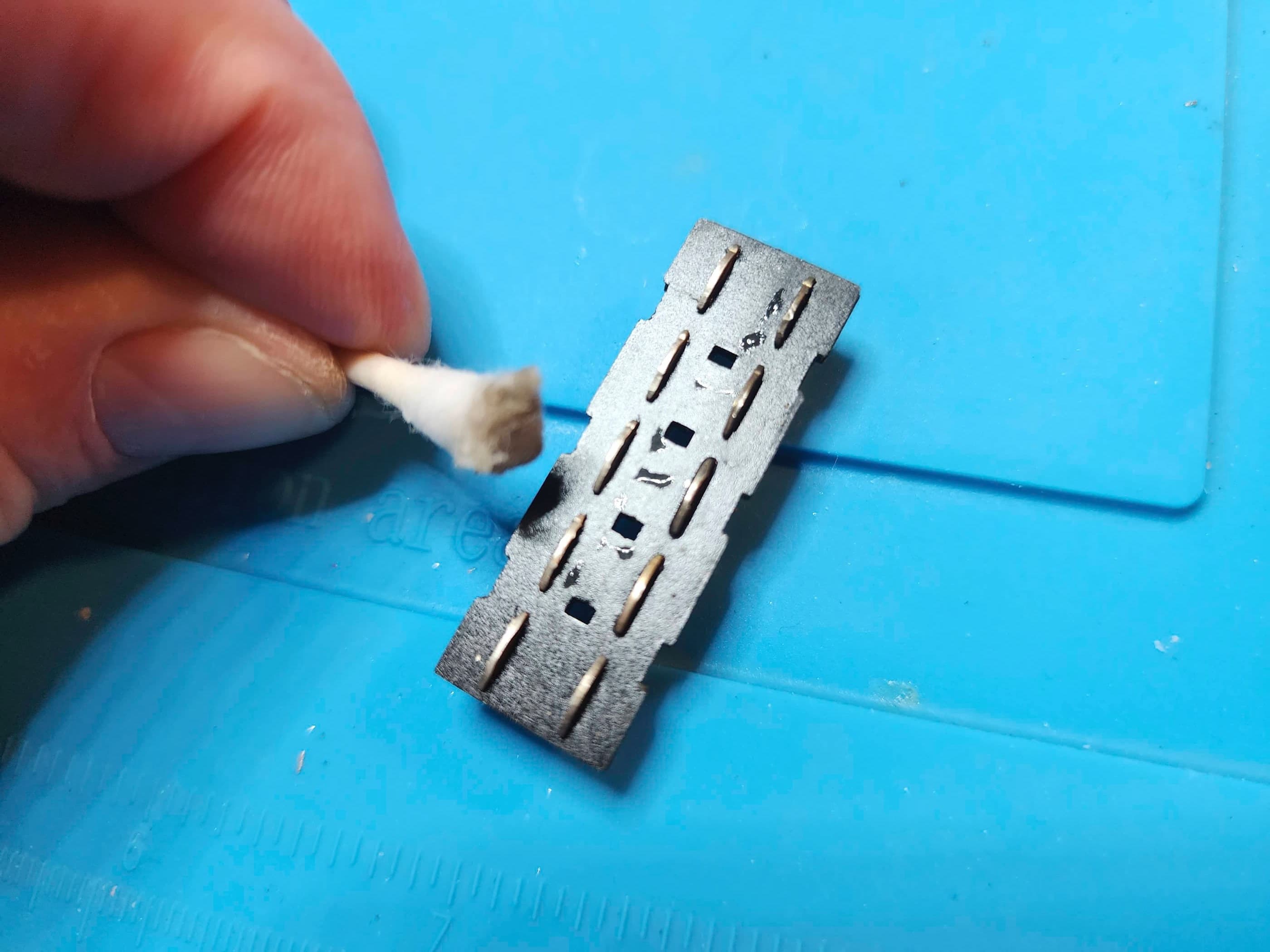
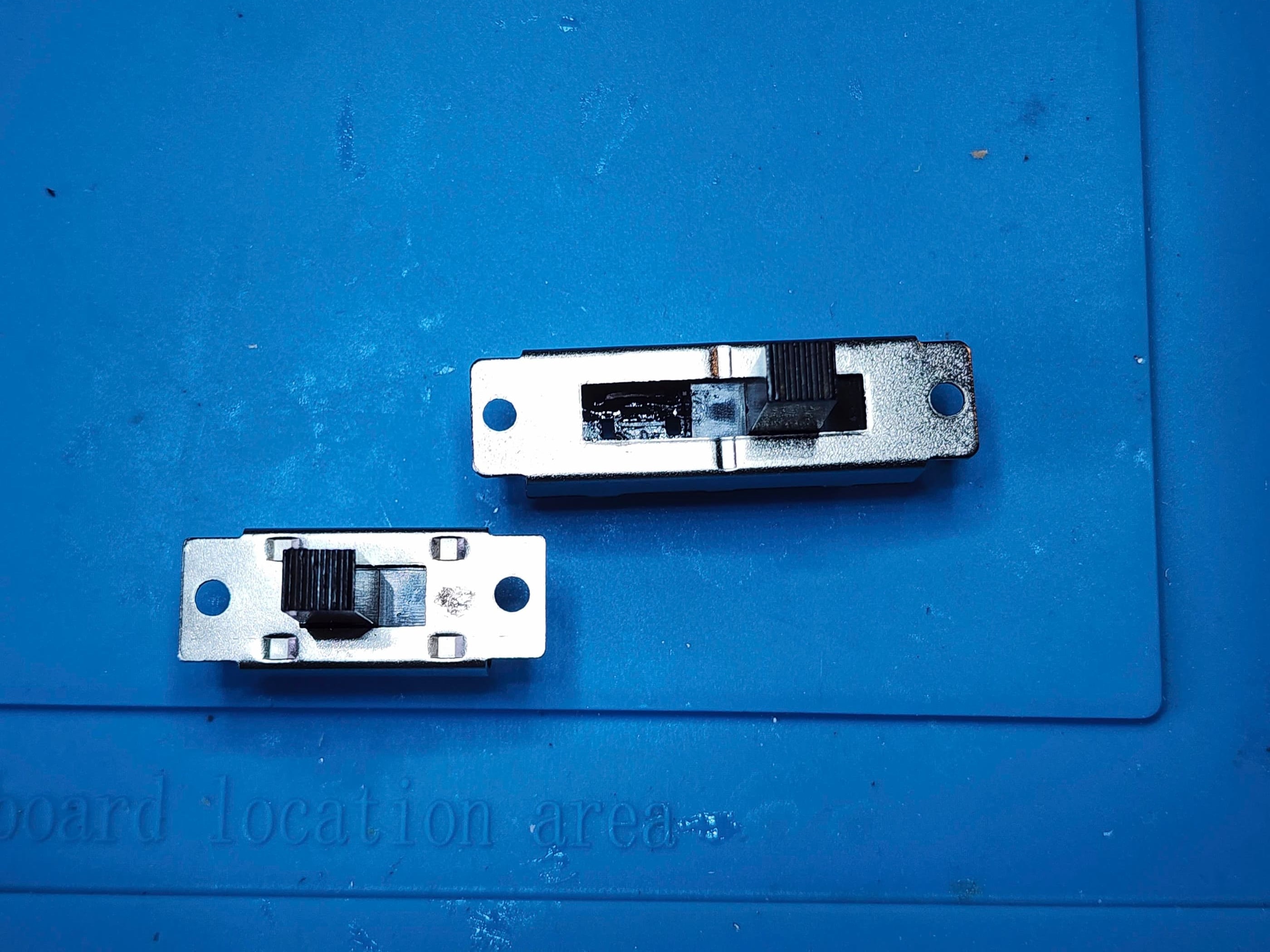
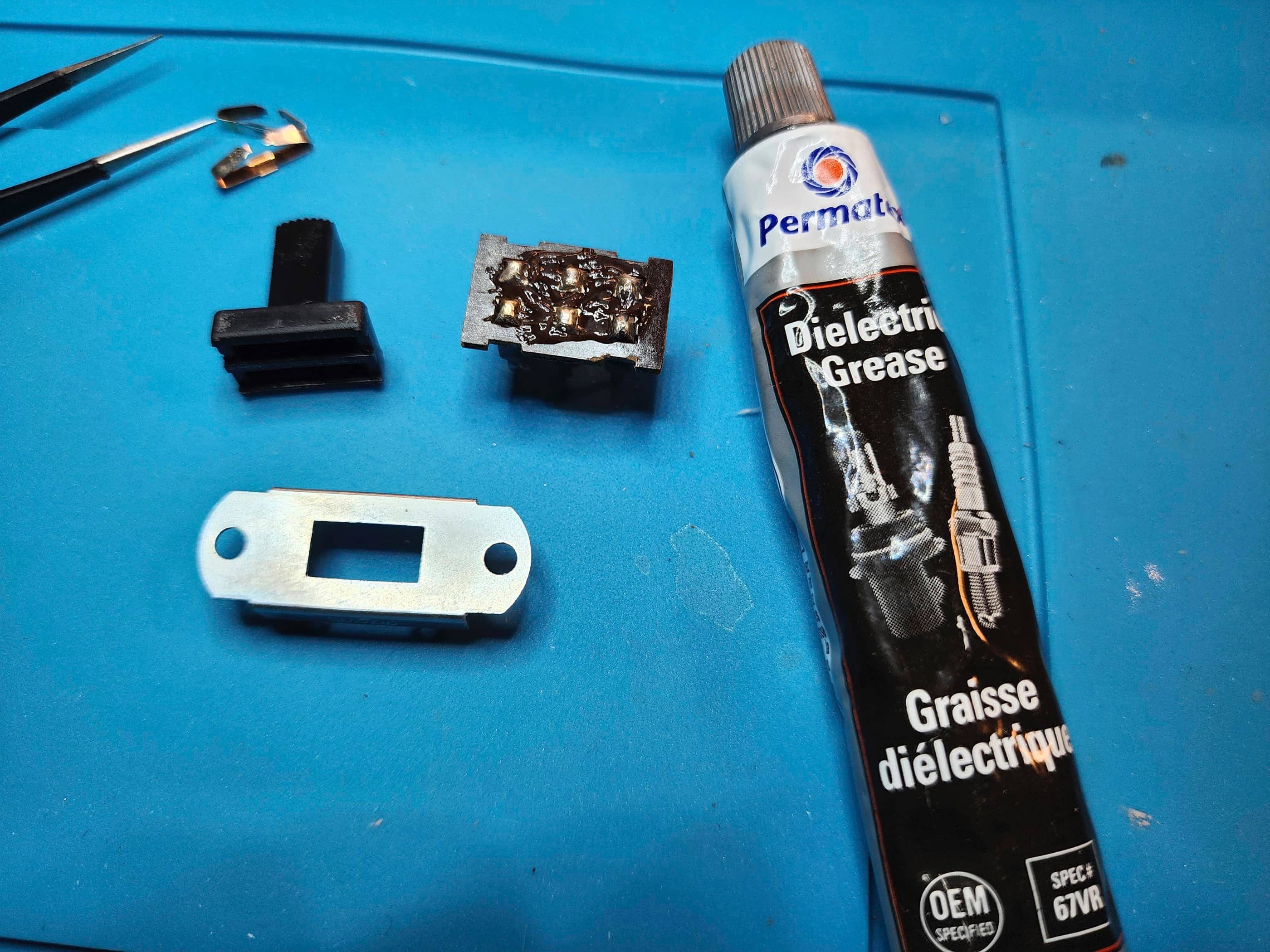
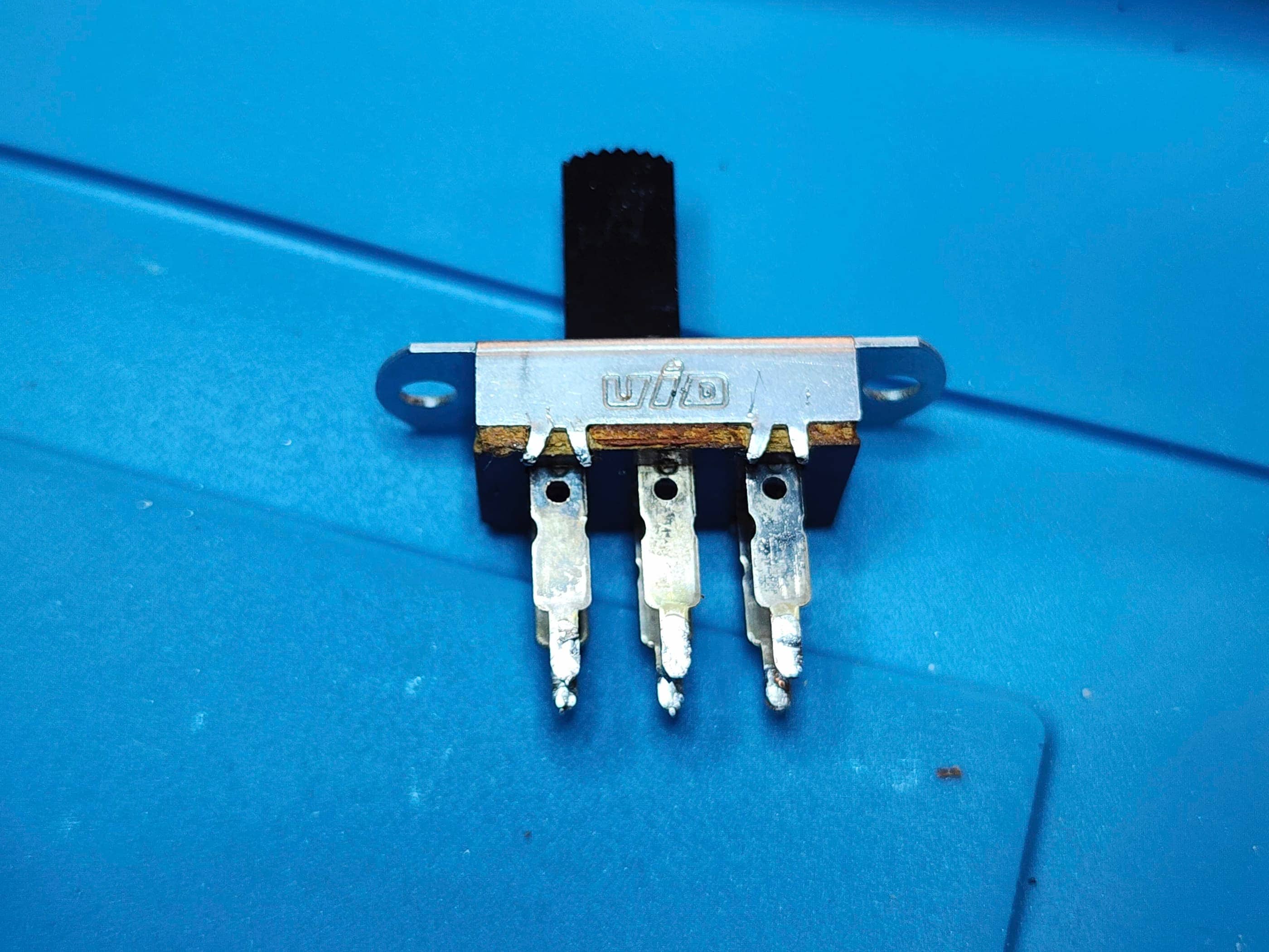
Once open, I desoldered the paddle potentiometers, disassembled them, and gave the contacts a thorough cleaning. They were dirty! I then reassembled and soldered them back onto the board where I discovered that I had put the left pot back together incorrectly as no paddle appeared on the screen. Instead of desoldering it, I just bent it forward and disassembled and reassembled it, so note to self: this will be a time saver in the future. Once it was back together a quick test showed that the system was now working correctly. I then took apart the power switch and the game select switch and cleaned the contacts. I also cut the wires between the battery / compartment and the board so that I separate the console pieces. I then cleaned the parts, applied dielectric grease and reassembled the switches, replaced the wires, and put the entire unit back together. An application of Natural Shine brought back the console’s original luster and after further testing, I determined that all the switches, power sources (including the power adapter), and pots were working as they should. It is now a fully functioning system.
Parts & Products Used: 99% isopropyl alcohol; dielectric grease; Chemical Guys Natural Shine; EAZYPOWER SAE 1/4″ Tri-Groove bit #1-4 Model#35933

Coleco Telstar Alpha
Years (1977 – 1978)
Interesting Fact: In 1932, the Connecticut Leather Company (Coleco) began supplying materials for shoe repair. Post-war, the company expanded into toys and entered the emerging ‘Pong-on-a-chip’ video game market in 1976 with its Telstar system. Coleco lucked out by placing its chip order earlier than other companies and when a shortage occurred, Coleco was one of only a few companies to receive their shipment, allowing them to survive that initial year. The Telstar Alpha was the third of fourteen different Telstar models produced between 1976 and 1978. (source)
Condition When Acquired: Non-Functional (DOA)
Current Condition: Fully Functional


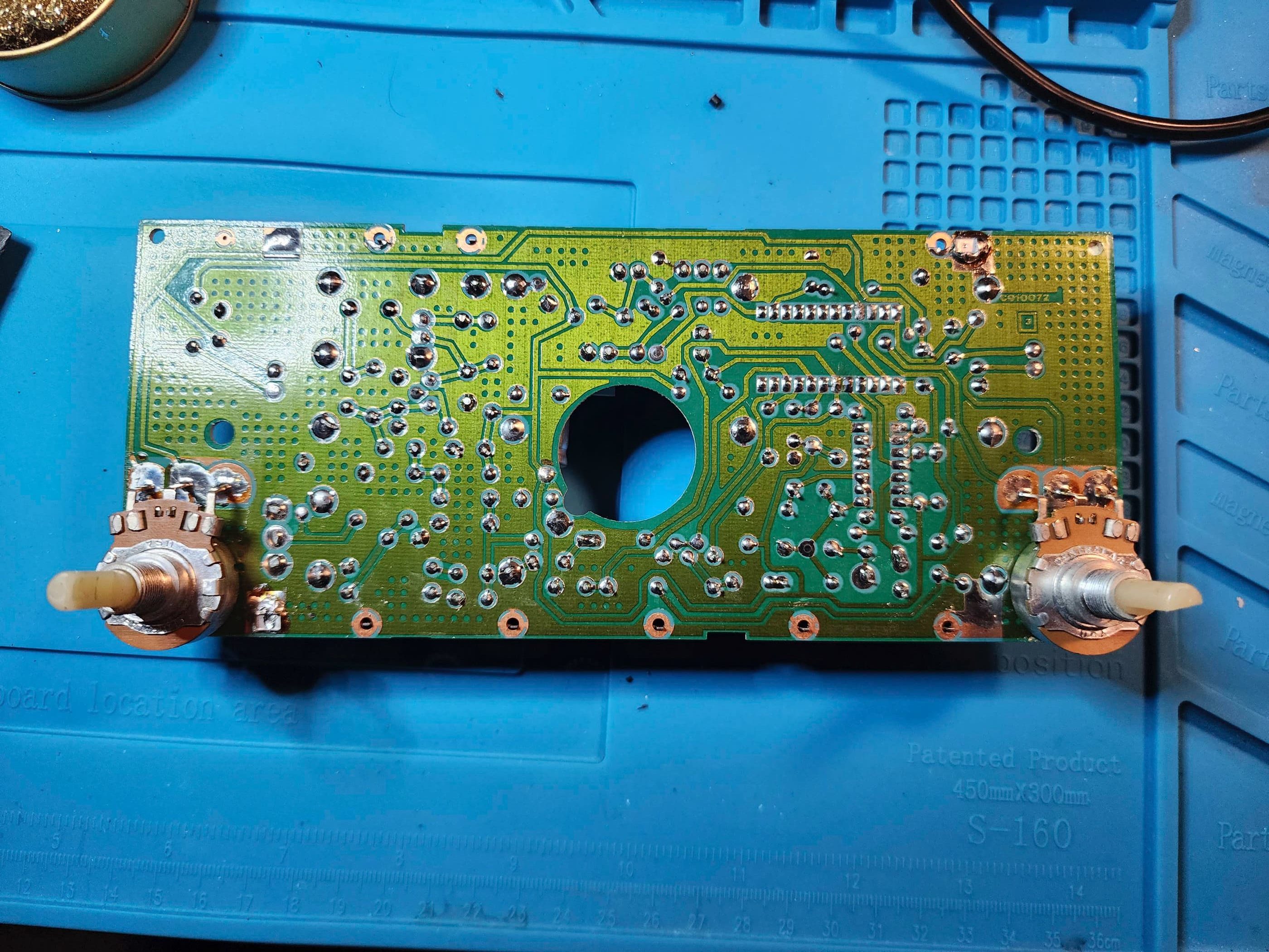
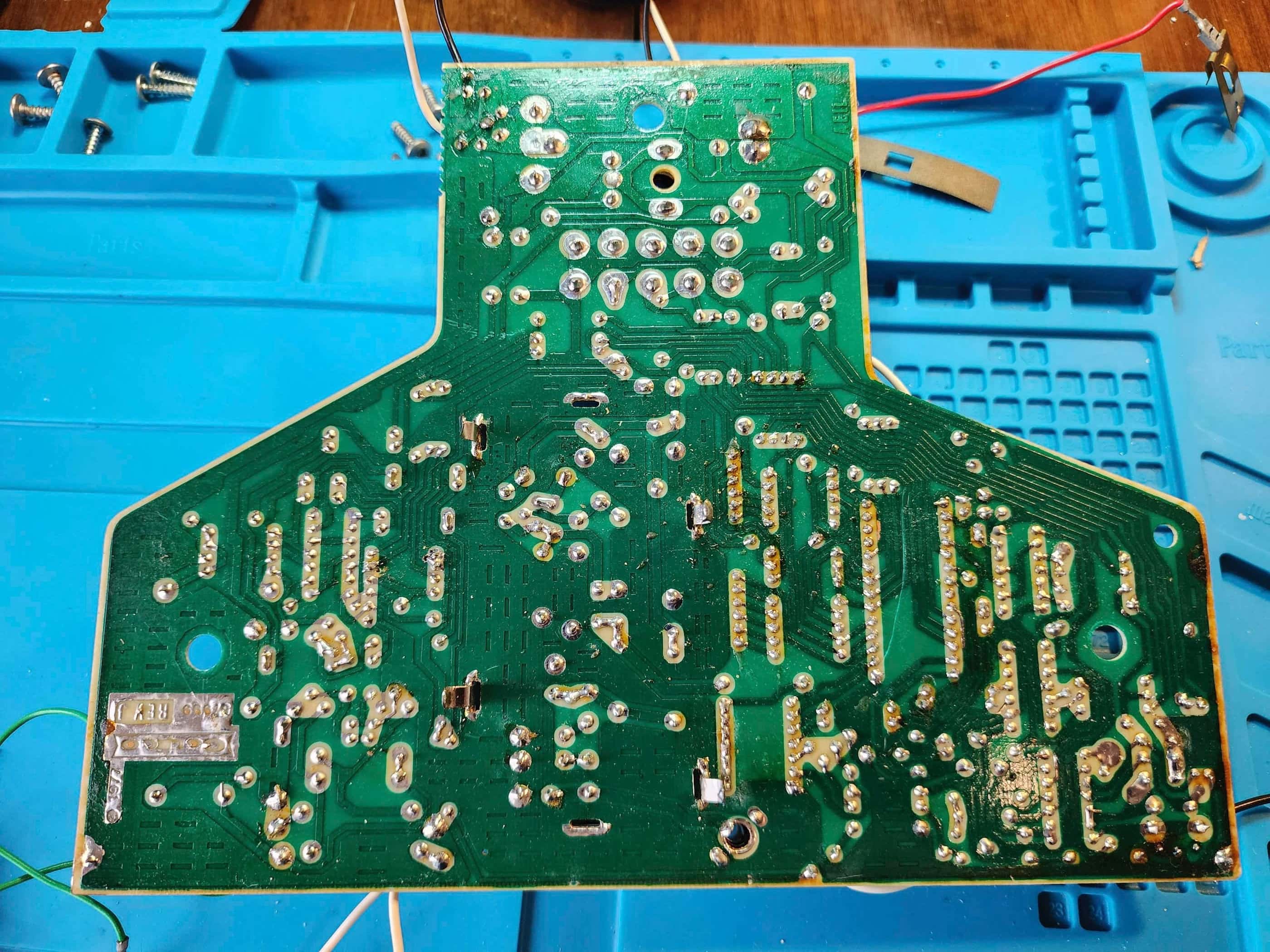
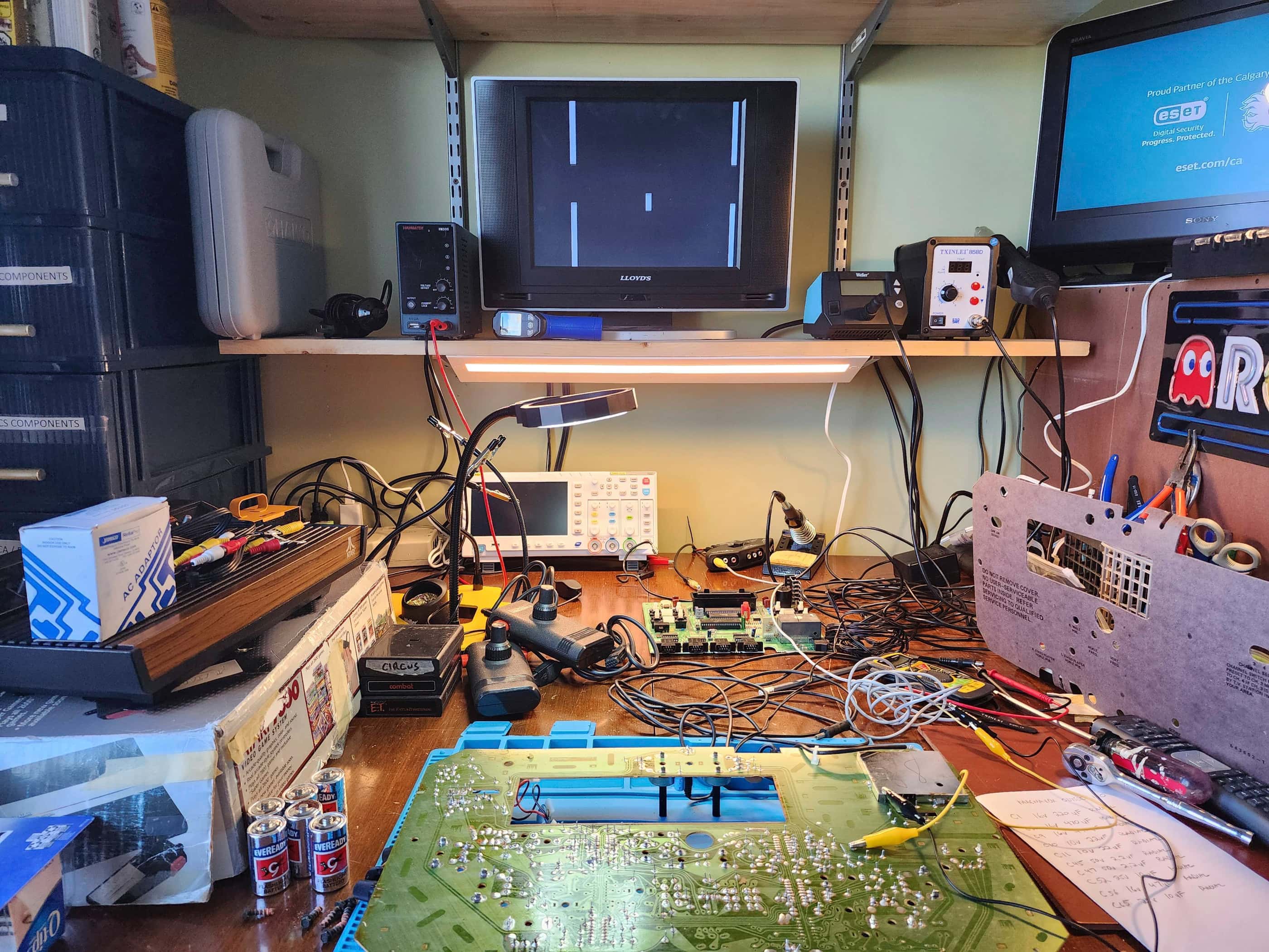
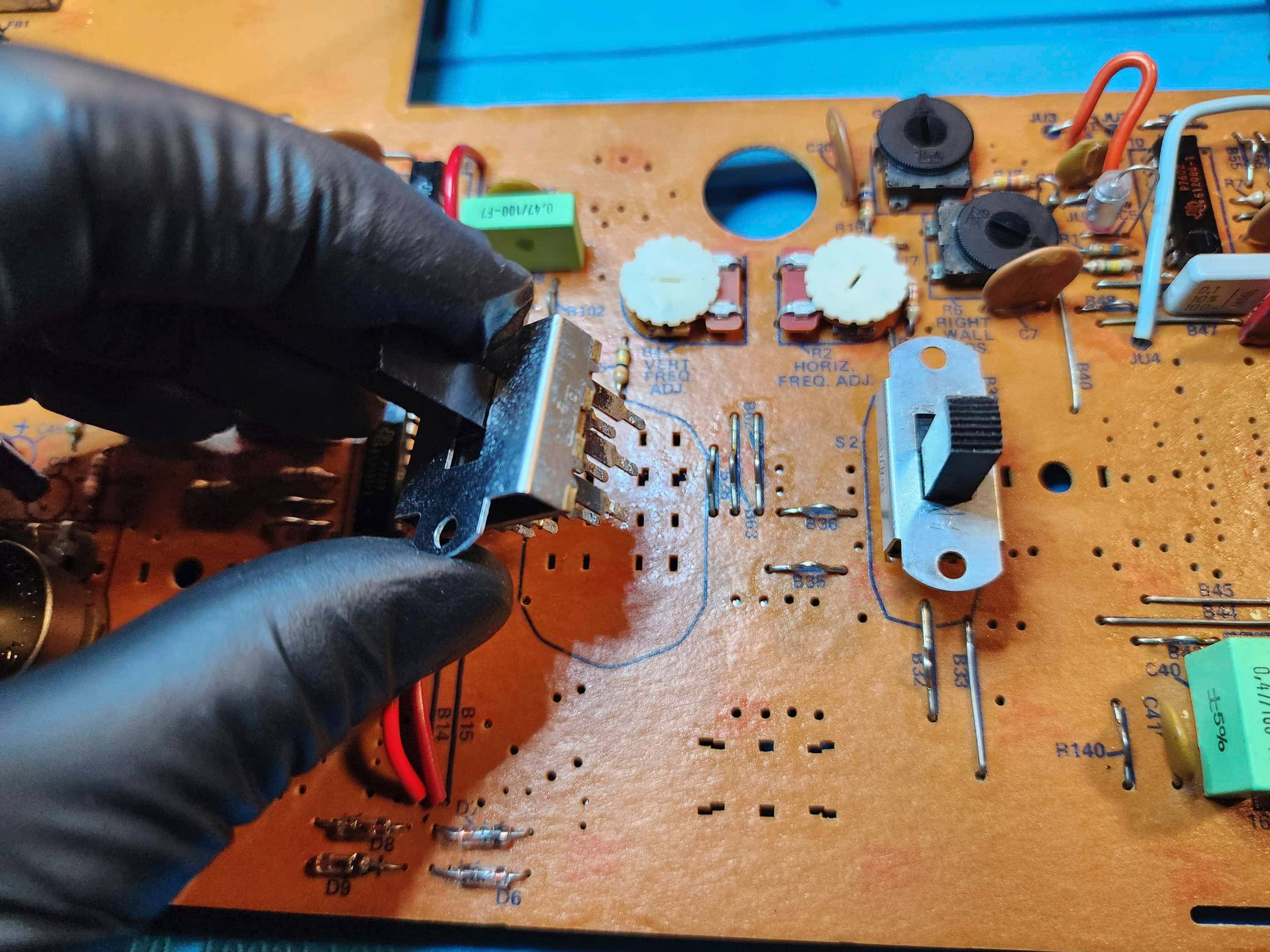
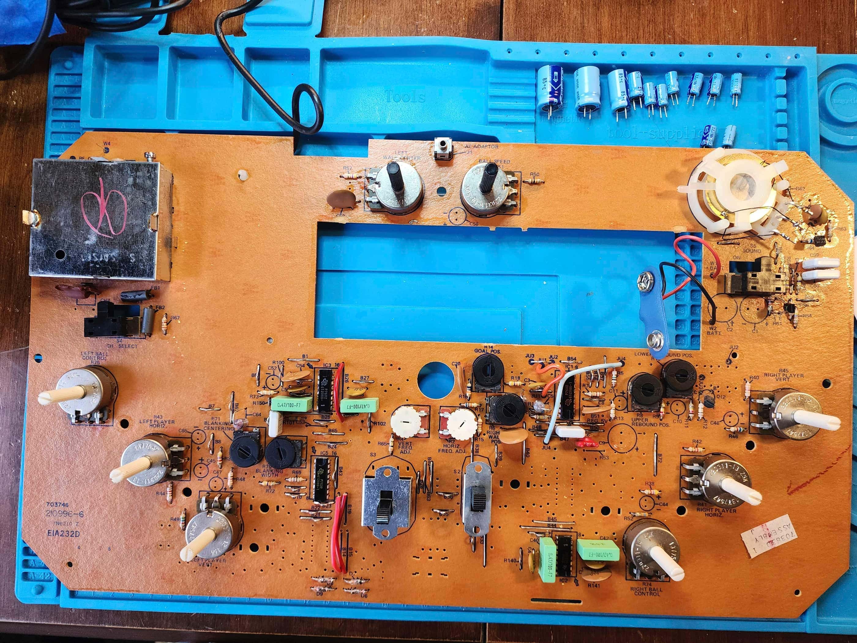
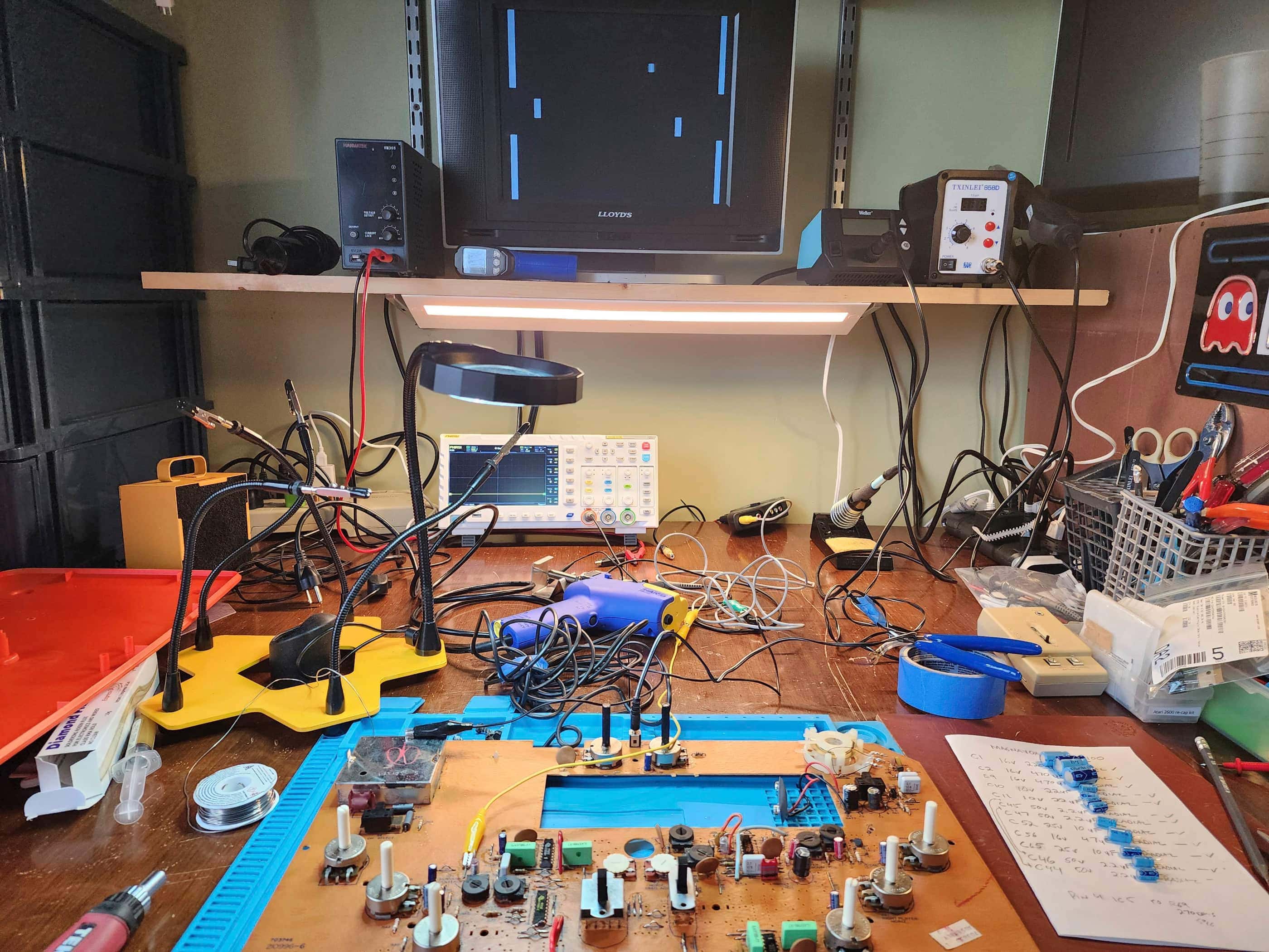
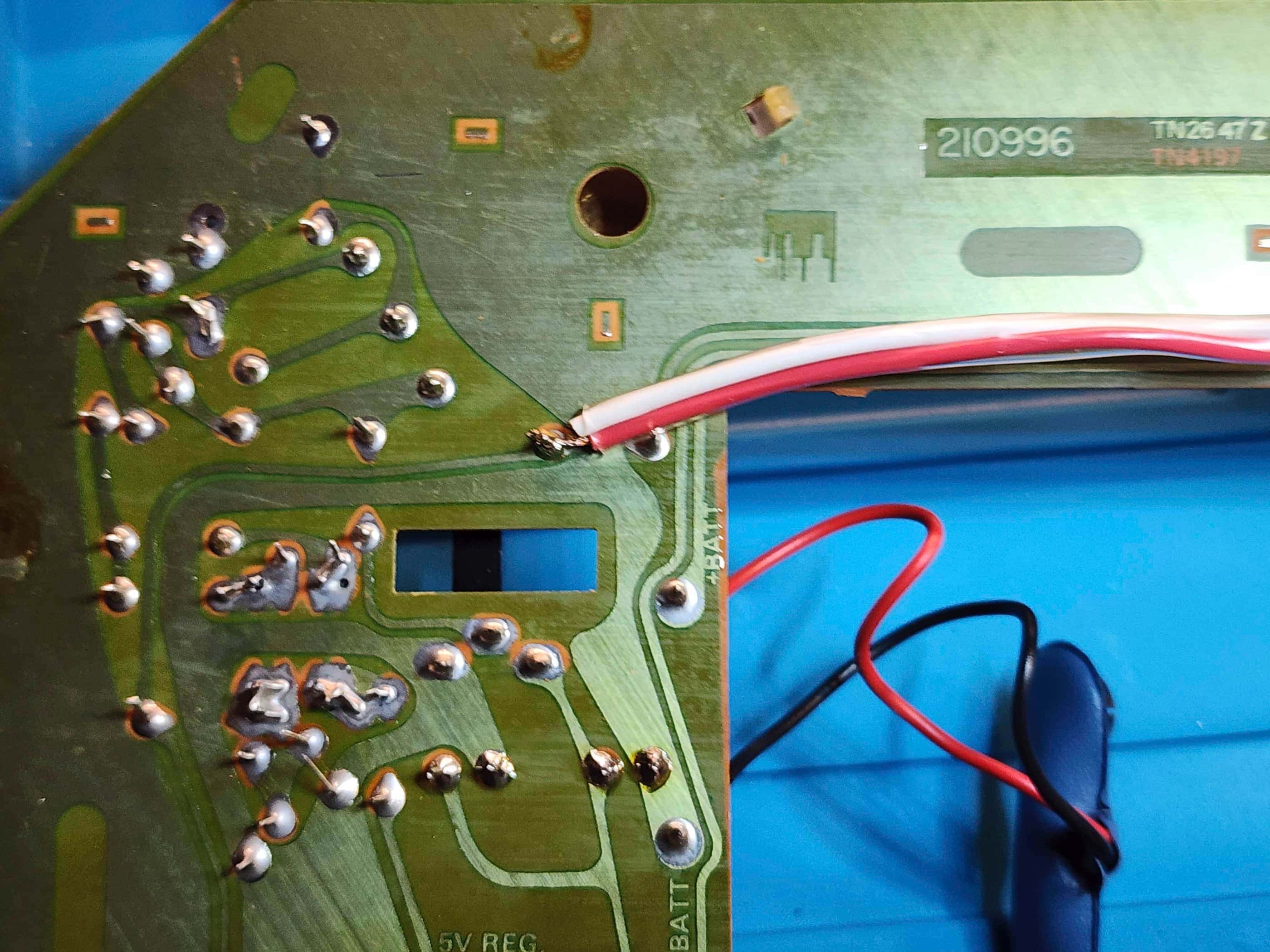
Project Details: This gem came in its original box (no styrofoam) but was DOA. After exhausting some obvious reasons as to why it wasn’t functioning, I suspected that it might be the power switch. I then desoldered and disassembled the switch, cleaned the dirty contacts, applied dielectric grease, reassembled and soldered the switch back onto the board. I powered the unit on and… nothing. 🤔 I proceeded to do continuity checks on the board’s traces even though a visual inspection showed no obvious flaws. This is when I discovered a significant loss of voltage along a trace. I soldered a wire hack to bypass the damaged section (yellow wire pictured above) and powered the system on using batteries and… it sprung to life! 😀 I then discovered the left paddle was not working properly because the graphics were skittish when I turned the controller. I desoldered and disassembled the potentiometers on both paddles, cleaned them, applied dielectric grease, reassembled and soldered them back onto the board. I also performed a detailed cleaning process on the entire unit. This resulted in responsive controls and a fully functioning system.
Parts & Products Used: 99% isopropyl alcohol; dielectric grease; Chemical Guys Natural Shine; 22 gauge wire

Coleco Telstar Combat!
Years (1977-1980)
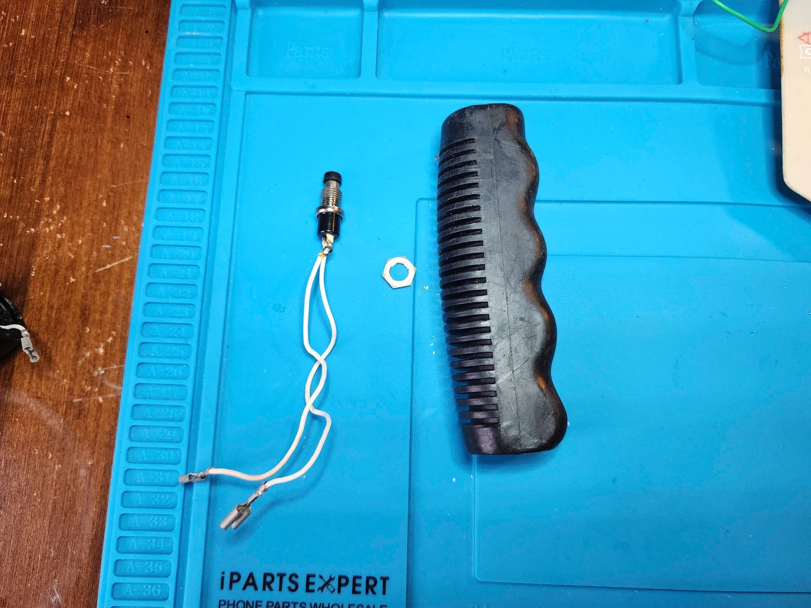
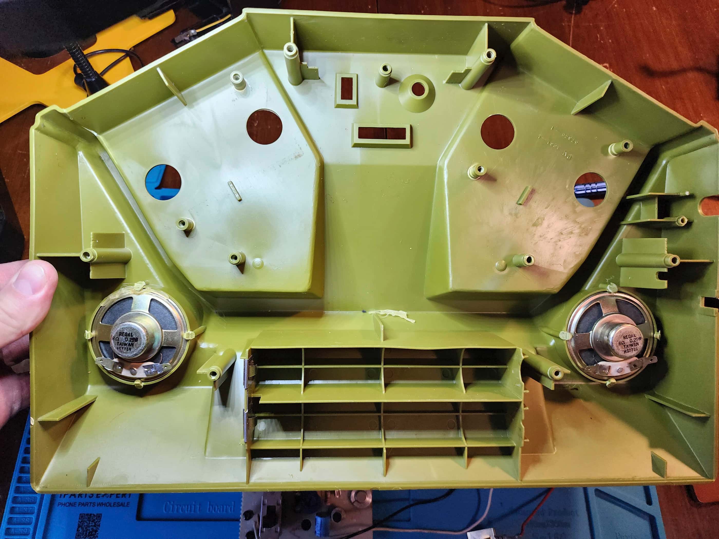
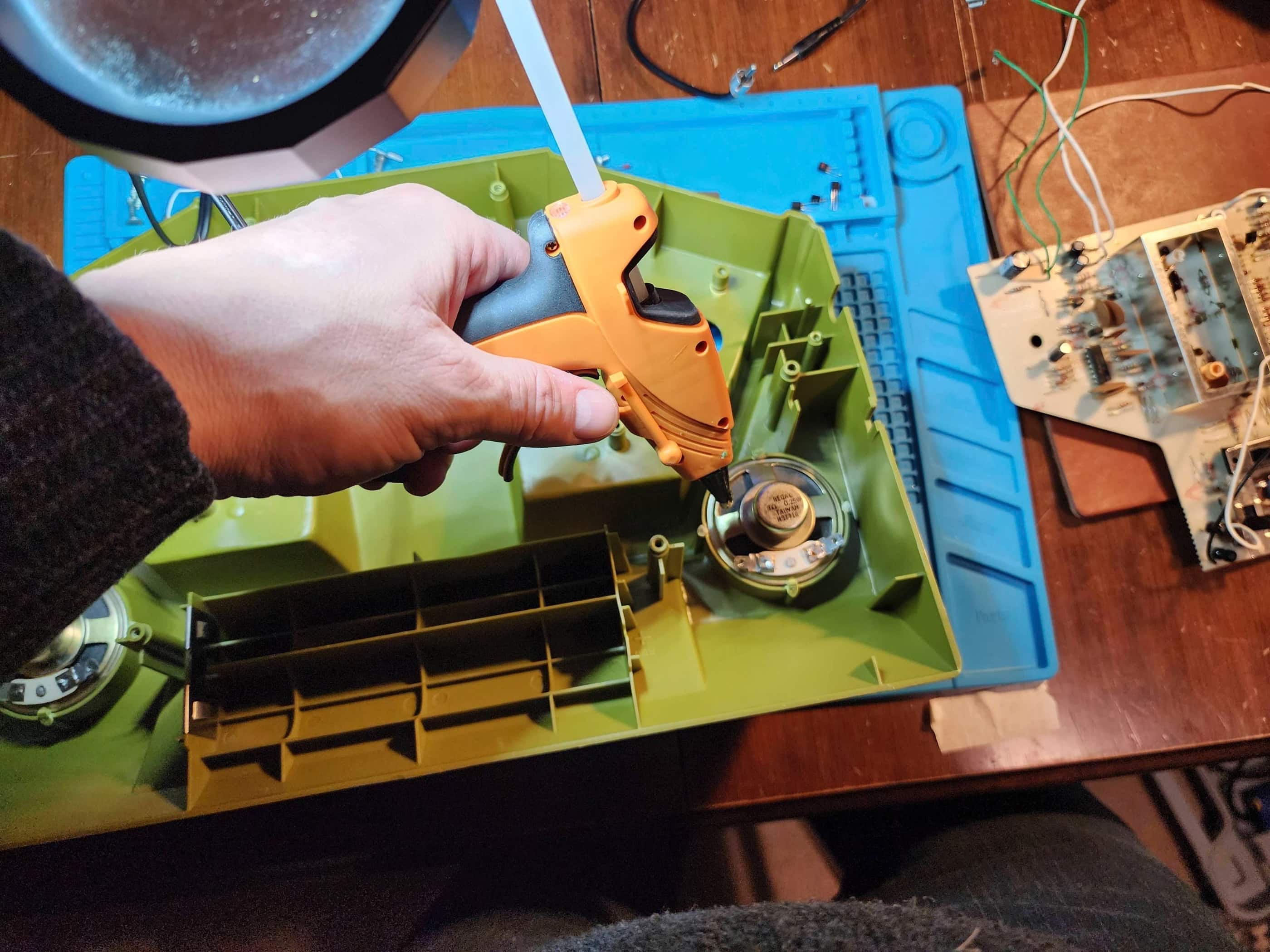
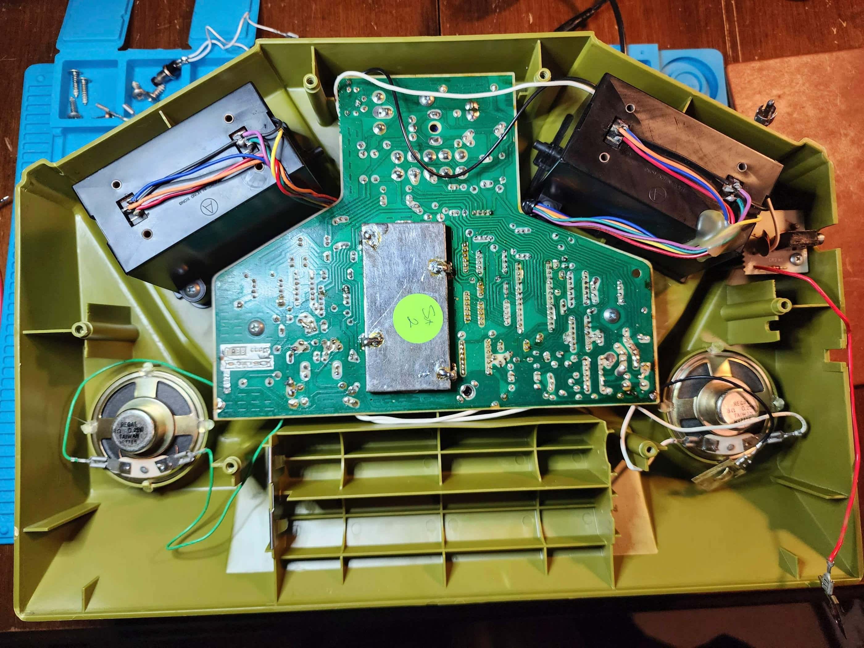
Interesting Fact: Combat! was unique among first generation consoles. While most other companies were focused entirely on Pong-type systems, Coleco decided to branch out and build a system that centred on tanks with dedicated tank-like controllers. While most Pong-type system used the AY-3-8500 chip, Combat! used the AY-3-8700 chip that featured 4 variations of a tank battle game. (source) It also included stereo sound, with one speaker dedicated to the sound of tank motors and one to firing and explosions.
Condition When Acquired: Partially Functional – video and audio issues
Current Condition: Fully Functional


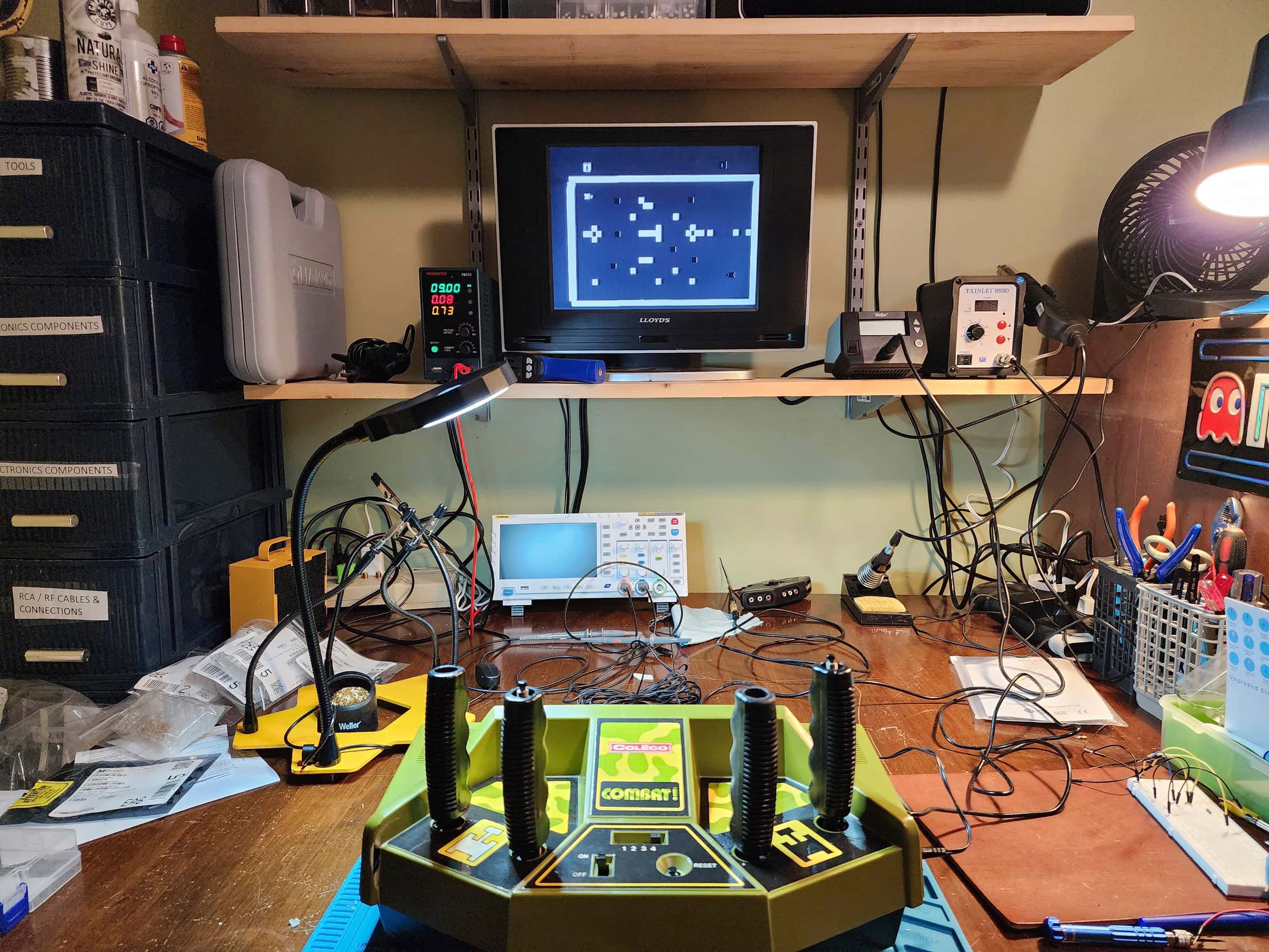
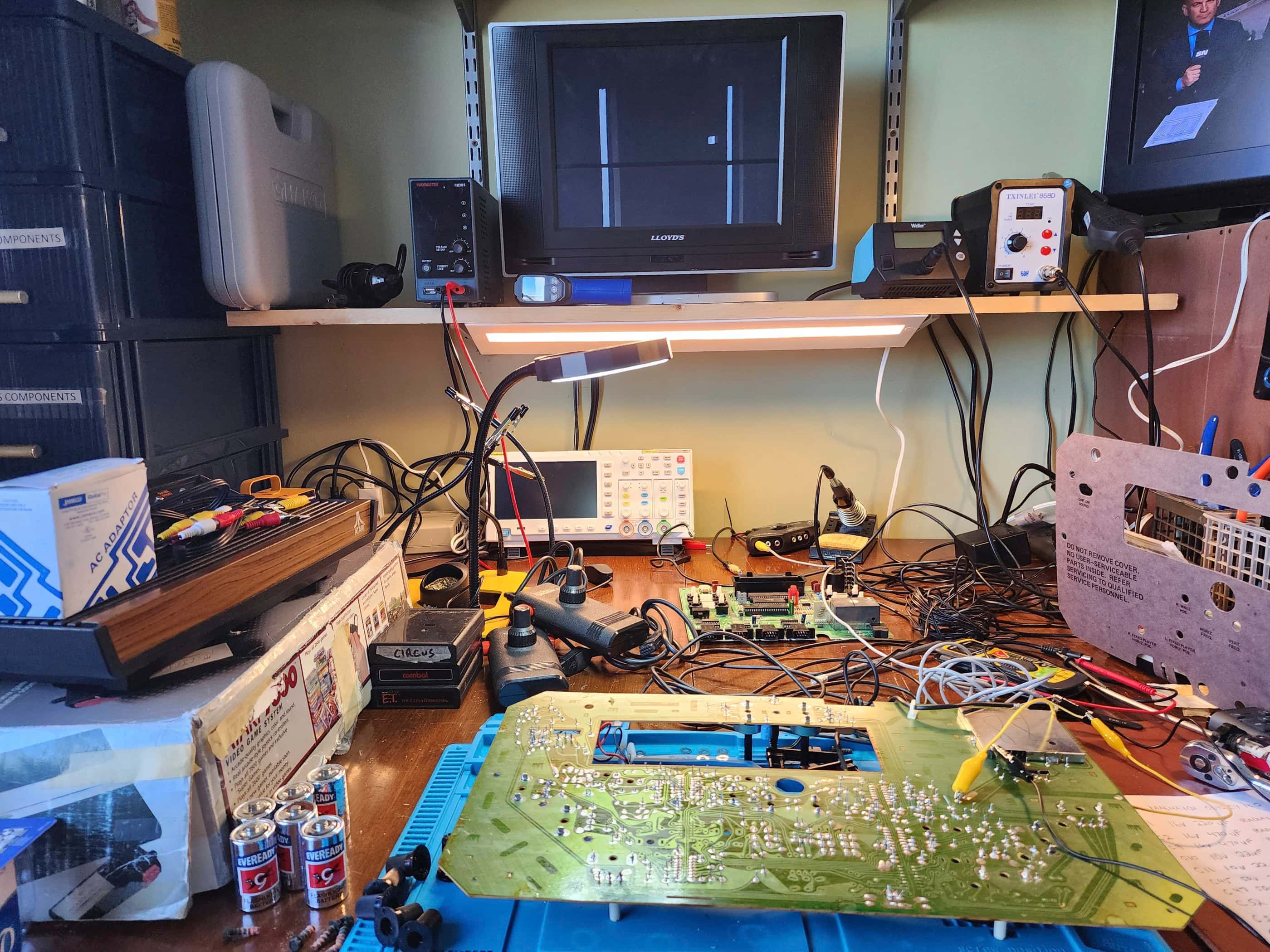
Project Details: I was super stoked to find this unit in the first place, and I had no idea if it worked or not. My initial concern was whether the built-in controllers were intact and then from there, if the system functional. As it did not come with a power adapter, I used 6 ‘C’ batteries for an initial test.
After turning it on and nothing happening, I was a little dismayed; however, I pushed the reset button and suddenly, I had sound and a game displayed. Nice! There was at least something to work with and I took note that once the unit was powered on, you had to push the reset button to get it to work.
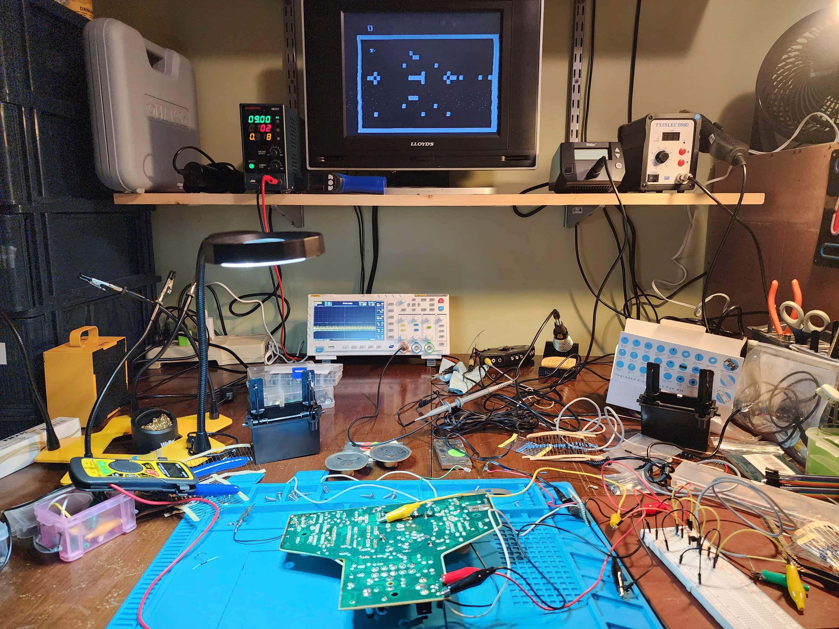
The big problem was the video. It flickered terribly which made the system unplayable and there was ghosting off the white obstacles in games 1 through 3. The good news was that I could see that all four controller sticks worked: moving the white tank and then the black tank. This is when I noticed that the sound for the tank motors cut in and out, which indicated another issue. Just in case it was the batteries causing this, I hooked the unit up to my benchtop supply and set it to the designated 9V 200 mAh, with the same result.
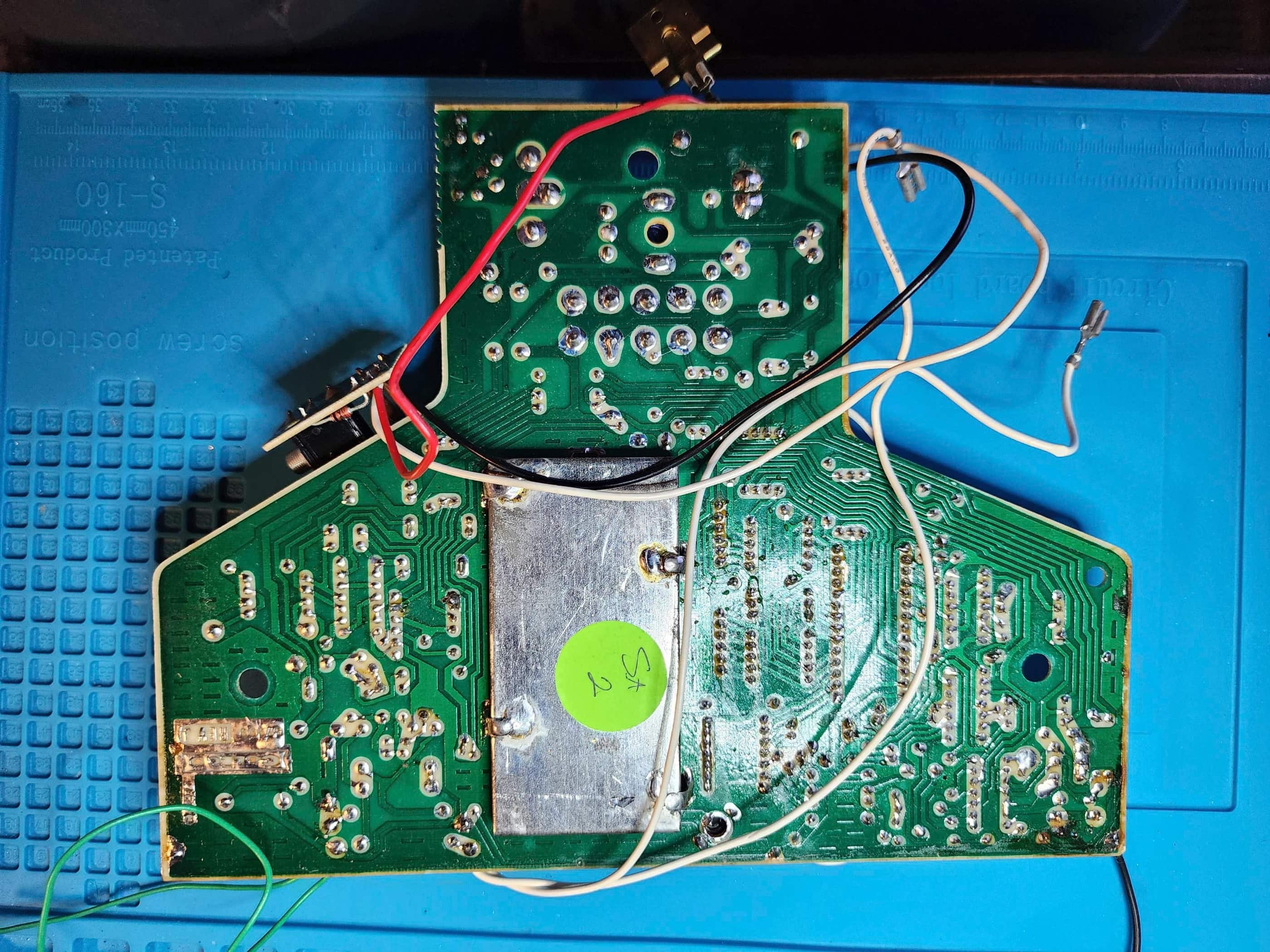
The relative rarity of Combat! meant there isn’t much information online, and so I leaned heavily on an Atari Age thread (source) related to building a composite mod – which was never concluded in the forum, but I’ll get to that later. I owe a HUGE THANKS to the contributors to this post, as this was the basis of all the information I had to go on, in particular, the Combat! schematic that ChildofCV created and shared on page 3. THANK YOU!! 🙂
To disassemble the console, I first used a hair dryer to heat up the rubber grips on the controllers. This worked like a charm and they came off without a hitch (I would also heat them up to put them back on). From there, it was fairly straightforward to take everything else apart.
Once I had the PCB removed, I then set about trying to fix the video. I was able to get a less terrible output by adjusting the orange channel tuner. However, the white tuner was useless as it no longer worked. However, the orange tuner adjustment meant that the video still pulsated badly, but it was a bit better than before.
This is when I began to focus on cleaning the power switch and the game switch to make sure there weren’t any power / contact issues affecting the video. I also checked the voltages on the 8700 and all the other ICs but everything seemed in spec. I then de-soldered, cleaned, and reassembled both the power switch and the game select switch and soldered them back onto the board.
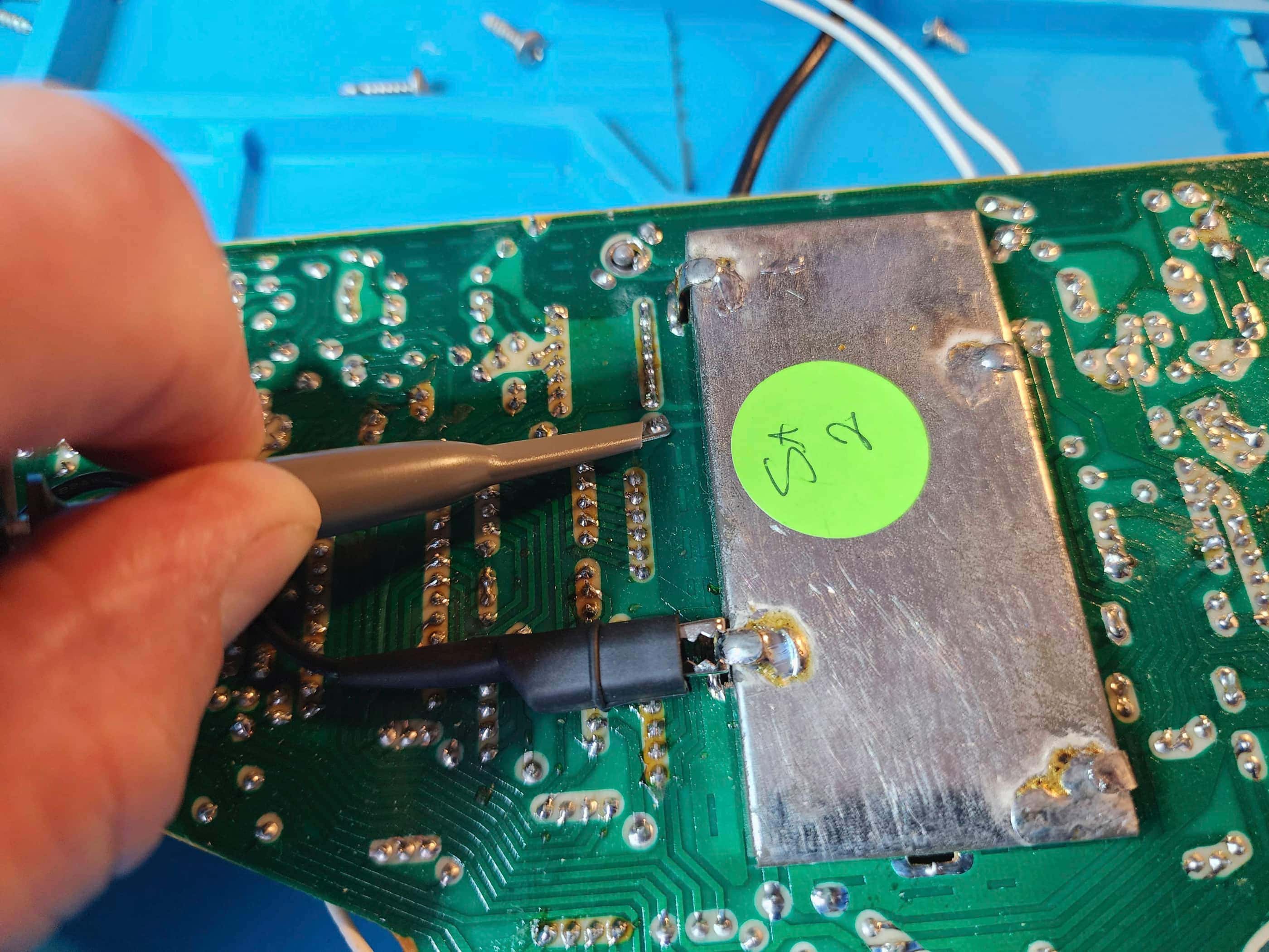
Unfortunately, none of this really helped and so I began to explore a composite mod. Following the discussion on the Atari Age thread, I set about trying to emulate some of the theoretical and prototype mods on a breadboard. The only one that I could get to work was the one that was demonstrated using the 100 ohm and 470 ohm voltage divider. Like the poster, I had a clear enough output, but the background was too dark. If I turned up the brightness all the way, it looked normal and coupled with this, the ghosting had also disappeared. For reference, the voltage at the signal choke point between L1 and the start of the RF modulator was a largely consistent 1.36 VDC with the VPP fluctuating between 750 mV and 1.6 V.
I experimented with different components including a video op amp as proposed in the forum along with different configurations and values. I also tried different emitter follower configurations with a Darlington transistor and I was unable to match the output of the first comp mod. This does not mean that there isn’t a better or more optimal composite mod, it merely means I’m out of my depth at the moment and that I need to do more learning.
At this point I decided to re-cap the board, again, just in case a faulty cap was to blame. Unfortunately, this didn’t improve anything. My final video adjustment (for now, because I can’t stop thinking about this), was to adjust the variable transformer LT4 because in my quest for a composite mod, I had noticed that the frequency from the 8700 clock pin (19) was all over the place. I used a small flathead screwdriver to turn LT4 slowly in a clockwise direction until I had a much more stabilized output on my TV. I then tested the 8700 sync pin (18) that was previously jumping between 87 to 94 Hz and I now had a very stable and consistent 60 Hz on pin 18 as well as a matching frequency on the 4011 chip IC3 and C16.
In fact, outside of the ghosting that I discovered would disappear when I touched my finger to the white tuner and then another finger to the RF shielding, I had a decent and stable RF output. As this was light year’s better than what it was before and close to what it should be, I decided to leave it for now… but as I said before, I can’t stop thinking about it and I know I will return in the near future to try and figure out a composite mod.
With the video mostly good, I then turned my attention to the hit and miss tank motor audio on the right speaker. I could tell that the 4013 chip IC2 was outputting an audio signal from pin 13, so my first thought was that it could be a loose wire, so I resoldered W3 & W4, but this didn’t help. As I had replaced the electrolytic capacitor C38, I thought it couldn’t be it, but on the off chance it was, I replaced it with another capacitor and still no dice. I then focused in on some of the other passive components and tested the resistors, ceramic capacitors, and the transistors. To be safe I replaced the Q3 & Q4 MPSA13 transistors, but this didn’t solve the problem.
I then began to re-focus on the 4013 IC2 chip. As I said, I could tell that it was outputting an audio signal but after testing everything including all the components and traces between it and the speaker, it was somehow not working. That’s when I decided to reflow the solder to the chip and suddenly, I had audio coming out of the speaker. Success!
After doing some final testing of the system on each of the four game modes, I cleaned the casing and control grips and put everything back together. I tested it again, and everything was working and displaying as it should.
However, I’m not done with this system. One day in the near future I think I’m going to open it up again and explore perfecting a comp mod – unless someone else posts the perfected version on Atari Age and then I can use that. 🙂 I think I’m also going to replace the 4011s and 4013 ICs, but for now, this rare but classic system is very playable and is an awesome addition to my collection.
Parts & Products Used: 99% isopropyl alcohol; Chemical Guys Natural Shine; electrolytic capacitors (radial) – 16v 470μF (1); 16v 100μF (1); 16v 33μF (2); 25v 4.7μF (1); 50v 1μF (1); MPSA13 transistors (2); dielectric grease

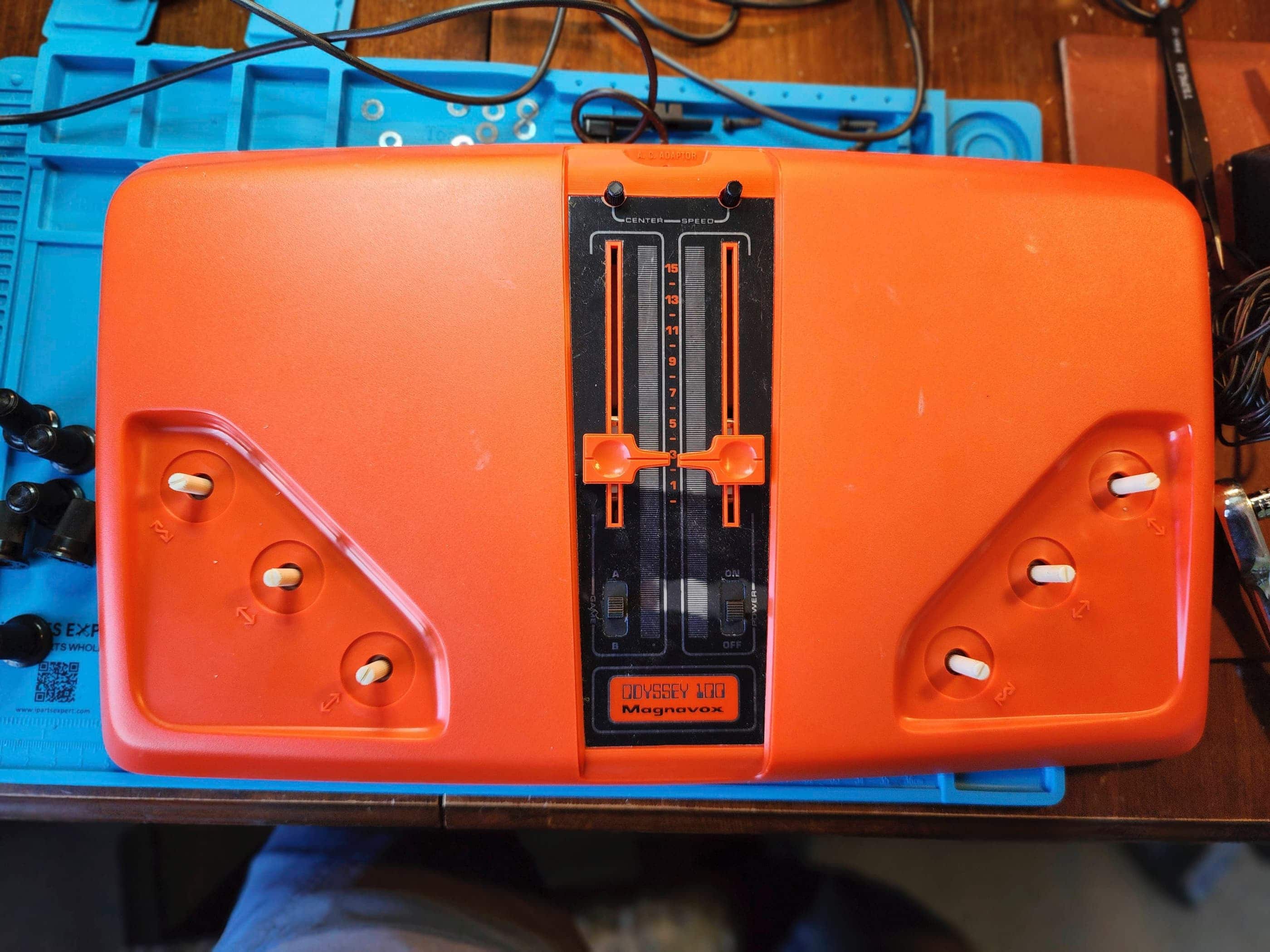
Magnavox Odyssey 100
Years (1975-1976)
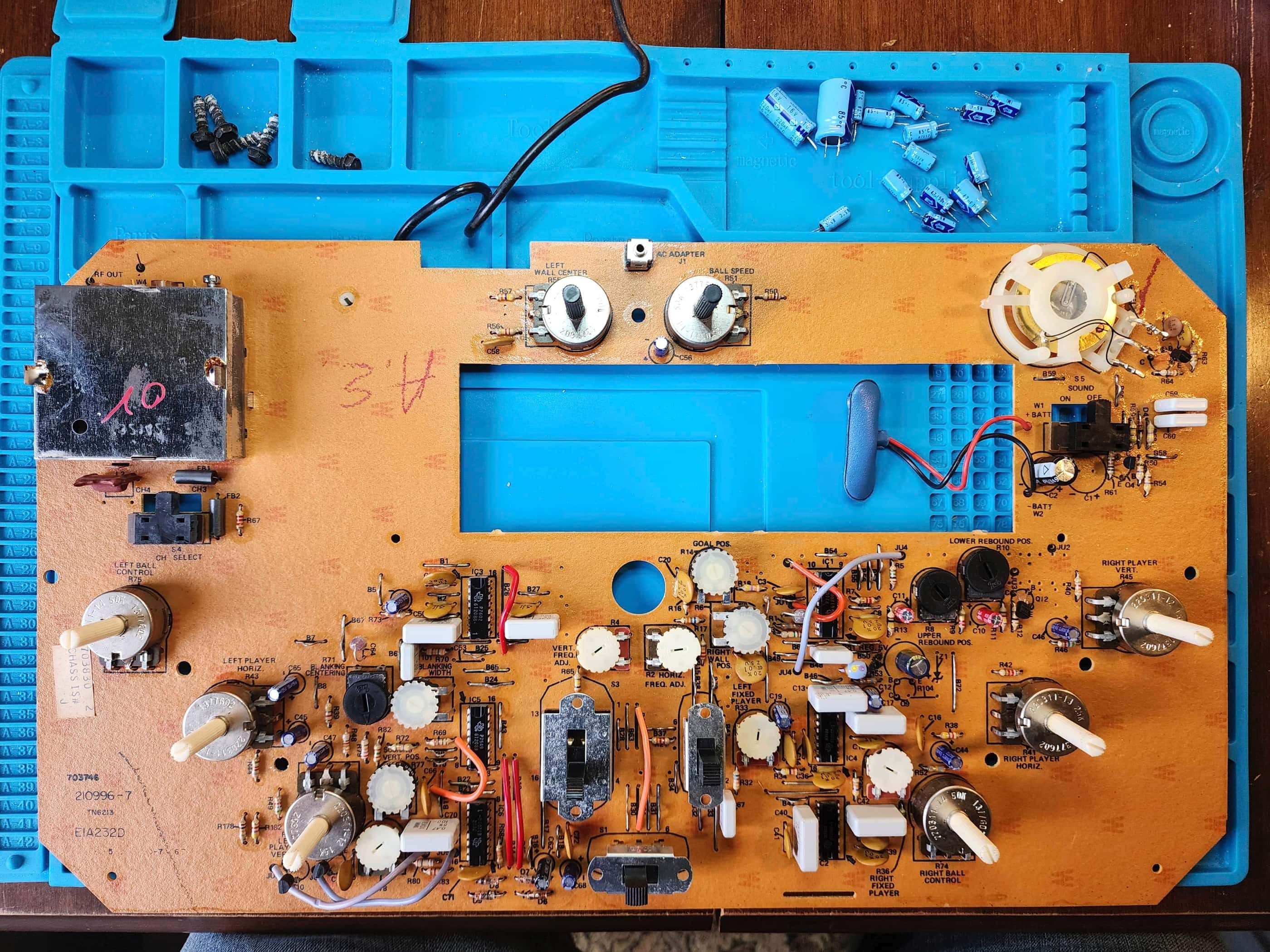
Interesting Fact: When Magnavox released the original Odyssey in 1972, it started the video game industry. (source) However, it wasn’t until 1975 that Magnavox produced a follow-up system: the Odyssey 100 along with the more deluxe, Odyssey 200. Launched in the spring of 1975, the Odyssey 100 and 200 did not use a single chip for its games. Instead, the 100 used 4 Texas Instrument chips to generate hockey and tennis, while the 200 used 6 chips for hockey, tennis, and ‘Smash’ (handball). (source) The reason for multiple chips was that Magnavox was worried that Texas Instruments wouldn’t have a single chip ready for delivery. (source) Hence, both the 100 and 200 use a simple, analog logic system. The three potentiometers on each side allow the players to move their paddles vertically, horizontally, and apply ‘English’ (warp the trajectory) after hitting the ball. Personally, I really like the ability to move the paddles horizontally and apply ‘English’ because this separates these systems from Pong or Super Pong; making the games more fun to play.
Condition When Acquired: Non-Functional
Current Condition: Fully Functional

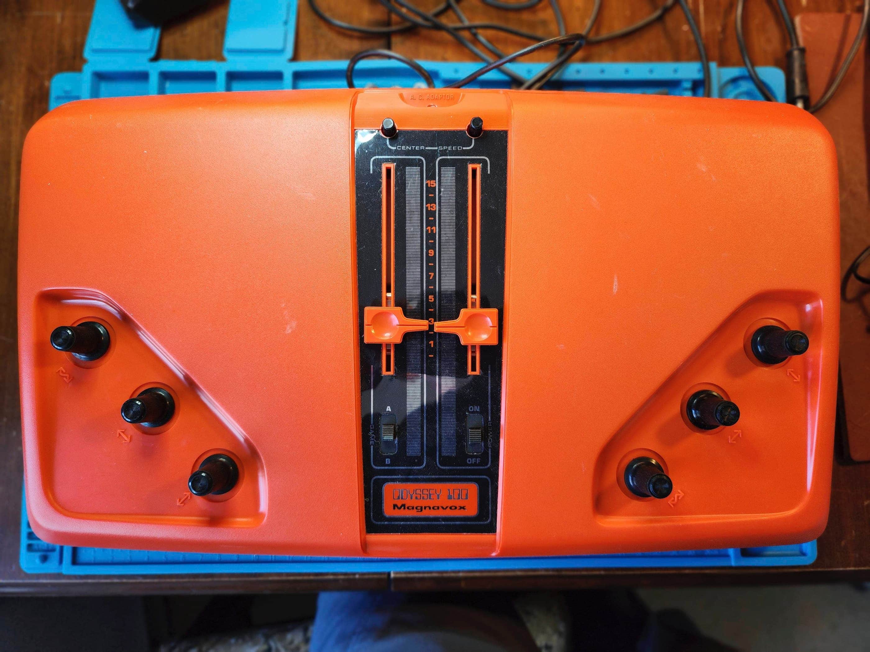


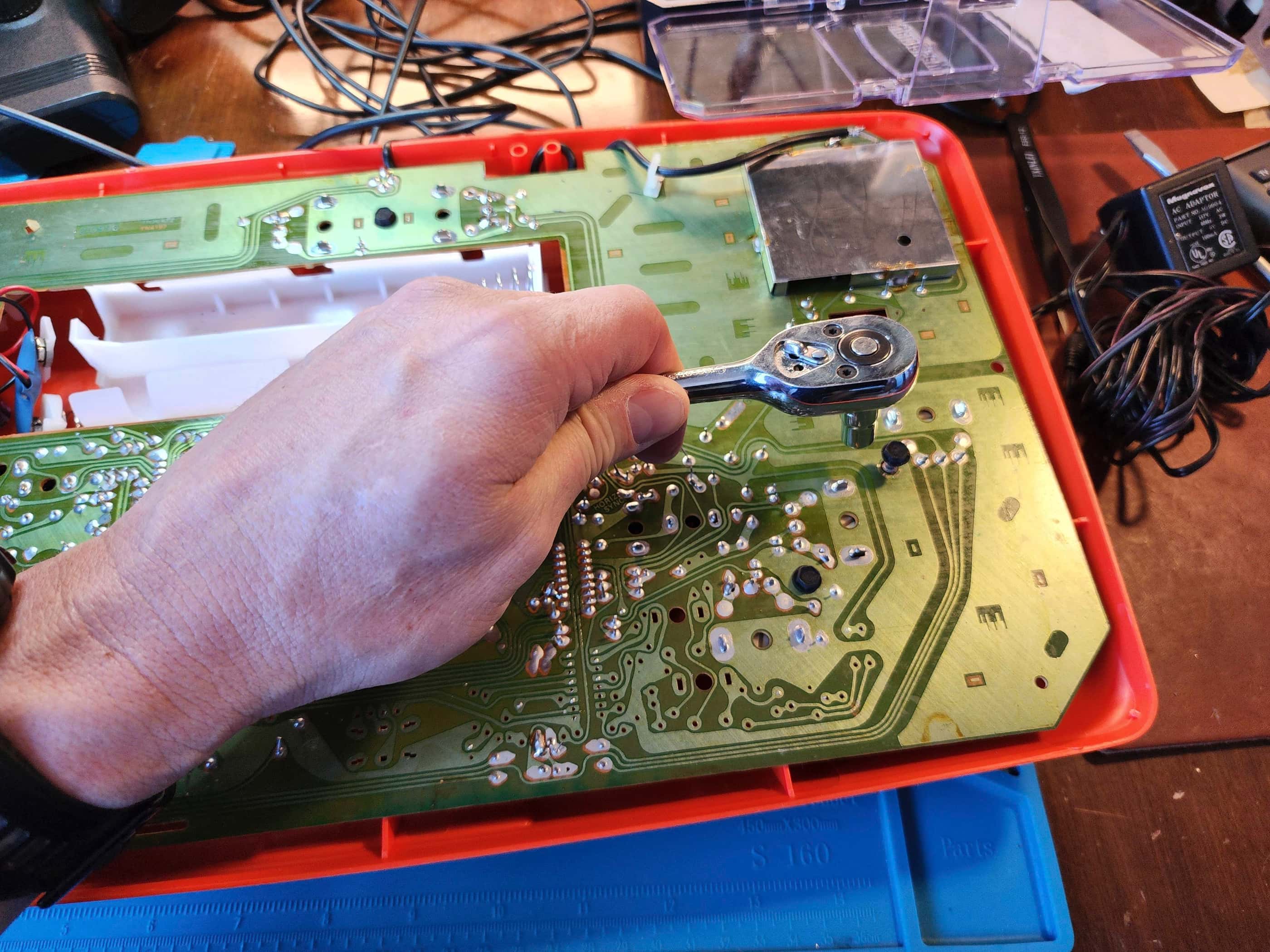


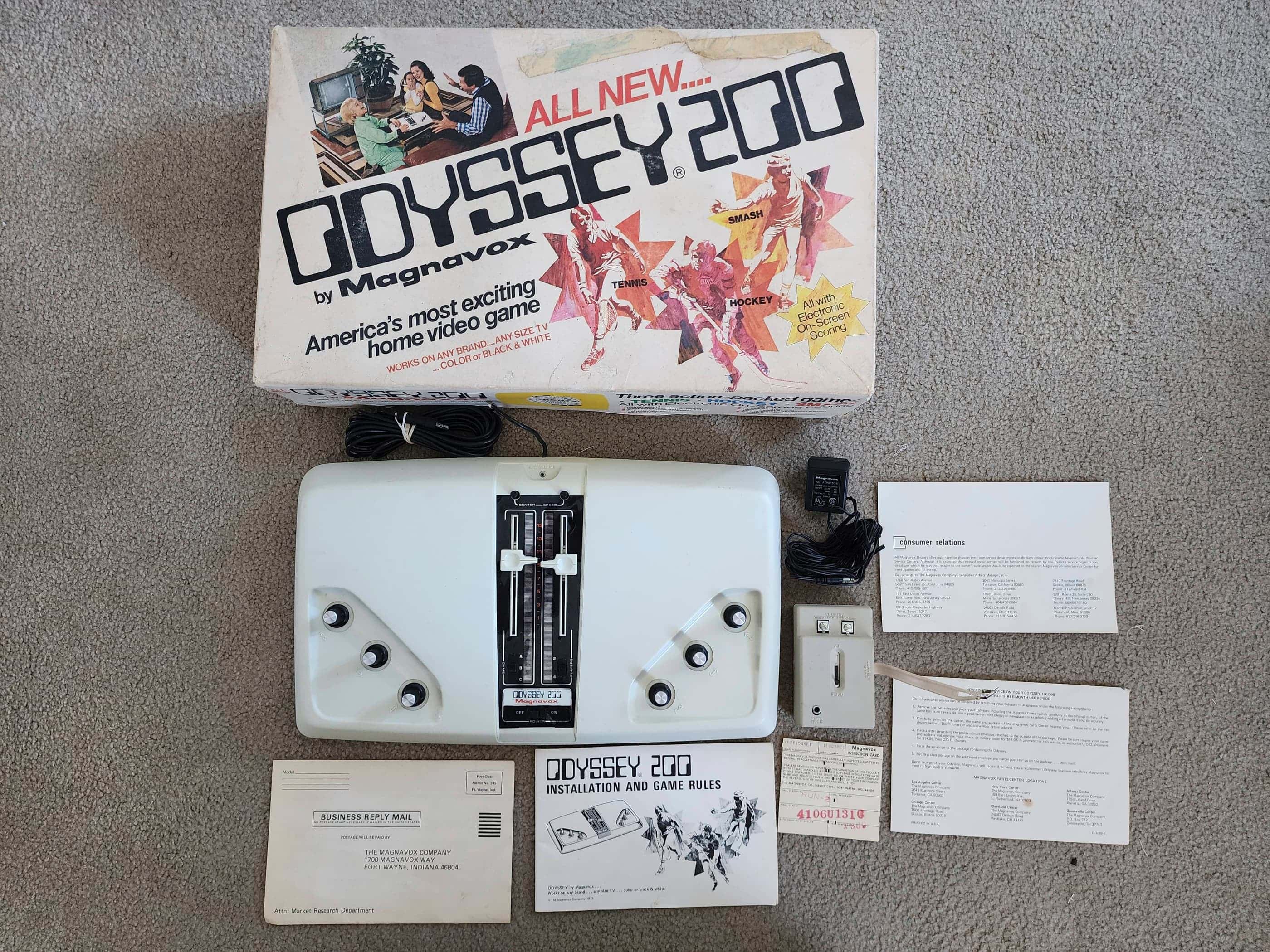
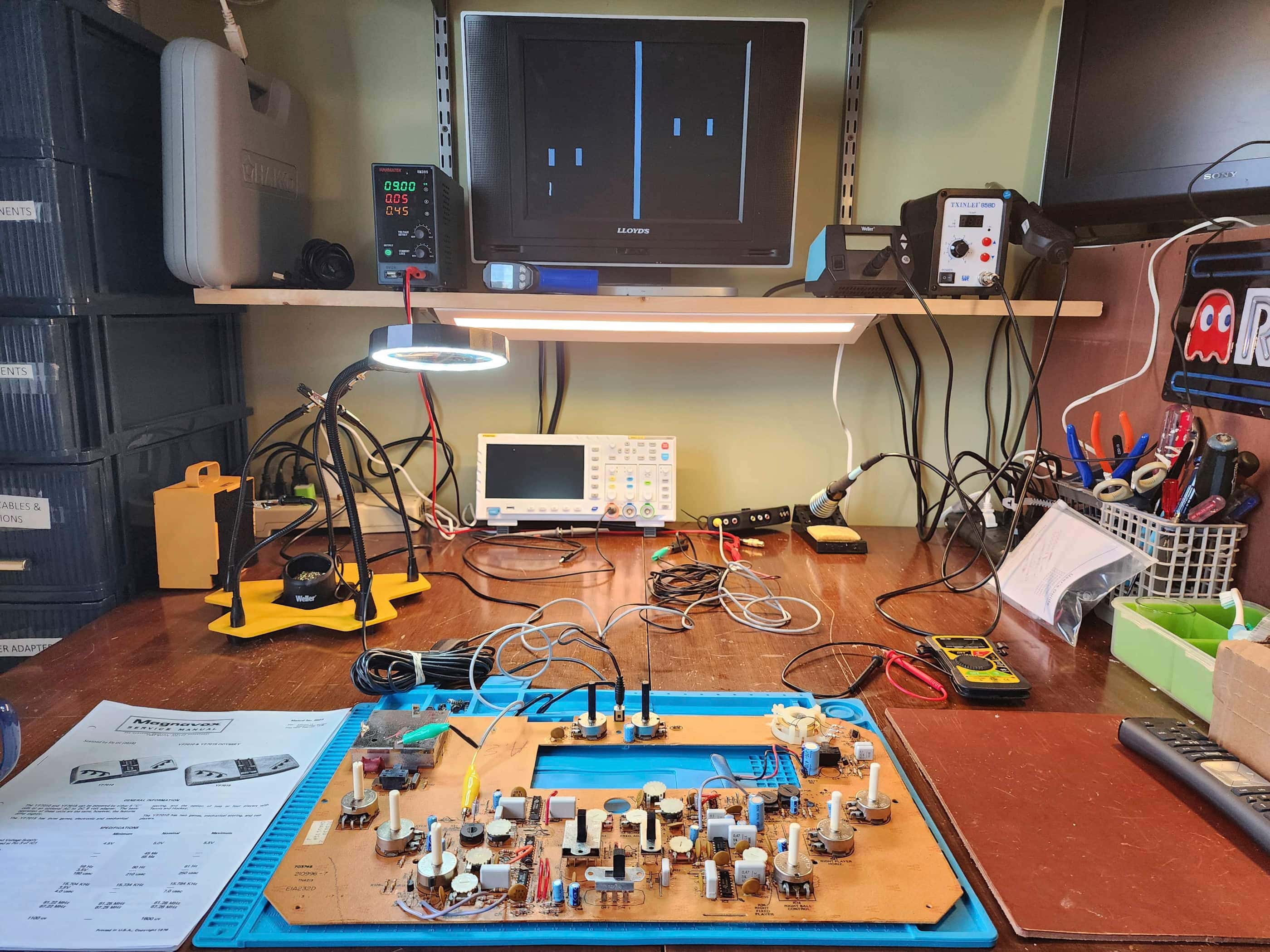
Project Details: When I saw this pop up on Ebay with the original box and manuals, I couldn’t resist. That it came from the east coast of the US, meant that it would take a few weeks for delivery, so I was excited when it finally arrived. As it was untested, I had no idea if it would work and since I’d never seen one before, I had no idea what I was getting into.
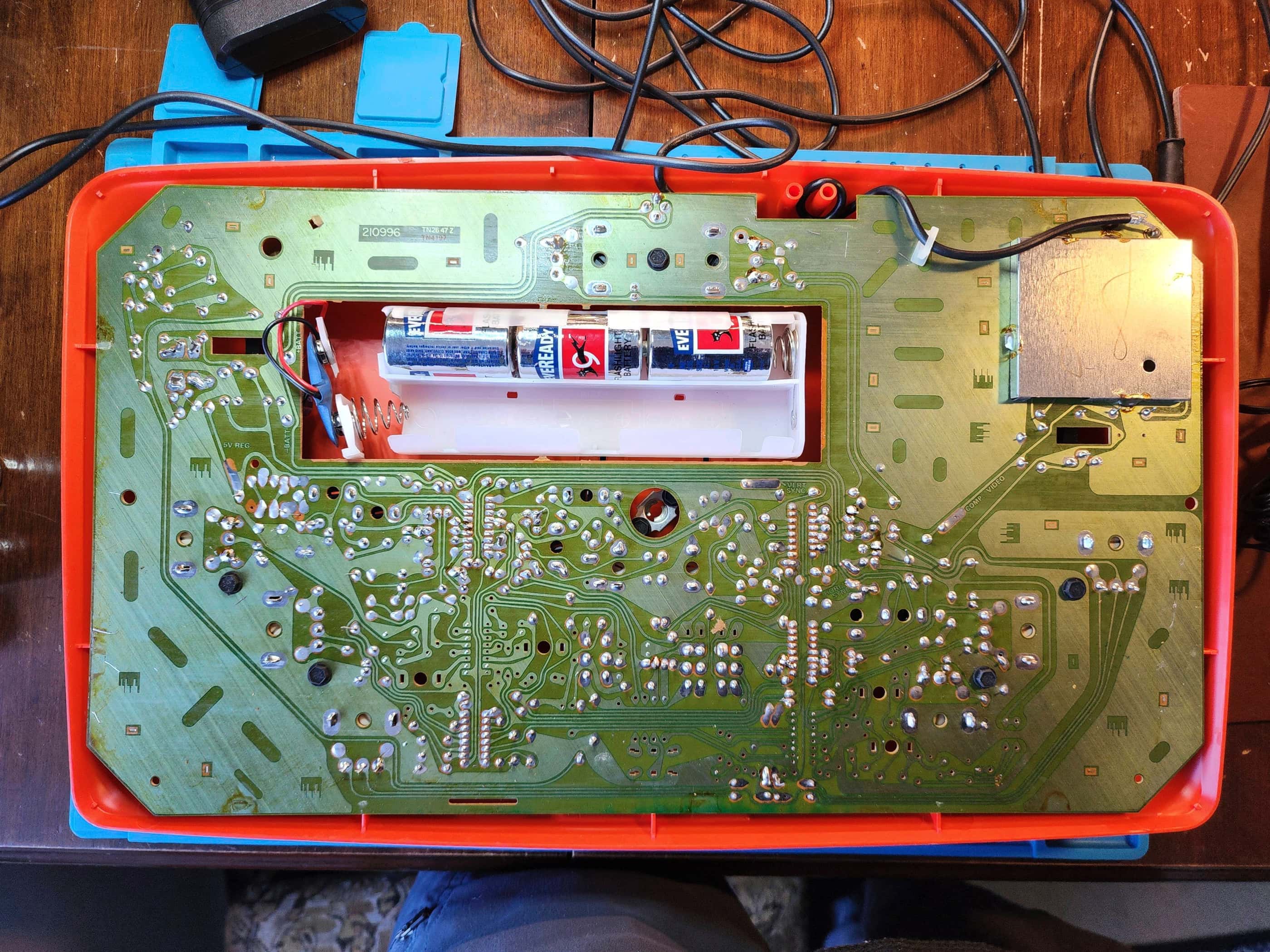
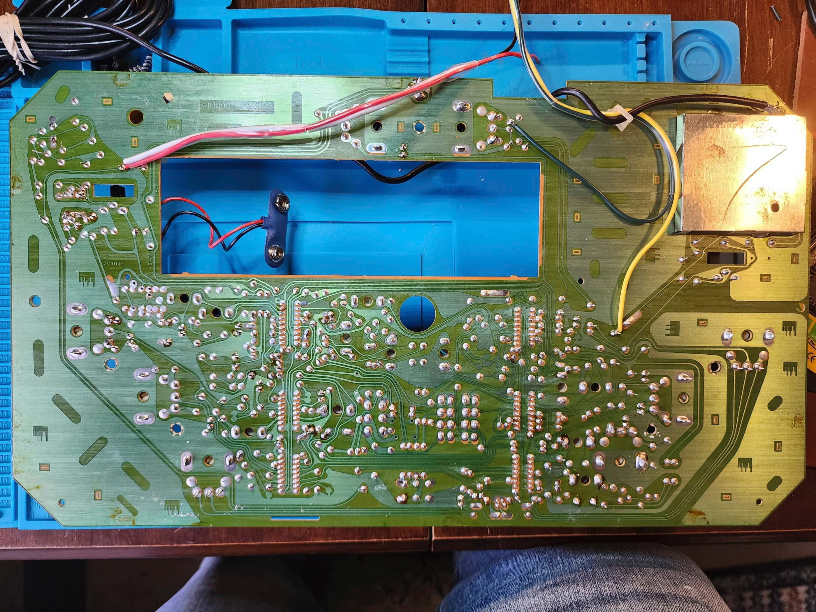
The first thing that I noticed was its proprietary RF cable and TV switchbox. This was identical to the cable that came with my Odyssey 2 and since it was simple to swap that out, I figured it would be the same for the 100. Nope. 😳 The RF cable is stripped and soldered onto the board and while replacing it was far from impossible, I discovered from Sly DC that it was even simpler to tap into the system’s composite signal. (source) This then is what I used for testing and what I would permaanently add to the system.
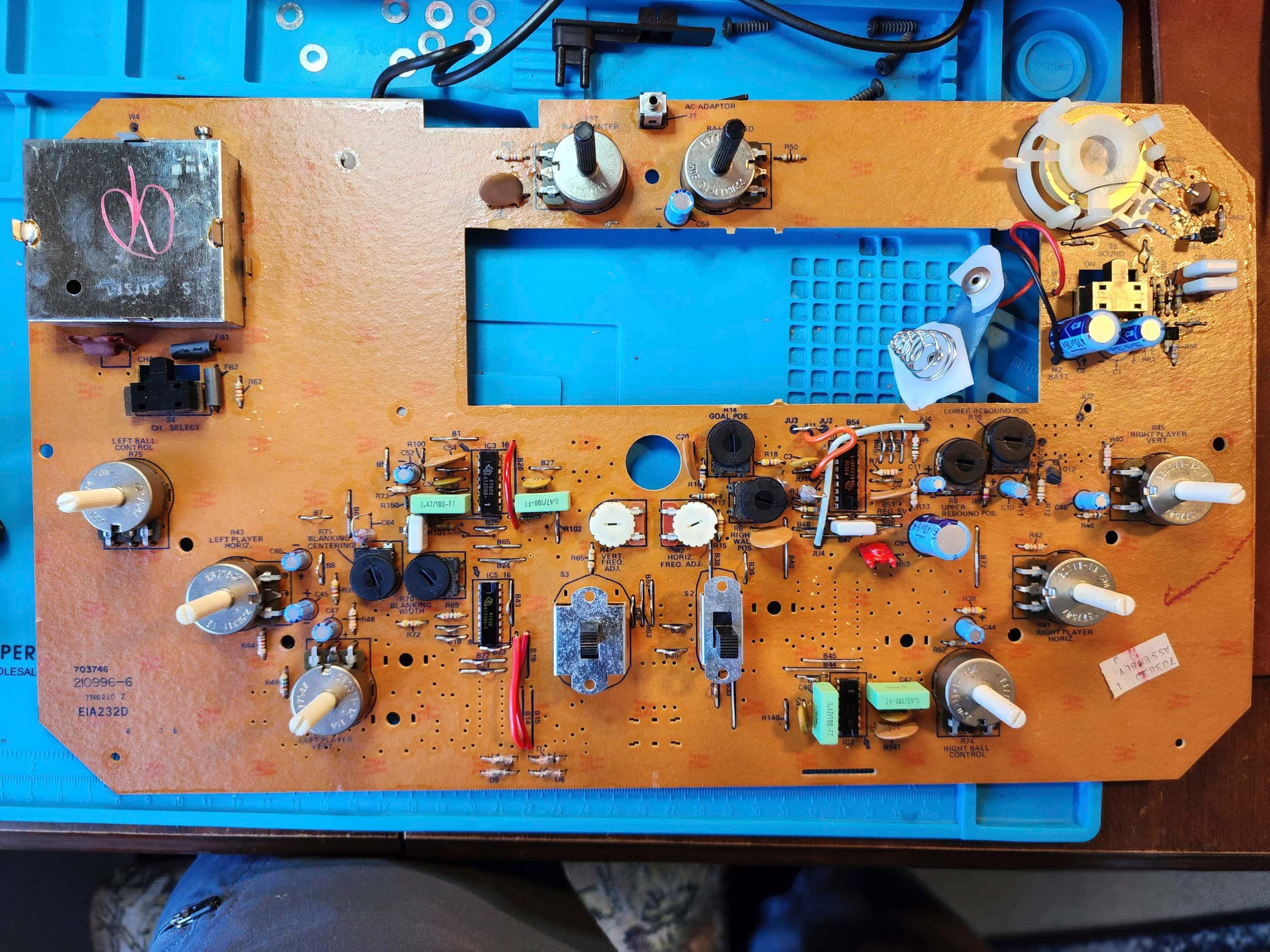
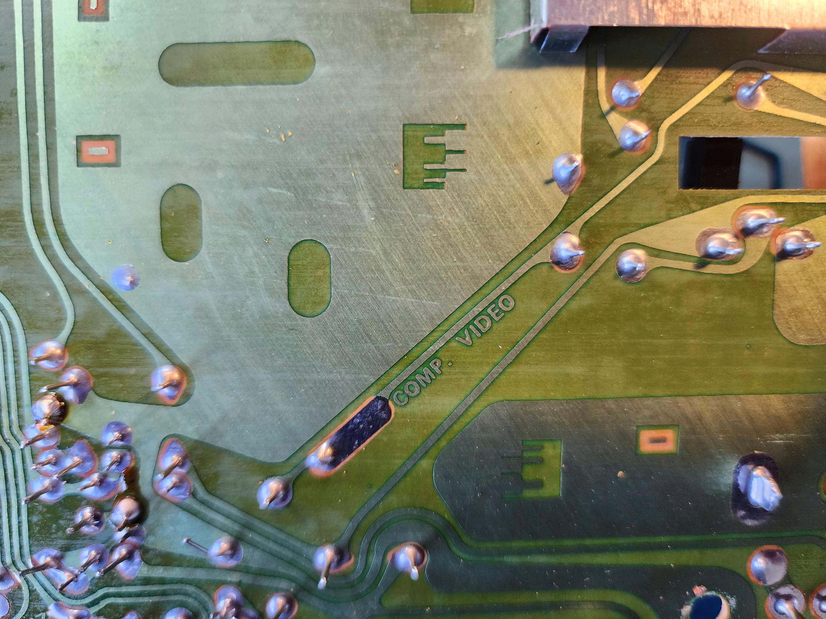
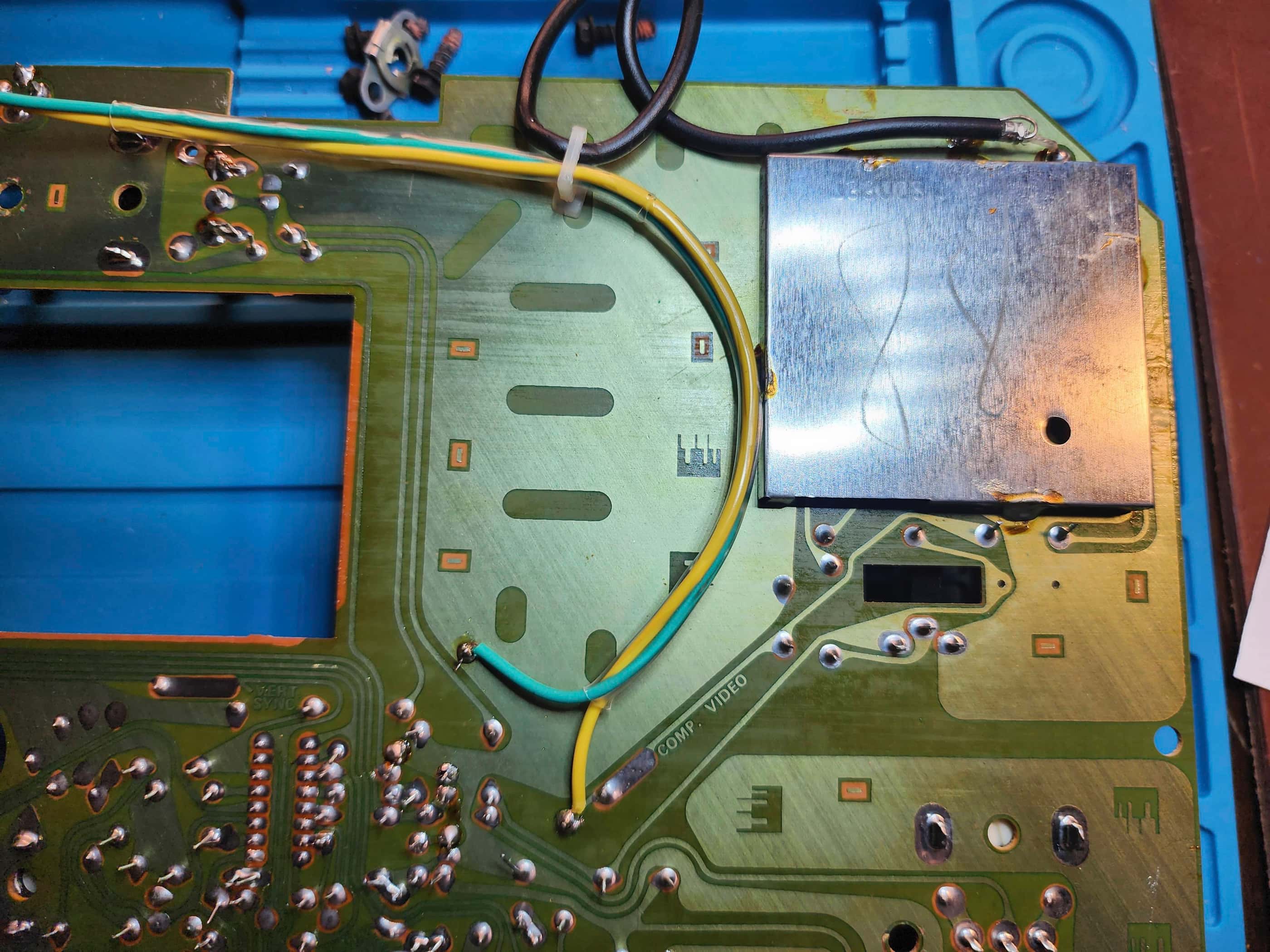
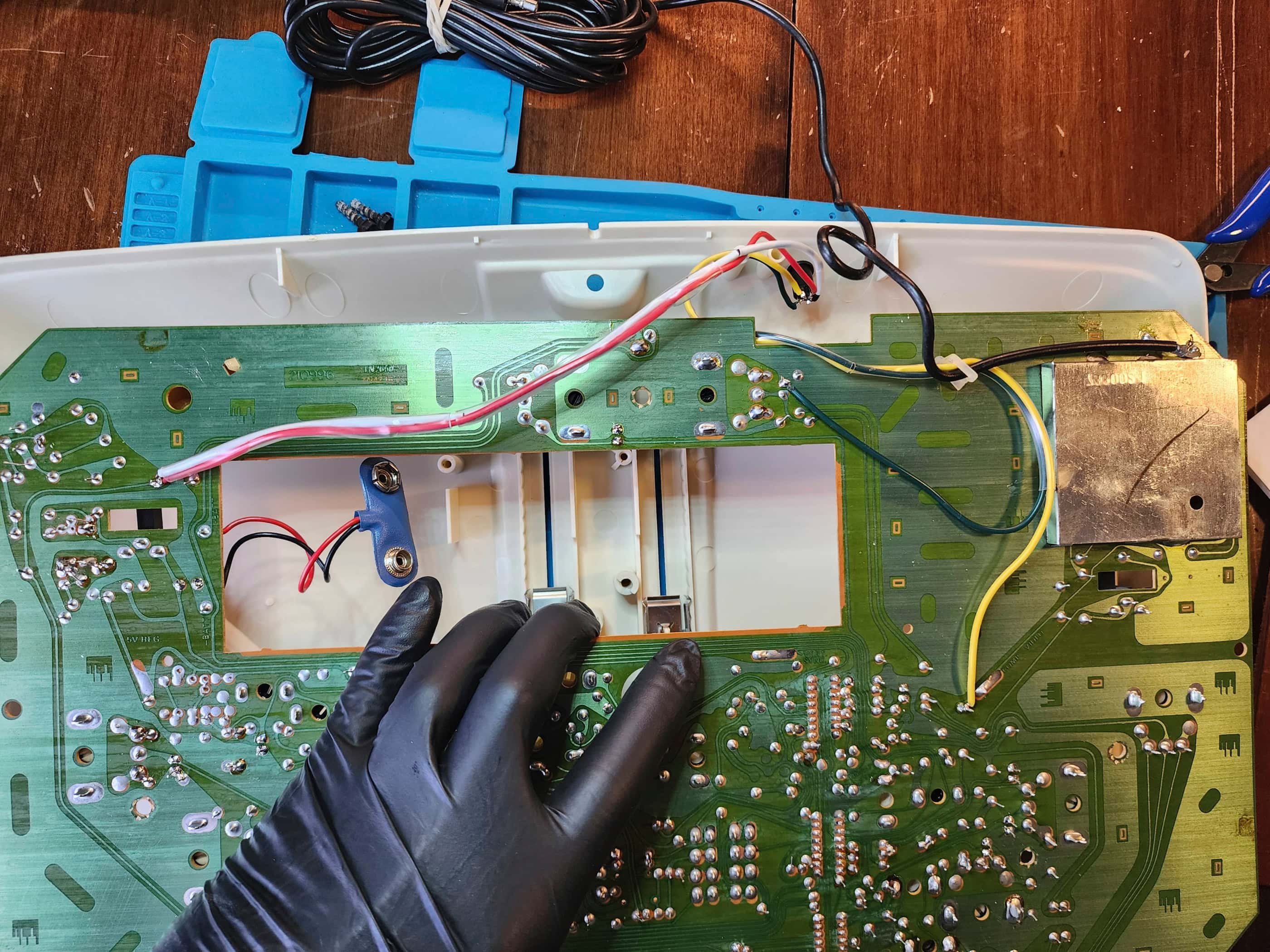
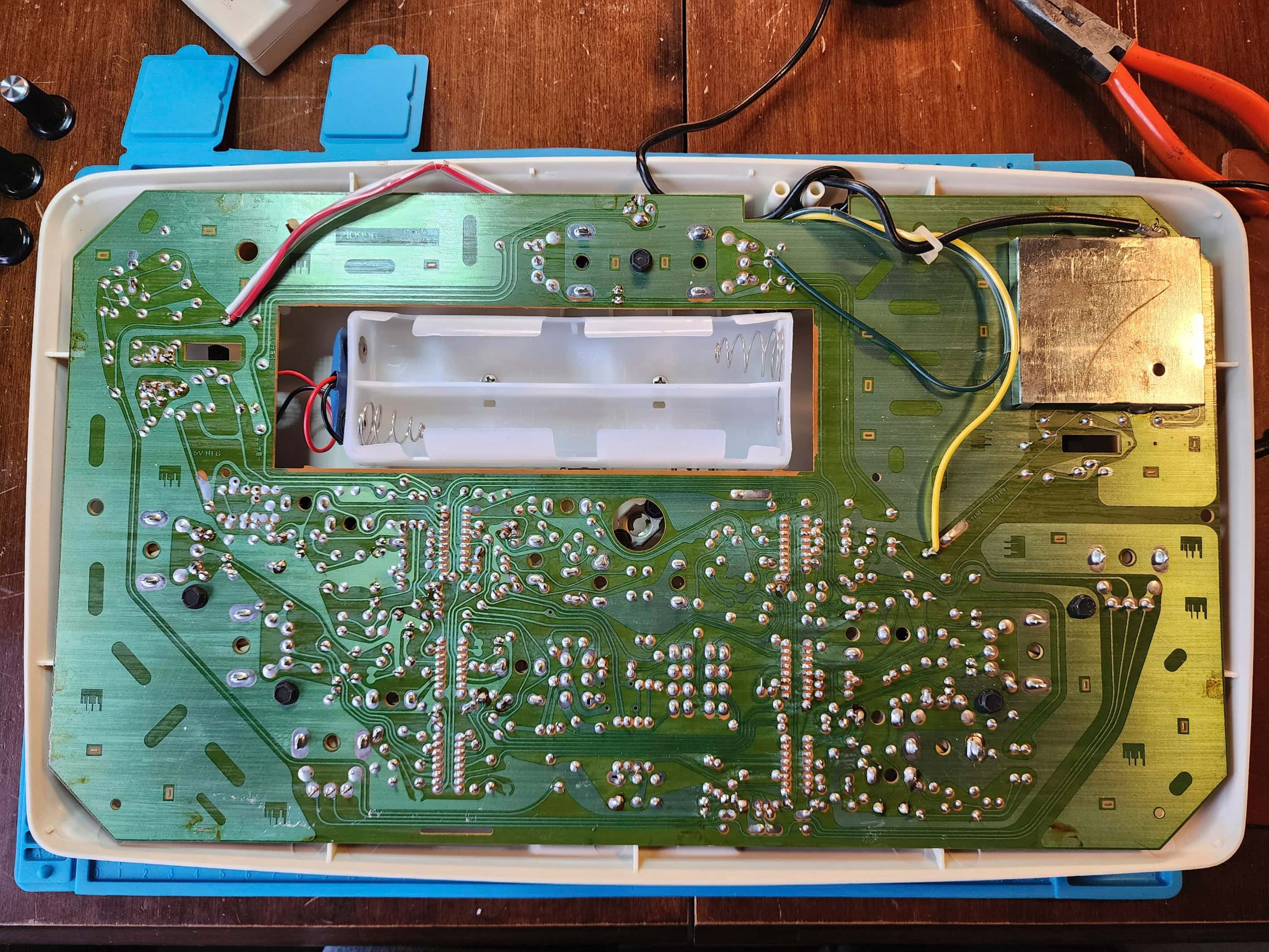
However, before I could even test the system, I noticed that its plastic battery compartment was broken, coupled with a badly corroded battery terminal. I then setup the composite mod by connecting the video out to the underside of B67 (then later to the top to make things easier) and the ground to the RF shielding on the modulator. The board also has ‘Comp. Video’ printed onto it, so it is super easy to find where you should connect. That you can run it directly from the board to the TV without any modifications is awesome, making this one of the easiest video mods out there. 😁
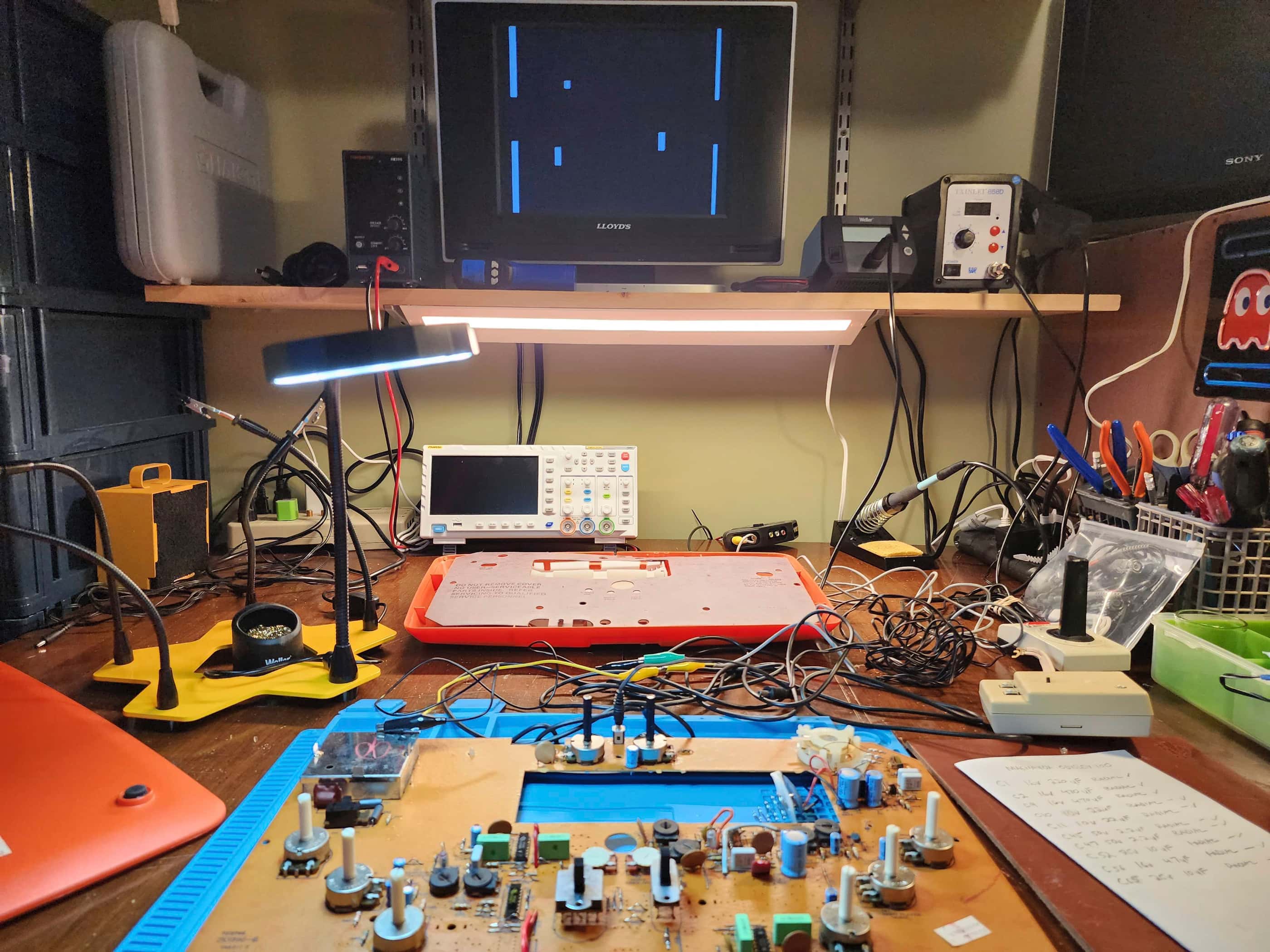
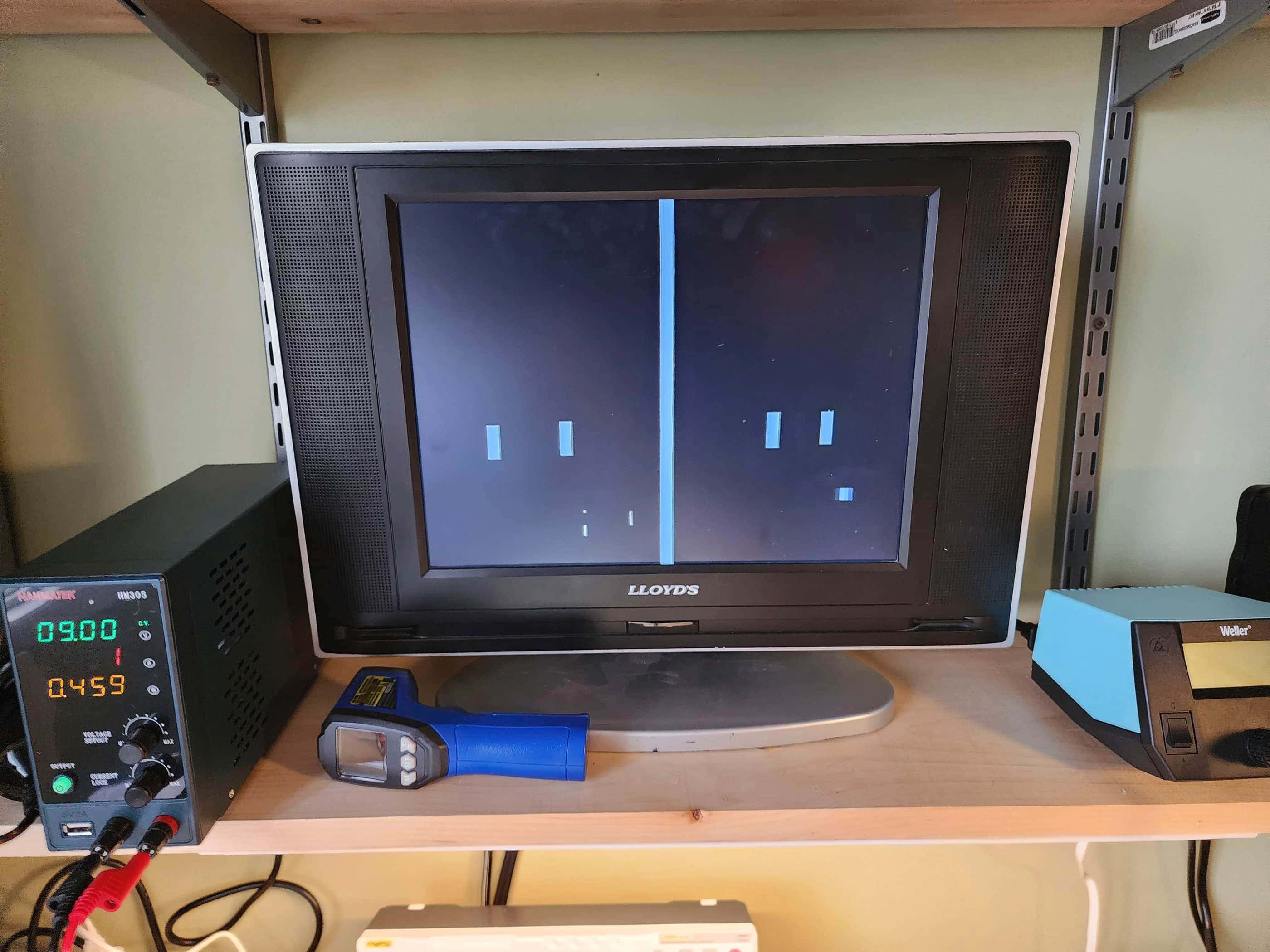
Once the composite output was in place, I then plugged in a spare 9V 1mA power adapter that I had on hand and turned the system on. Nothing… 🤔 I then turned on the sound switch and I heard some beeps which gave me hope. As there are a ton of potentiometers for adjusting the output of the system, I began looking at what my options were. I made a small adjustment to the vertical sync pot and all of a sudden I had video on my TV. It wasn’t great, but it was something.
I then played with both the horizontal and vertical pots until the output had stabilized a bit more; however, it was far from perfect. My scope showed that the output from pin 5 on IC5 was all over the place for frequency and by playing with the vertical and horizontal pots I could narrow this down. I also adjusted the right wall potentiometer and the goal location pot to make everything fit onto my TV (and make the ball reappear). Unfortunately, I could not get the flickering to completely settle down. Just when I thought it had stabilized, the entire output would begin to shake, go grey, and then cut out. Hmmmm…. 🤔
Thinking it might be a power issue, I desoldered and cleaned both the power switch and the game select switch. I also re-capped the board. This helped and I no longer had any vertical scrolling issues; however, the system would eventually destabilize after several minutes. This is when I discovered a blogpost on the Odyssey 100 by Nicole Express. This not only gave me a link to the original service manual but noted that the game logic can be messed up if the horizontal blanking is untuned. This is most evident when the auto serve doesn’t work after the right player is scored on – which was exactly what was happening to me. In fact, the system would be stable until the right player was scored on, thus making the entire display unstable.
A simple adjustment of the horizontal blanking to make the system detected the precise location where the ball leaves the right side of the screen made a huge difference. The auto serve now worked and the system no longer destabilized after the right player was scored on. This didn’t mean it was entirely perfect, but 90% of the time, everything functioned as it should. It also meant that I could use the frequency pots to dial in the output to 60Hz now that the logic wasn’t creating an issue.
One thing that I did notice however, was after powering the system on, it took several seconds for the display to stabilize. After it had ‘warmed-up’, it then functioned almost perfectly, so it may be that at some point, the ICs will have to be replaced. I also think the vertical and horizontal frequency pots will have to be tuned on a regular basis to keep the output on 60Hz. For now, however, I’d gotten the system back up and running. 🙂
I also made the decision to keep the composite mod in place due to the need for the proprietary switchbox if I didn’t replace the RF cable. Therefore, I added a minimalist 3.5mm TRRS jack onto the back that I paired to a 6” 3.5mm male to RCA female adapter. This kept the authenticity of the original RF display in place, but allowed it to function on a more modern TV. I prefer using TRRS jacks for composite mods because they generally blend in much better to the original aesthetics of the console.
Once all of this was finished, I then used some E6000 glue to repair the battery compartment though I could not get all the corrosion off the terminal. After a good clean and shine, I put the system back together and tested it out. Everything worked great minus the initial ‘warmup’. I’m very proud to have this unique piece of history as part of my collection! 😁
Parts & Products Used: 99% isopropyl alcohol; Chemical Guys Natural Shine; electrolytic capacitors (radial) – 50v 2.2μF (3); 25v 10 μF (2); 16v 470 μF (2); 16 v 220μF (1); 16v 47μF (1) 10v 22μF (2); dielectric grease.
style=”text-align: center;”>
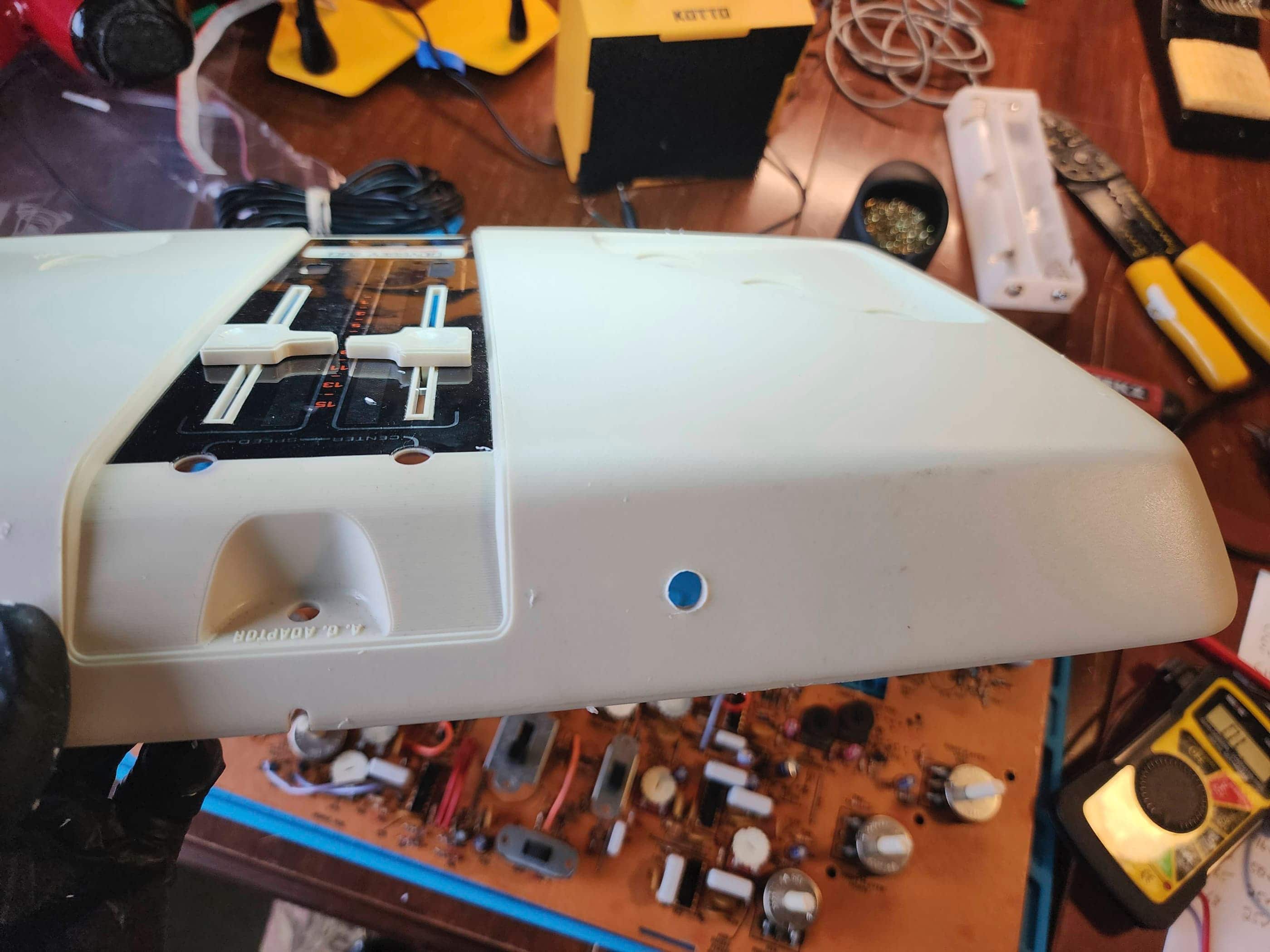
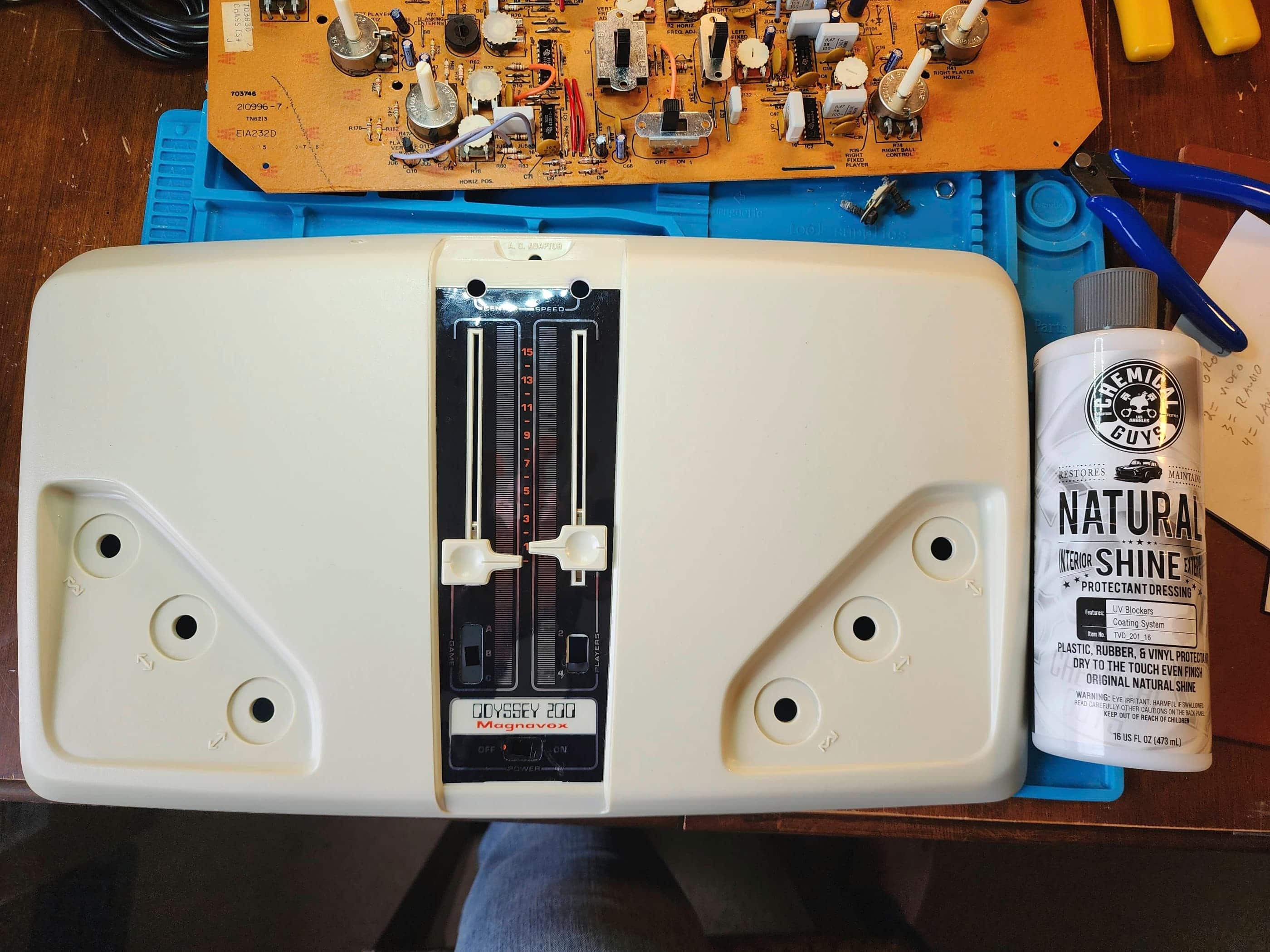
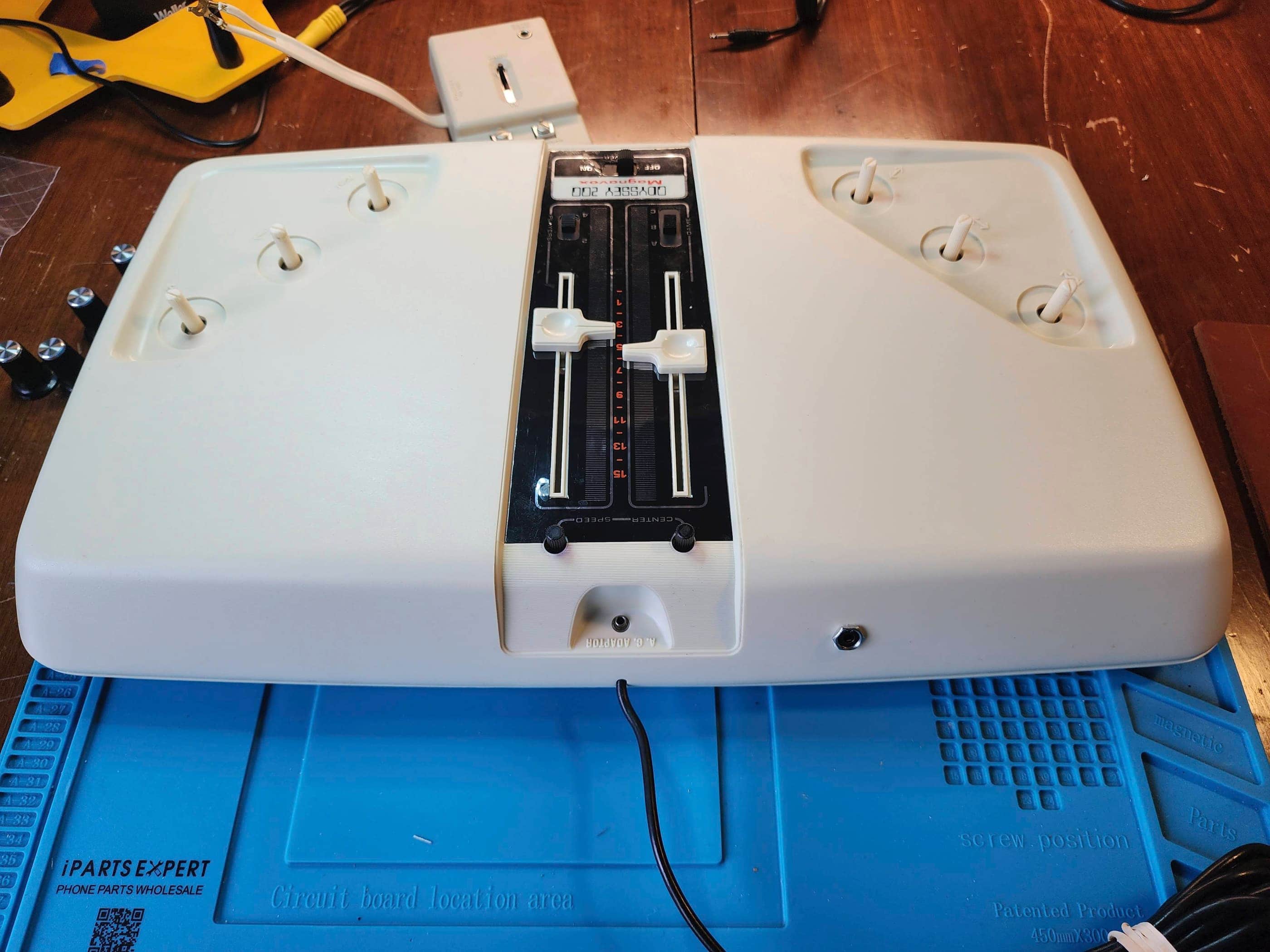
Magnavox Odyssey 200
Years (1975-1976)
Interesting Fact: The Odyssey 200 was released as the deluxe companion to the Odyssey 100. It featured the additional game of “Smash” (or handball / squash) and was the first video game console to allow for up to four paddles on screen. (source) It also featured a very rudimentary on-screen scoring system where two small and skinny rectangles (one for each player) would move to the right after a player scored. The winner / leader was the one whose rectangle was the furthest to the right. (source) At the time, it was more advanced than the Atari Pong console because of the options for three different games and for two or four paddles. (source)
Condition When Acquired: Fully Functional
Current Condition: Fully Functional


Project Details: Like the Odyssey 100, this unit came to me from the US, but this time it was Texas. I was excited because it arrived with days of the 100 which meant that I could work on both at more or less the same time.
Also like the 100, this 200 came with its original box, manuals, and TV switchbox. It also came with the original 9v 100 mA power adapter, that on initial testing, revealed it to only be outputting 7.3 to 7.8v. As this was no longer working, I relied on my benchtop supply for power.
Though the board is roughly the same as the 100, because there is a third game along with the option for four paddles on the screen at the same time, it has two more Texas Instrument chips and 15 electrolytic capacitors compared to 11 on the Odyssey 100. It also has an additional switch to toggle between two and four paddles and a larger game select switch. In fact, the two/four paddle switch is located where the power switch is on the Odyssey 100 and the power switch for the 200 is relocated to a horizontal position below the other two. There are also more adjustment pots to account for the four paddle options.
Despite these differences, the 200 allows for the same, easy composite mod as the 100. For the same reasons as I did on the 100 (the proprietary soldered RF jack along with a proprietary switchbox), I used this to test the system and as an eventual permanent modification. Tying the audio output into this setup also allows the shrill sound from the console to be left off in favour of a much more subdued sound through the TV.
Thankfully, unlike the Odyssey 100, this system worked pretty much flawlessly from the get-go. All I had to do was use the pots to adjust the right goalpost and the scoring location on the screen. I also adjusted the horizontal blanking to the proper location to ensure that the auto serve would work when the right player was scored on. This would also help prevent some of the logic stabilization issues that I encountered with the 100.
Since I had all the capacitors on hand, I re-capped the board, cleaned it up, and installed the composite mod. As I noted with 100 and with other systems, I prefer using 3.5mm TRRS jacks for composite mods because it means drilling only one hole and because of its size, it doesn’t wreck the original aesthetic of the console. Moreover, like the Odyssey 100, I left the original RF cable intact to maintain its authenticity. This unit now works just like it did in 1975. I just wish I could say the same!
Parts & Products Used: 99% isopropyl alcohol; Chemical Guys Natural Shine; electrolytic capacitors (radial) – 50v 2.2μF (6); 50v 4.7μF (1); 25v 10 μF (3); 16v 470 μF (1); 16 v 220μF (1); 16v 47μF (1) 10v 22μF (2)

Radio Shack TV Scoreboard
Years (1979 – 1983)
Interesting fact: This was my first-ever video game system! 🙂 One thing that makes it unique among Pong clones of the era, is that the console is handheld. (source)
Condition When Acquired: Fully Functional
Current Condition: Fully Functional


Project Details: I found this for $5 plus shipping on Ebay and the seller did not know if it worked, so I was thrilled when I hooked it up and everything including the very realistic light gun functioned perfectly. As I do with all my systems, I pulled it apart and gave it a thorough cleaning while looking for any current or potential issues. I didn’t find any and gave it a clean bill of health. I’ve paired this system with my 1978 Zenith Chromacolor II TV and I can now relieve Christmas 1979 anytime I want – minus the huge fight I had with my dad about how to hook it up. 😂
Parts & Products Used: 99% isopropyl alcohol; Chemical Guys Natural Shine

Ridgewood Gamatic 7600
Years (1976 – 197?)
Interesting fact: This system was sold under different brand names worldwide and was originally made in Korea. (source)
Condition When Acquired: Non-Functional (DOA)
Current Condition: Fully Functional


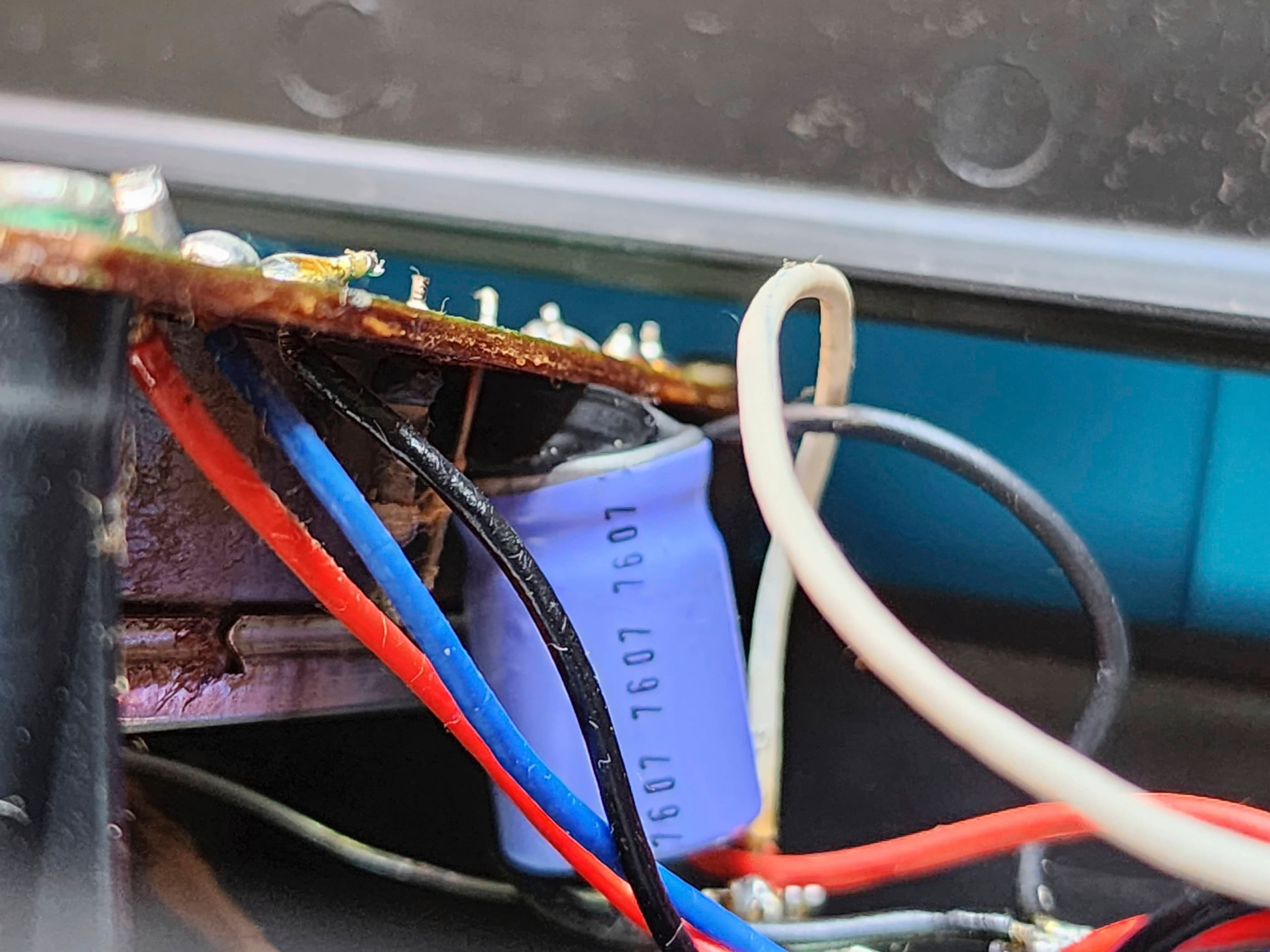


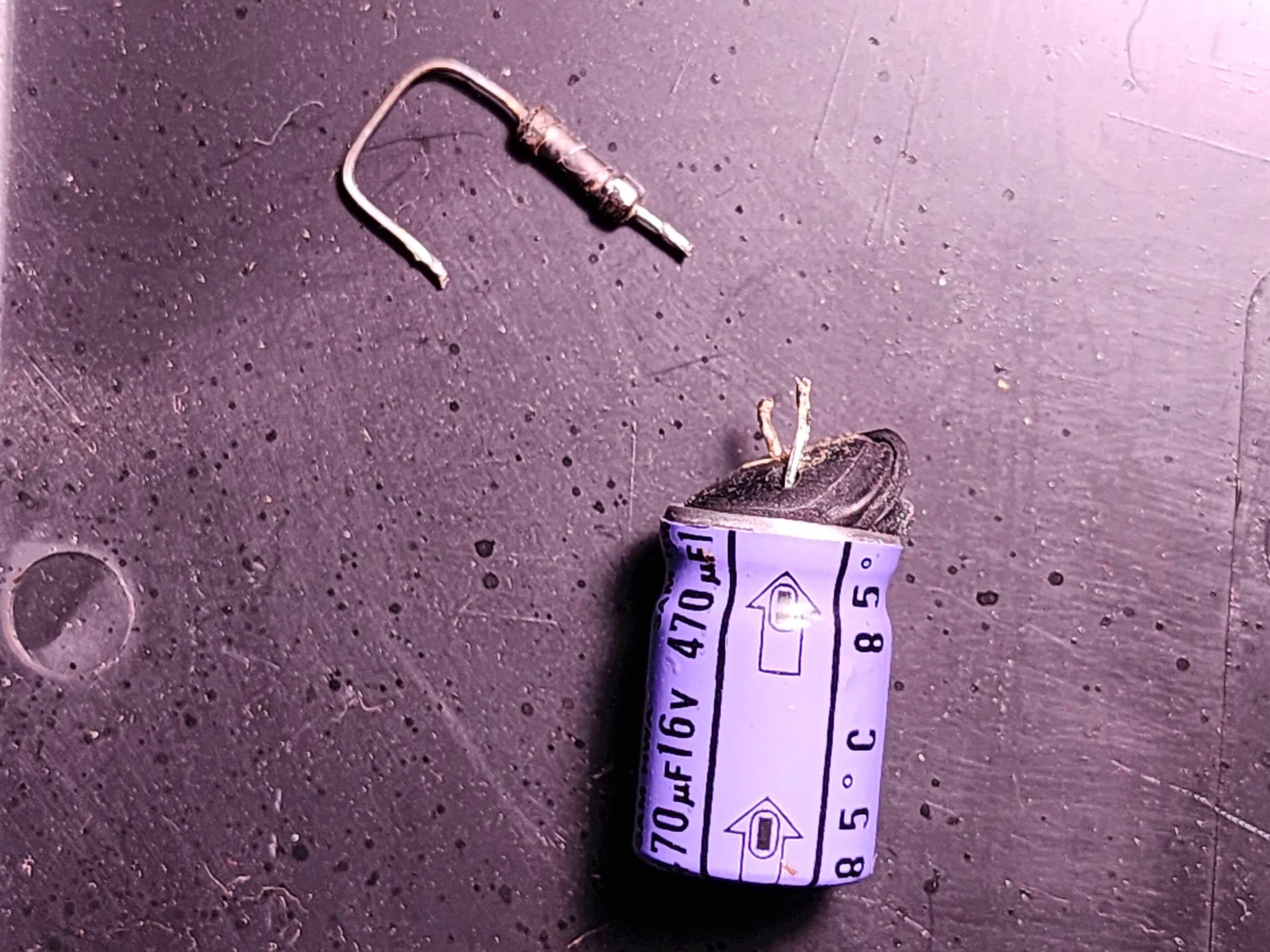
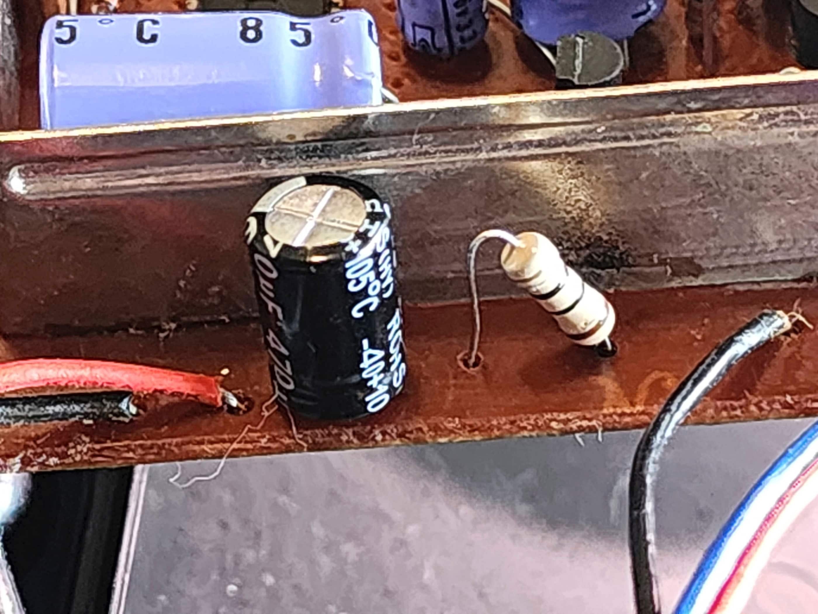

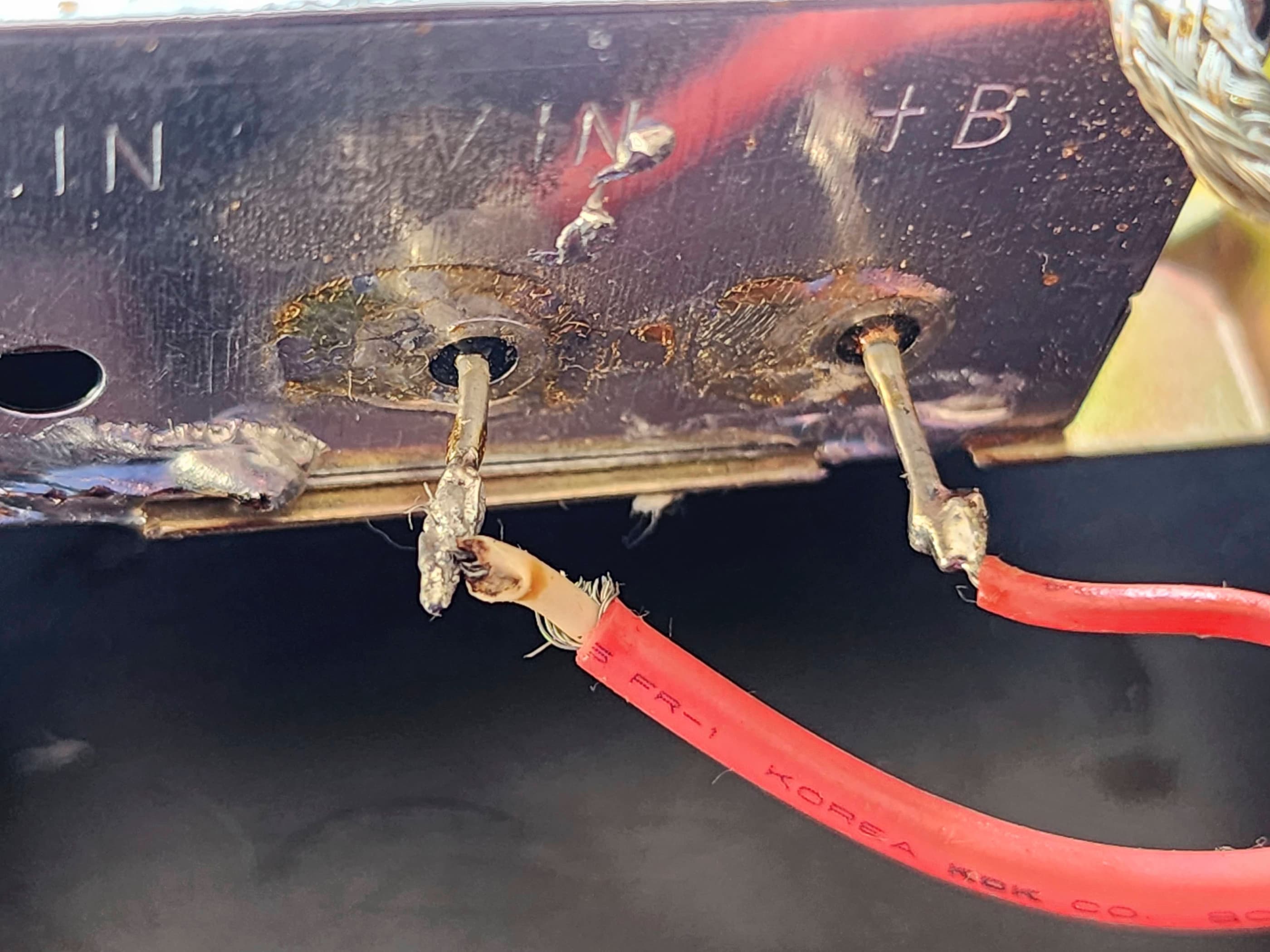


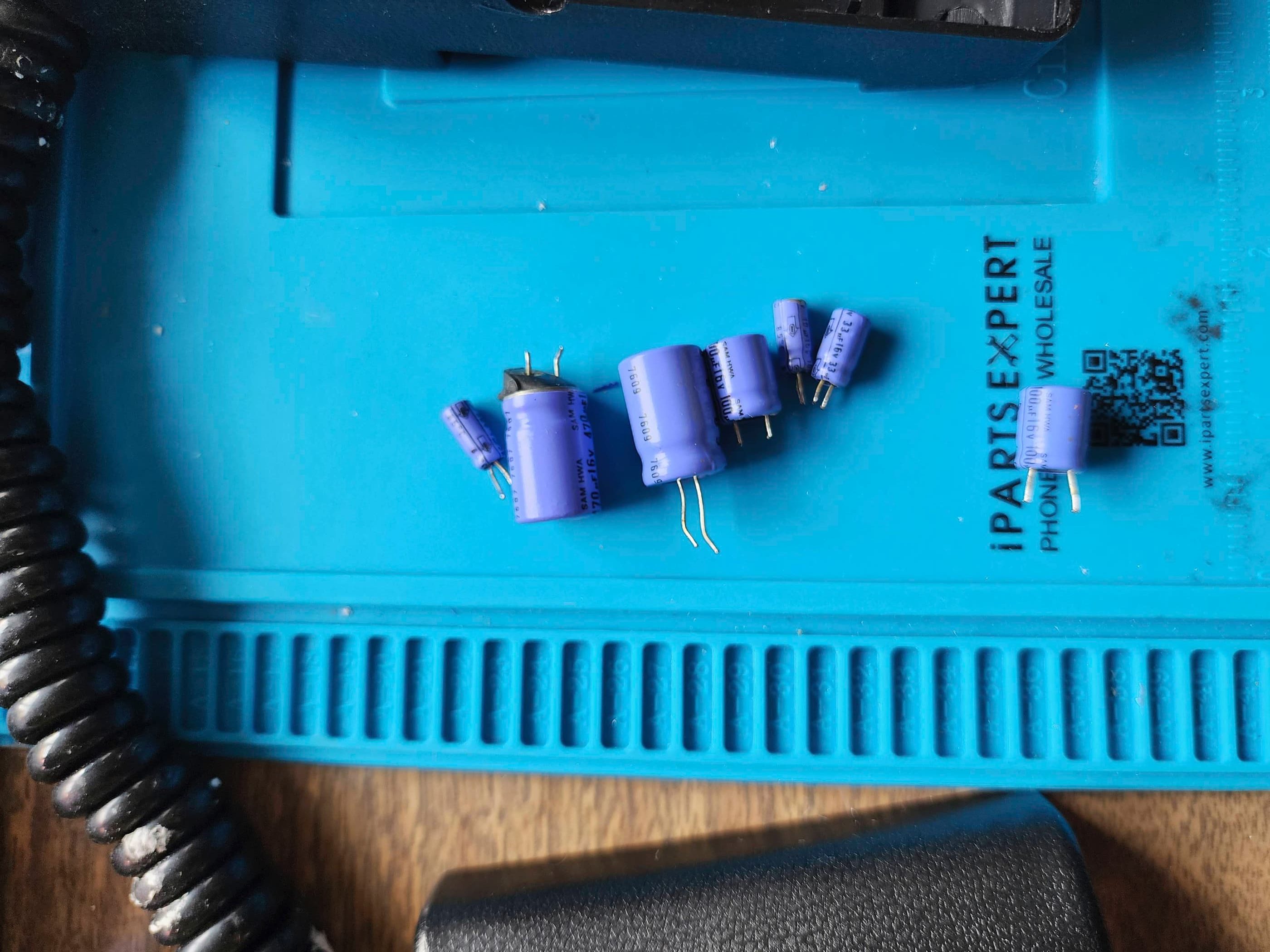

Project Details: This system came to me in its original box complete with the styrofoam and plastic wrap. On first inspection, it looked almost new. Unfortunately, it was DOA and as soon as I opened it up, I could see why. There was a blown 16v 470μF capacitor where the power connects to the board. To make matters worse, the subsequent resistor was also fried beyond recognition. As I couldn’t find a schematic online, finding the right replacement would be tricky. My guess is that someone plugged in a power adapter with the wrong polarity and/or voltage at some point in the console’s life and the capacitor and resistor sacrificed themselves (which is what they were supposed to do) to save the rest of the board. To fix it, I replaced the faulty capacitor and then while trying to do the math, stumbled on an Atari Age forum where someone in Europe had a similar problem. The conclusion was that it was originally 10 Ω +-5 resistor and the math seemed to concur – so I thought, let’s try it – and when I powered the unit own using batteries, it sprung to life! I then re-capped the entire board and pulled apart the potentiometers in the paddles to clean them. I also found a substitute power adapter with the proper polarity and voltage that I could pair with the system. This system now has new life and works flawlessly.
Parts & Products Used: 99% isopropyl alcohol; Chemical Guys Natural Shine; electrolytic capacitors (radial) – 16v 470μF (2), 16v 100μF (2), 16v 33μF (1), 16v 10μF (1), 50v 1μF (1); resistors – 10 Ω +-5% (1)


You must be logged in to post a comment.